
Фотографии

-

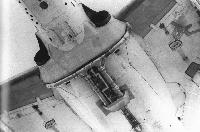
Регистрационный номер: N9417H One of the variable stability B-26s as it appeared in later life in Calspan markings. This particular aircraft crashed at Edwards Air Force Base in the early 1980s.
Самолёты на фотографии: Douglas A-26 / B-26 Invader - США - 1942
-

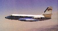
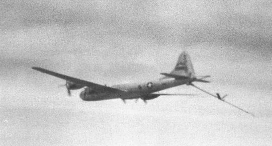
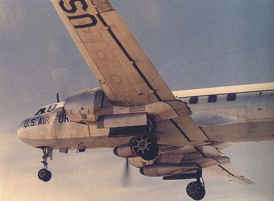
This KB-29 was equipped with in icing system mounted on its refueling boom.
Самолёты на фотографии: Boeing B-29 Superfortress - США - 1942
-

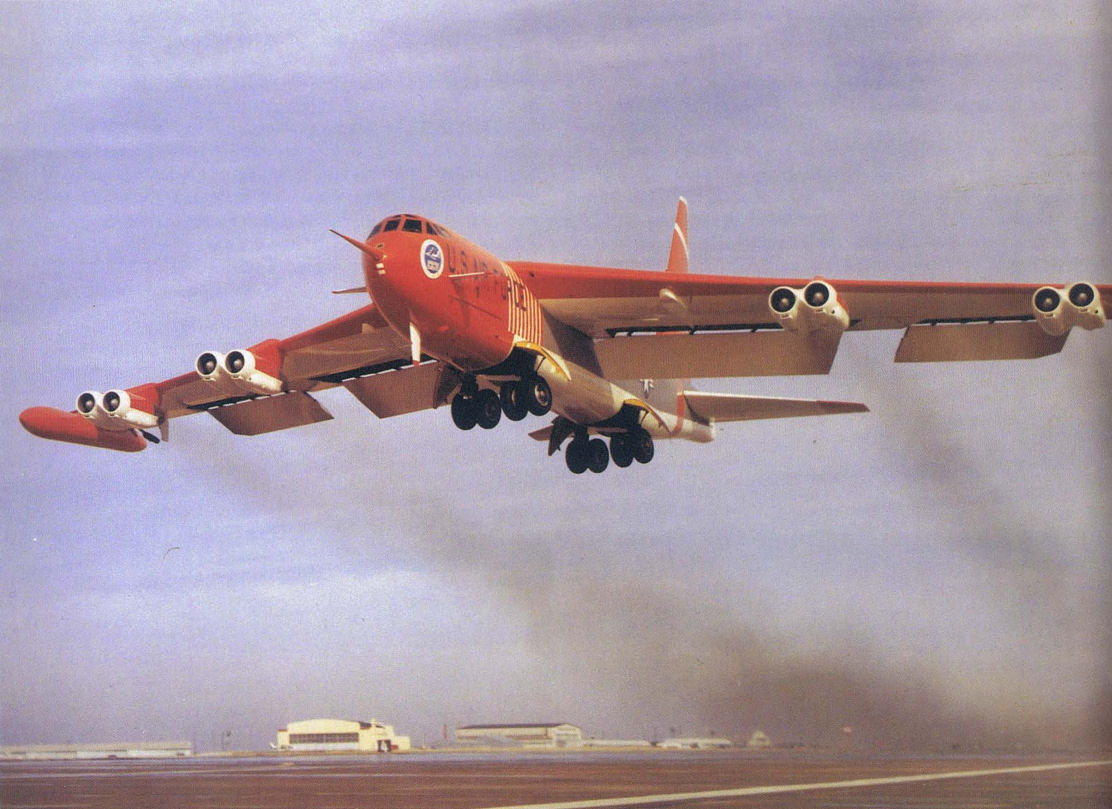
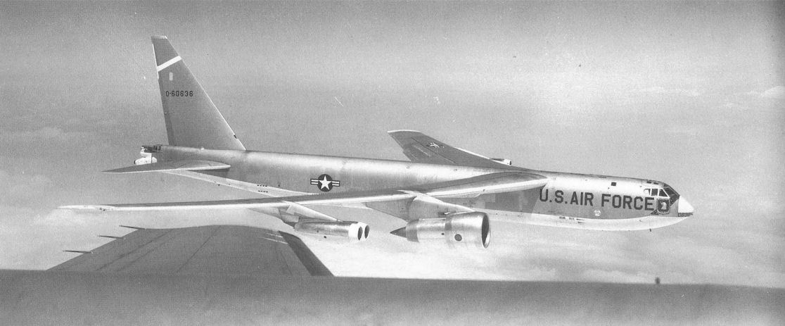
The testbed B-52 is shown here in its CCV configuration. It was characterized by its large forward probe and two sets of fuselage-mounted canards. Note the high-visibility paint scheme.
Самолёты на фотографии: Boeing B-52 Stratofortress - США - 1955
-

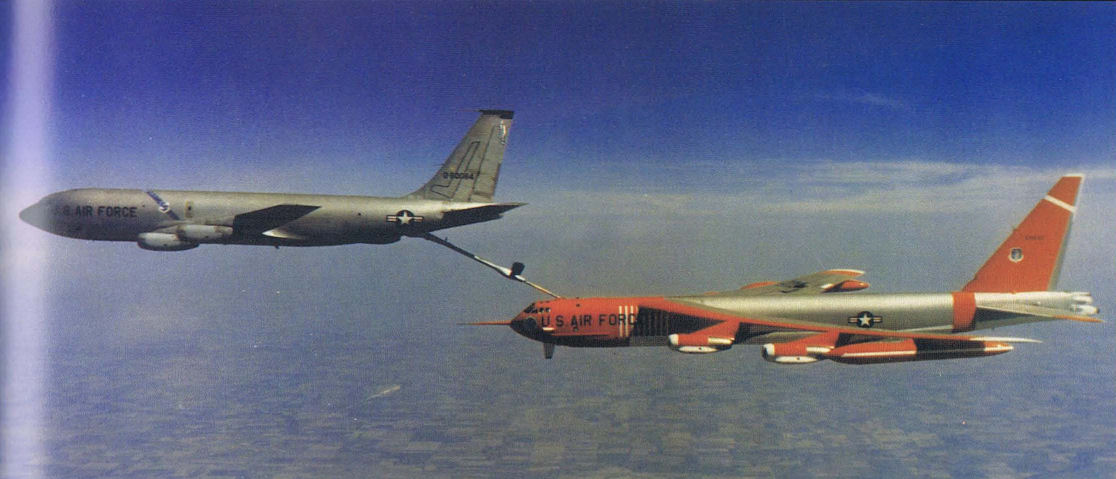
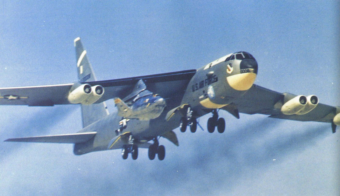
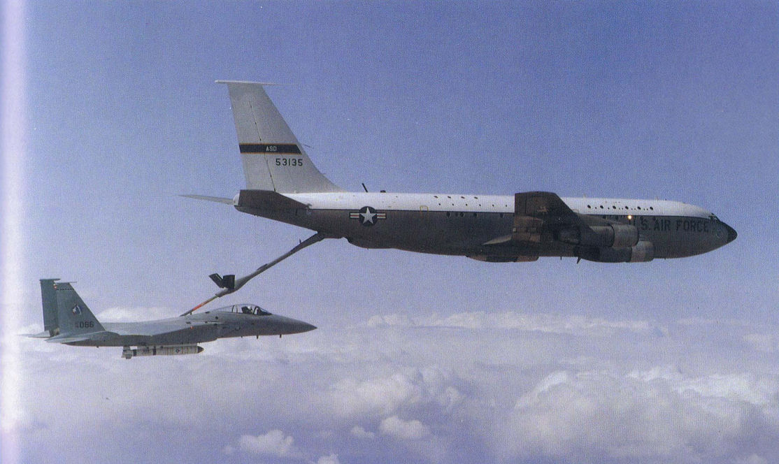
The CCV NB-52E refueling from a KC-135 tanker. Fly-by-wire controls made the aircraft more stable in turbulence, making in-flight refueling much easier.
Самолёты на фотографии: Boeing B-52 Stratofortress - США - 1955Boeing KC-135 Stratotanker / C-135 Stratolifter - США - 1956
-

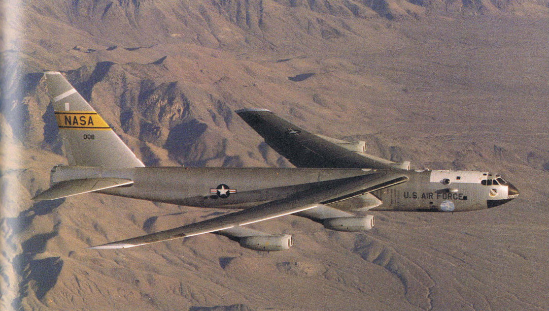
The special right side pylon located between the fuselage and inboard engine was the mounting location for the many test vehicles carried by the NB-52 (008).
Самолёты на фотографии: Boeing B-52 Stratofortress - США - 1955
-

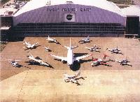
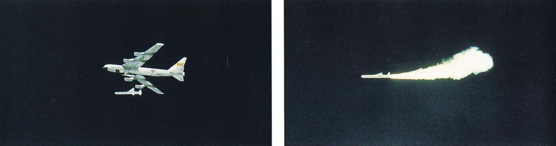
The commercially-developed Pegasus space launch vehicle races away from its NASA NB-52 launch aircraft.
Самолёты на фотографии: Boeing B-52 Stratofortress - США - 1955
-

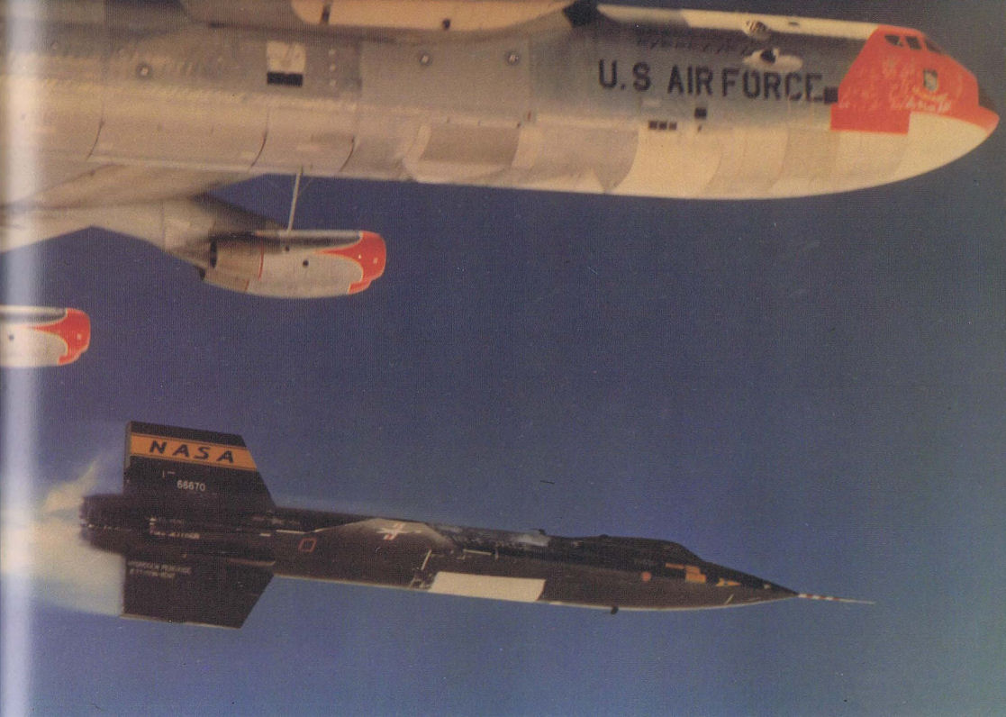
The NASA NB-52 served as the launching aircraft for many space and aeronautical vehicles. Here, it is seen launching the X-15, certainly one of the most-often seen photos of this aircraft.
Самолёты на фотографии: Boeing B-52 Stratofortress - США - 1955North American X-15 - США - 1959
-

The X-24 lifting body was one of many vehicles carried aloft by the NB-52 (0008) launching aircraft.
Самолёты на фотографии: Boeing B-52 Stratofortress - США - 1955Martin X-24A - США - 1969
-

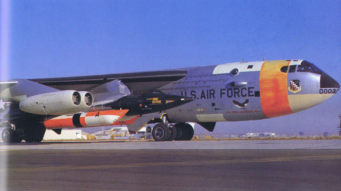
The NB-52 (0003) carrier aircraft is shown carrying an early M2-F2 lifting body test vehicle. This NB-52 is currently on display at Pima County Air Museum, Tucson, Arizona.
Самолёты на фотографии: Boeing B-52 Stratofortress - США - 1955NASA/Northrop M2-F2 - США - 1966
-

This vintage B-52 was modified into a testbed configuration to test the huge TF-39 powerplant for the C-5A Galaxy. The engine was carried on the right inboard pylon.
Самолёты на фотографии: Boeing B-52 Stratofortress - США - 1955
-

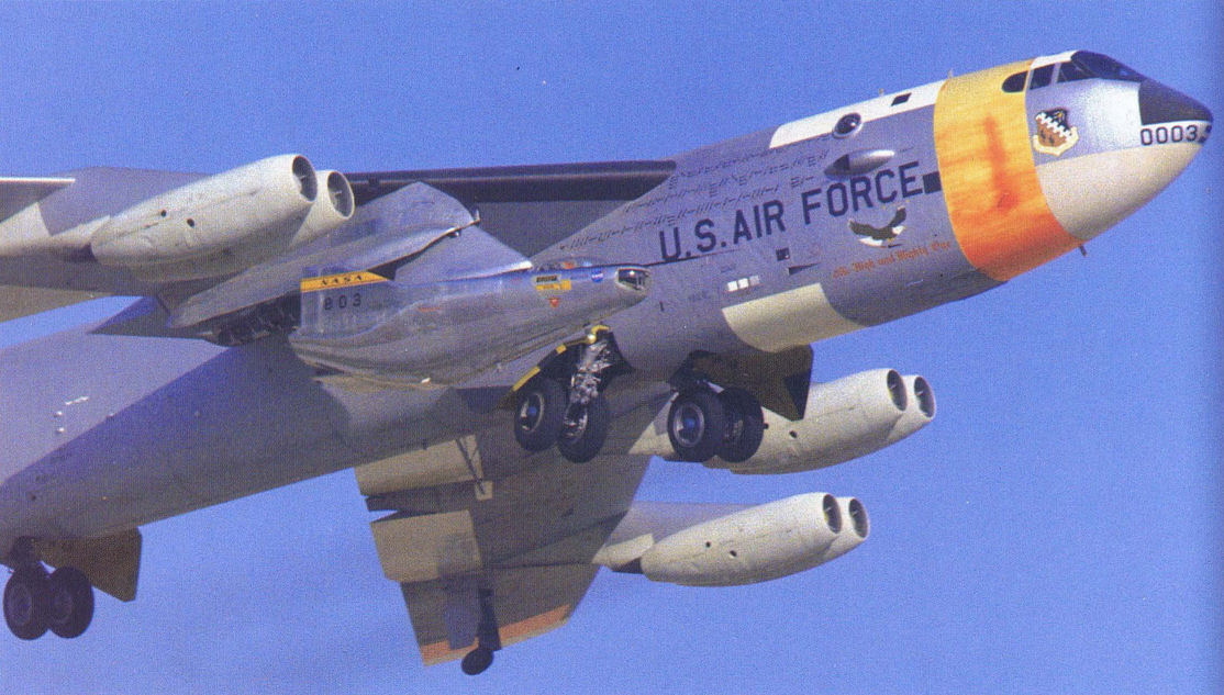
This particular carrier B-52 (003) was the first of the two testbeds, but was retired in 1969 leaving only one to carry on. Here is shown carrying a later version of the X-15.
Самолёты на фотографии: Boeing B-52 Stratofortress - США - 1955North American X-15 - США - 1959
-

The CCV B-52 sits ingloriously at Davis-Montham AFB, awaiting possible future work in 1988.
Самолёты на фотографии: Boeing B-52 Stratofortress - США - 1955
-

An almost identical B-52 testbed aircraft was configured to test the engine for the Boeing 747. The JT9D engine was carried in the same inboard rightside position.
Самолёты на фотографии: Boeing B-52 Stratofortress - США - 1955
-

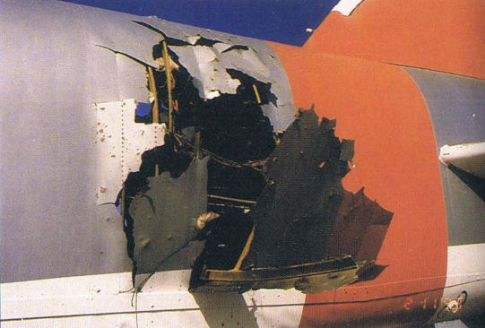
The results of 1994 vulnerability testing to study how an internal explosion damages the structure of a large aircraft.
Самолёты на фотографии: Boeing B-52 Stratofortress - США - 1955
-
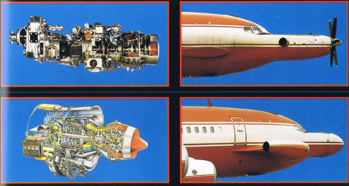
This Boeing 720 transport is used by Pratt & Whitney Canada to carry a number of different propulsion systems.
Самолёты на фотографии: Boeing Boeing 707/720 - США - 1954
-

Either a turboprop or pure jet engine can be mounted on the forward fuselage of this testbed transport.
Самолёты на фотографии: Boeing Boeing 707/720 - США - 1954
-

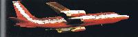
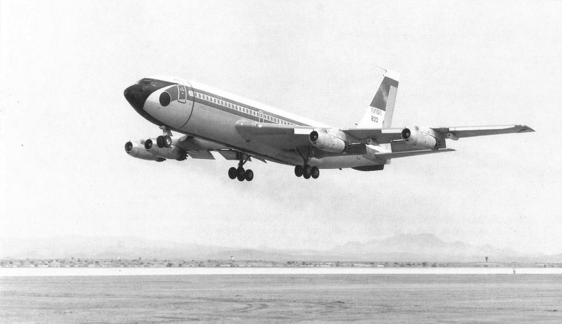
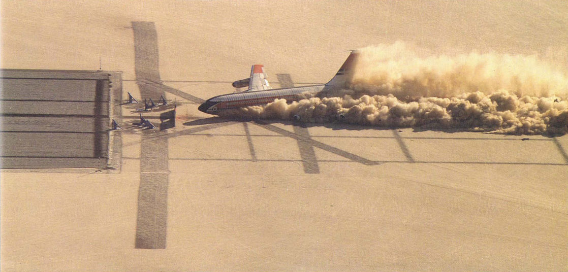
NASA/Boeing 720 taking off on a test flight prior to the actual crash test.
Самолёты на фотографии: Boeing Boeing 707/720 - США - 1954
-
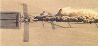
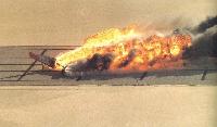
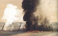
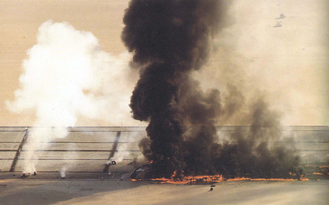
The Boeing 720 CID testbed aircraft erupts in flames as it slides through the impact site at Edwards Air Force Base, California, the ultimate price a testbed occasionally has to pay. The sequence shows the airplane hitting left wing low, impacting the barriers and tearing off the right wing. It then erupted into a fireball, but the flames from the special fuel quickly died out on their own.
Самолёты на фотографии: Boeing Boeing 707/720 - США - 1954
-
Самолёты на фотографии: Boeing Boeing 707/720 - США - 1954
-
Самолёты на фотографии: Boeing Boeing 707/720 - США - 1954
-

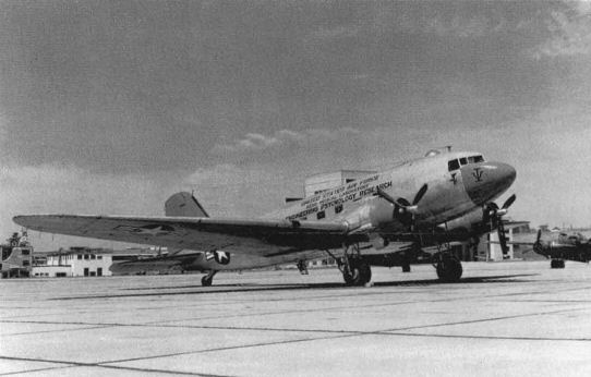
The use of production aircraft for simulation and testbed missions has been carried out for many years. Here, a C-47 assigned to the Air Force Medical Research Laboratory was used in the 1950s for human engineering experiments.
Самолёты на фотографии: Douglas DC-3 / C-47 Skytrain/С-53 Skytrooper / Dakota - США - 1935
-

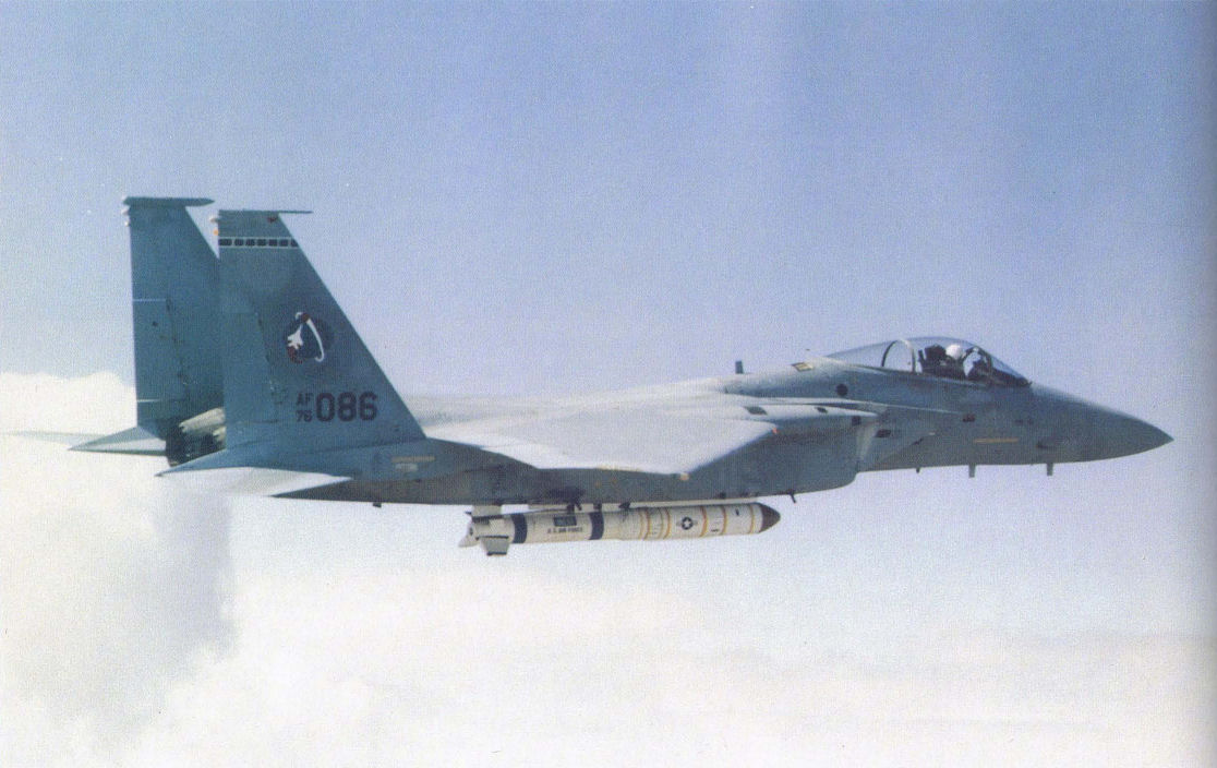
The F-15A ASAT testbed aircraft is seen being mid-air refueled by a KC-135 tanker. The ASAT weapon can be seen mounted beneath the aircrafts fuselage.
Самолёты на фотографии: Boeing KC-135 Stratotanker / C-135 Stratolifter - США - 1956McDonnell Douglas F-15A/C Eagle - США - 1972
-

The HIDEC F-15 test aircraft was used to carry out flight research on integrated digital electronic flight control systems.
Самолёты на фотографии: McDonnell Douglas F-15A/C Eagle - США - 1972
-

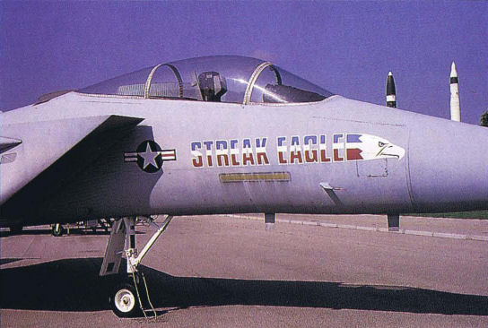
This particular F-15 testbed was easily recognizable from the flashy logo it carried on both sides of its nose.
Самолёты на фотографии: McDonnell Douglas F-15A/C Eagle - США - 1972
-

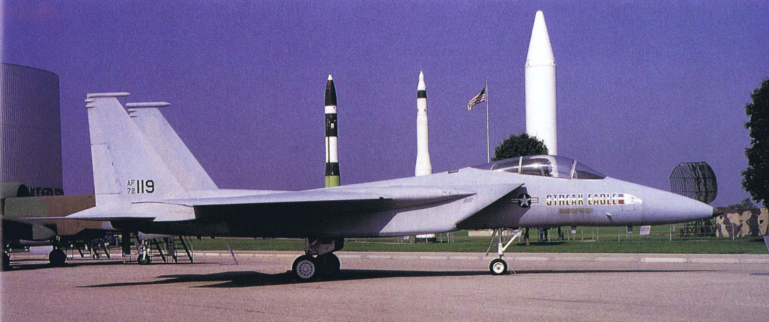
The F-15 Streak Eagle was a different type of testbed, because it was specifically designed to capture time-to-climb world records, which it did.
Самолёты на фотографии: McDonnell Douglas F-15A/C Eagle - США - 1972
-

This is definitely a unique space missile launching platform. The concept proved successful knocking down a U.S. satellite, but the system would never be fielded operationally.
Самолёты на фотографии: McDonnell Douglas F-15A/C Eagle - США - 1972
-

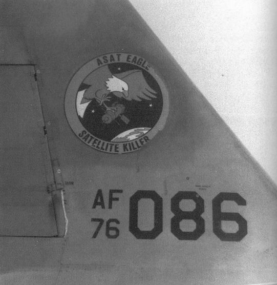
The F-15 ASAT Program was identified on the F-15A testbed aircraft by this characteristic logo on the tail.
Самолёты на фотографии: McDonnell Douglas F-15A/C Eagle - США - 1972
-

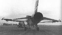
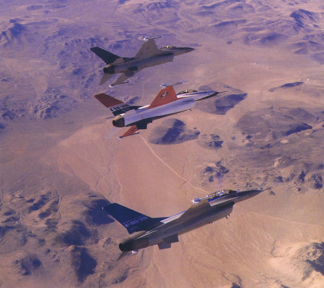
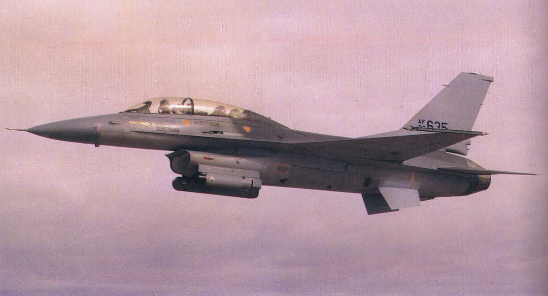
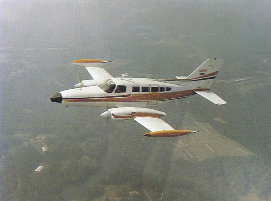
In a similar experiment to the F-16/79, an F-16 was also modified to carry the F101 powerplant. Again, the concept would not be adopted for the F16/101. The brightly-colored aircraft prototype is the middle aircraft in this formation.
Самолёты на фотографии: General Dynamics F-16A/C/E Fighting Falcon - США - 1974General Dynamics F-16B/D Fighting Falcon - США - 1977
-

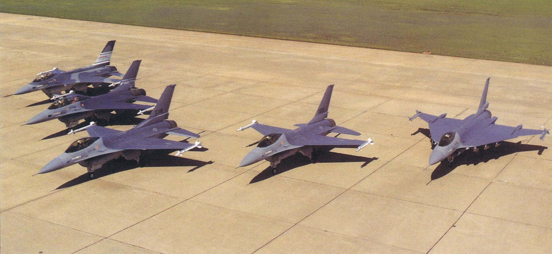
The F-16XL is shown on the far right, sitting among a number of different F-16 variant aircraft.
Самолёты на фотографии: General Dynamics F-16A/C/E Fighting Falcon - США - 1974General Dynamics F-16XL - США - 1982
-

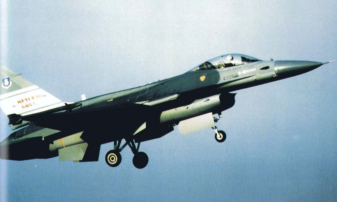
The AFTI/F-16 was also modified into a Close Air Support (CAS) configuration.
Самолёты на фотографии: General Dynamics F-16A/C/E Fighting Falcon - США - 1974
-

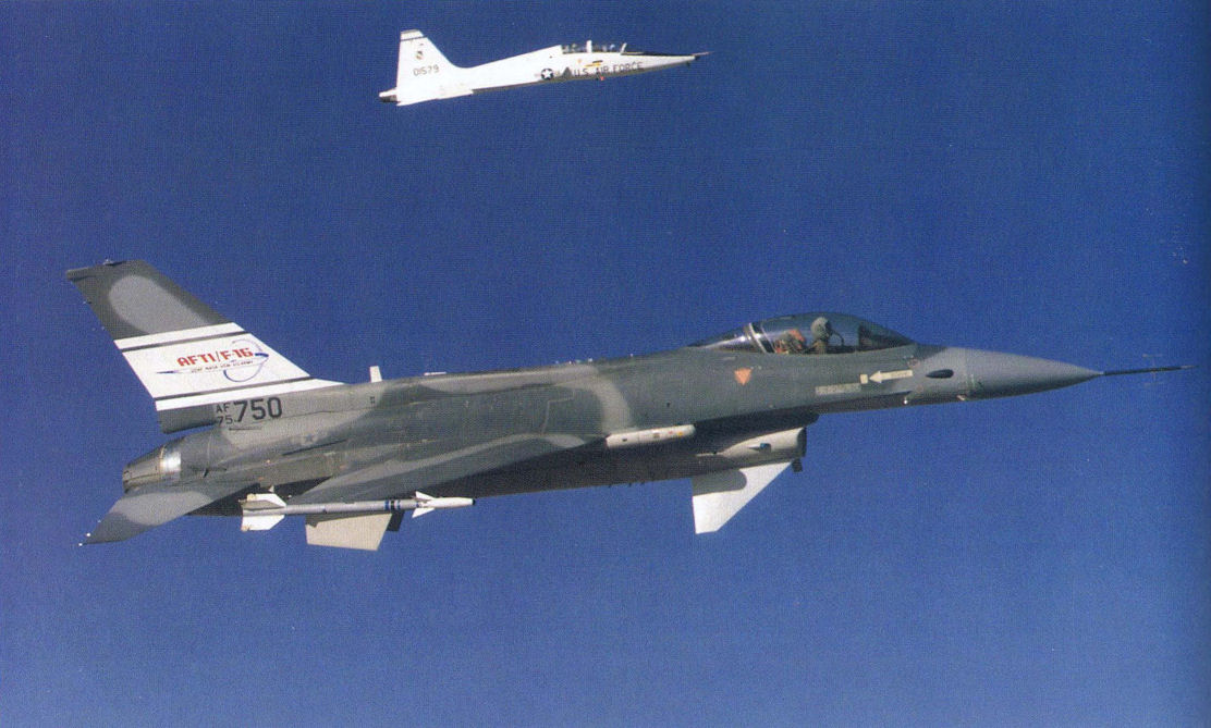
The AFTI/F-16 in formation with a T-38 chase aircraft.
Самолёты на фотографии: General Dynamics F-16A/C/E Fighting Falcon - США - 1974Northrop T-38 Talon - США - 1959
-

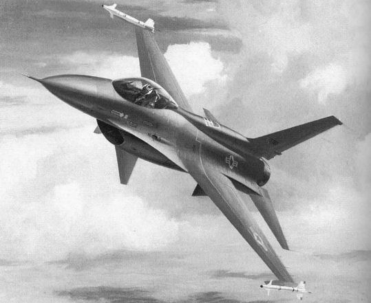
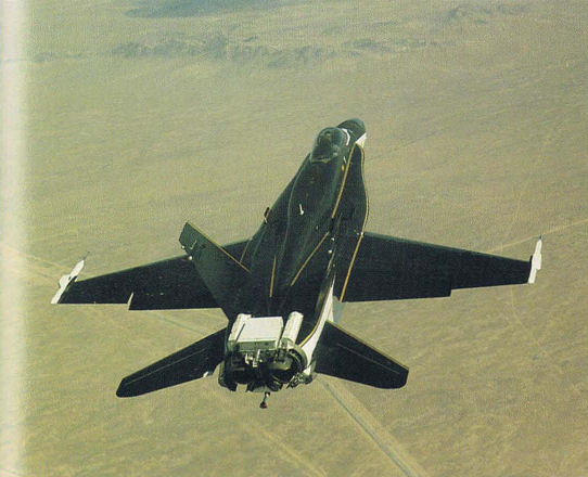
The mounting location for the engine-mounted canards is shown here. The program demonstrated advanced maneuver capabilities applicable to future fighters.
Самолёты на фотографии: General Dynamics F-16A/C/E Fighting Falcon - США - 1974
-

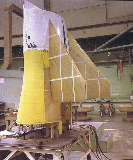
The forward canards for the CCV testbed are shown during the fabrication process.
Самолёты на фотографии: General Dynamics F-16A/C/E Fighting Falcon - США - 1974
-

The AFTI/F-16 is one of the most capable research aircraft ever constructed. Begun in the early 1980s time period, the program was still active in the mid-1990s.
Самолёты на фотографии: General Dynamics F-16A/C/E Fighting Falcon - США - 1974
-

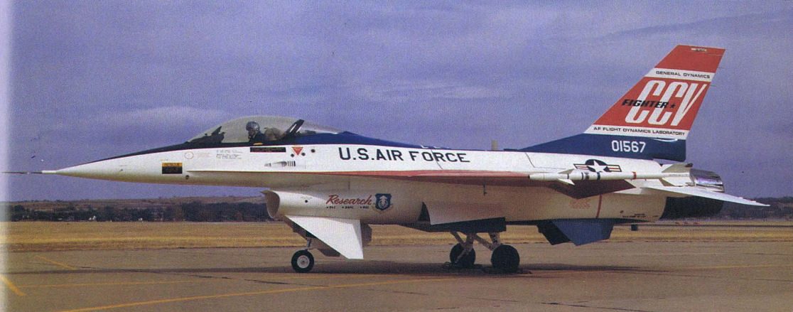
The F-16 prototype was the testbed aircraft for the CCV program, and later the FLOTRAK investigations.
Самолёты на фотографии: General Dynamics F-16A/C/E Fighting Falcon - США - 1974
-
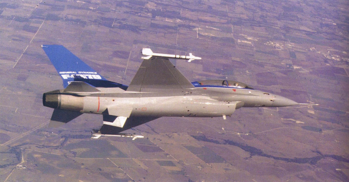
Here, the F-16 CCV testbed is employed in its second test program, the FLOTRAK program. The program attempted to develop a system to keep heavily-loaded fighters from sinking into the mud.
Самолёты на фотографии: General Dynamics F-16A/C/E Fighting Falcon - США - 1974
-
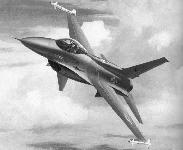
This 1980 artist's concept shows the design of the AFTI/F-16 configuration which would follow in two years. The concept incorporated fly-by-wire controls, advanced displays, integrated flight control system, and weapons fire controls.
Самолёты на фотографии: General Dynamics F-16A/C/E Fighting Falcon - США - 1974
-

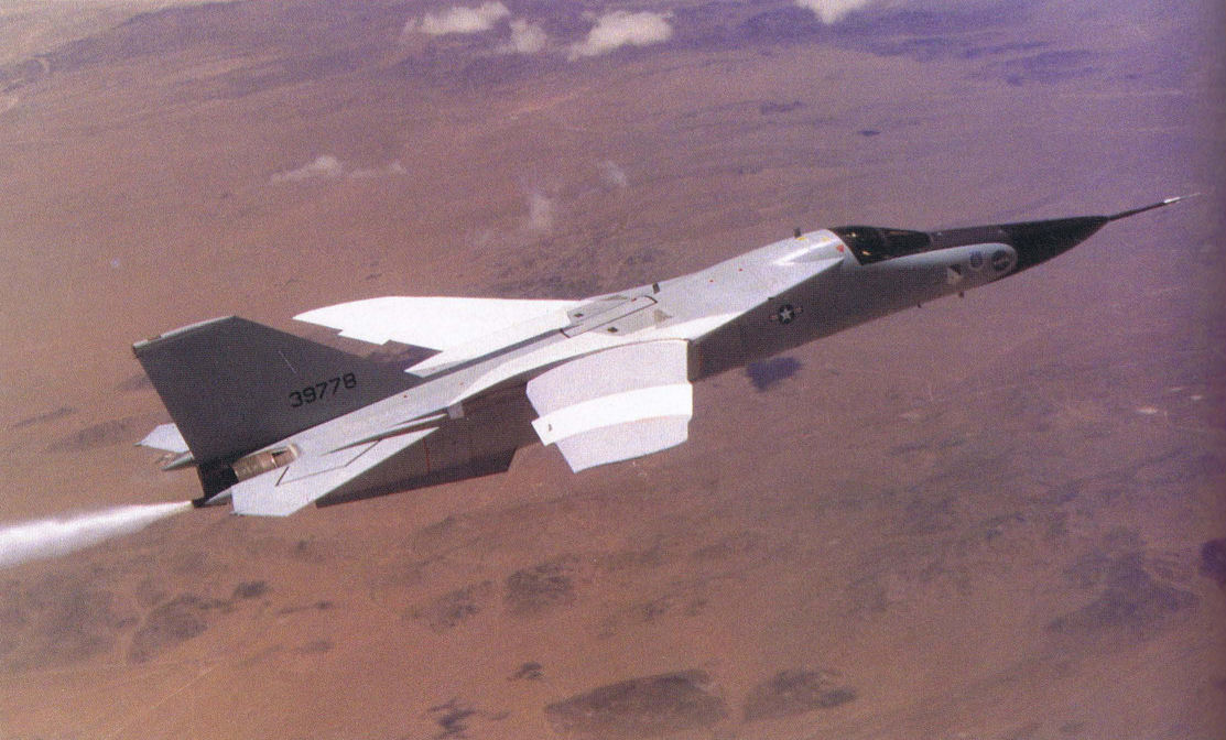
Designed as a possible third-country fighter, this modified F-16 (known as the F-16/79) carried the J-79 powerplant.
Самолёты на фотографии: General Dynamics F-16B/D Fighting Falcon - США - 1977
-

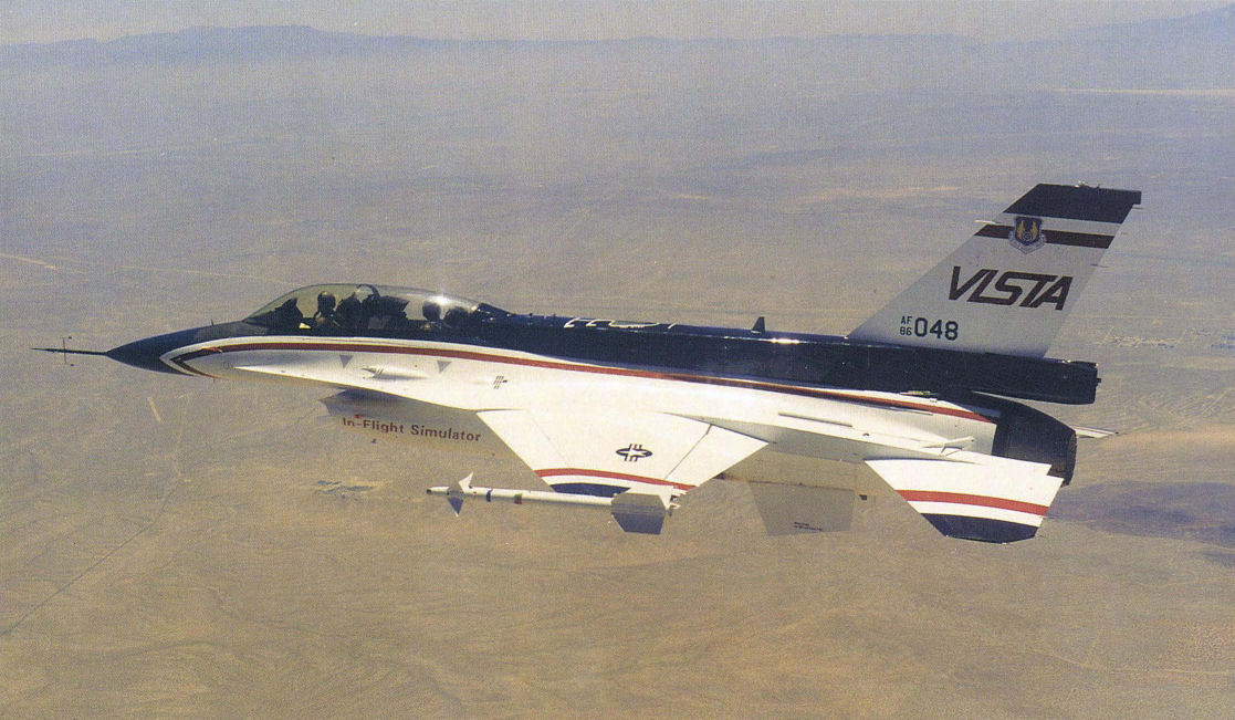
One of the most complicated modifications ever made to a simulator aircraft was the VISTA modification made to this F-16.
Самолёты на фотографии: General Dynamics F-16B/D Fighting Falcon - США - 1977
-

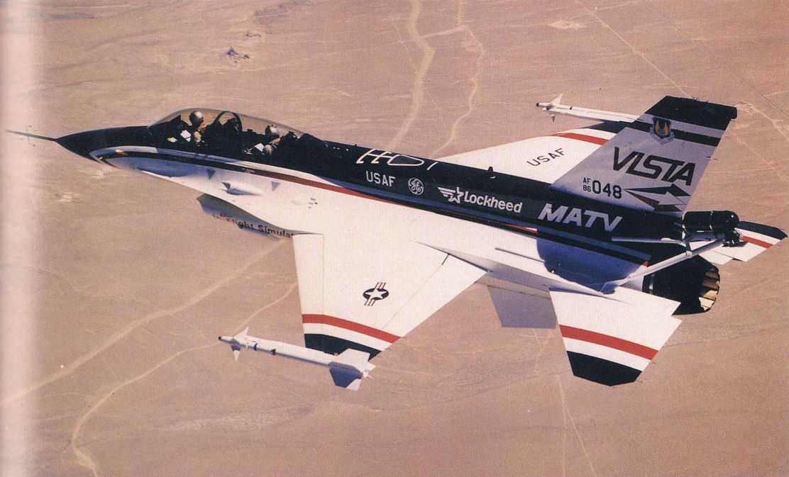
Prior to its completion as in-flight simulator, the same aircraft was modified with additional maneuver capabilities in this striking MATV configuration.
Самолёты на фотографии: General Dynamics F-16B/D Fighting Falcon - США - 1977
-

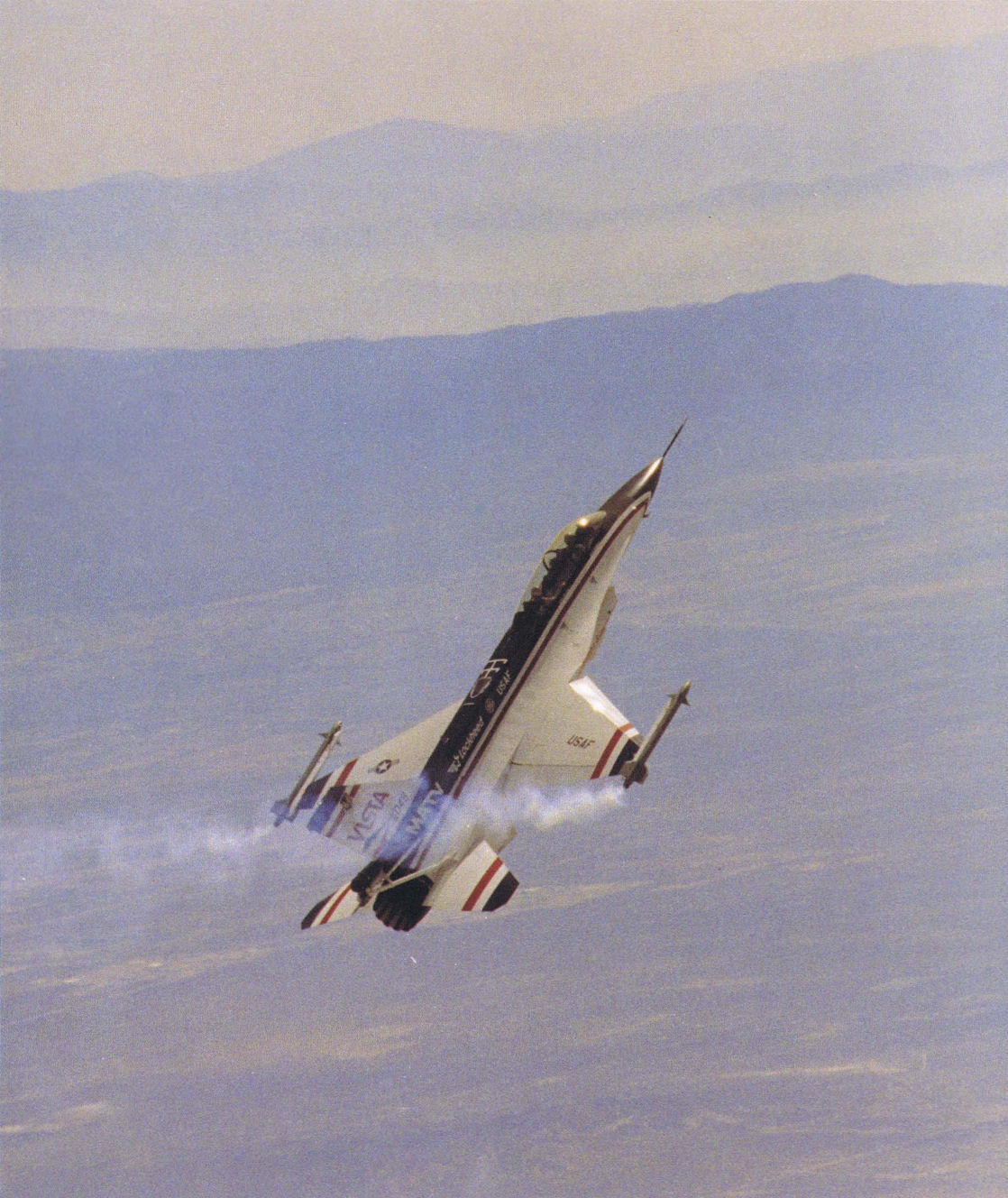
With smoke pouring from its smoke generators, the VISTA/MATV aircraft demonstrates its high angle-of-attack capability. With the nozzle deflecting the thrust upward, the high angle of attack ability can be accomplished.
Самолёты на фотографии: General Dynamics F-16B/D Fighting Falcon - США - 1977
-

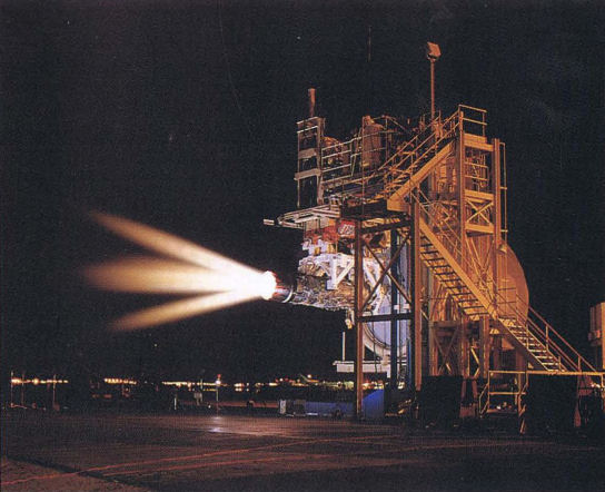
The MATV engine is shown in a test stand demonstrating the extent to which the exhaust can be deflected.
Самолёты на фотографии: General Dynamics F-16B/D Fighting Falcon - США - 1977
-

F-16 testbed aircraft fitted with a LANTIRN navigation pod during early testing of the system.
Самолёты на фотографии: General Dynamics F-16B/D Fighting Falcon - США - 1977
-

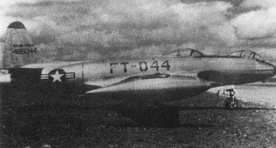
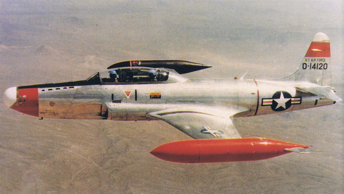
Регистрационный номер: FT-044 Would you believe this F-80 testbed? This unique testbed investigated the concept of a prone-lying pilot, hence the forward-located second canopy.
Самолёты на фотографии: Lockheed P-80 Shooting Star - США - 1944
-

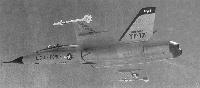
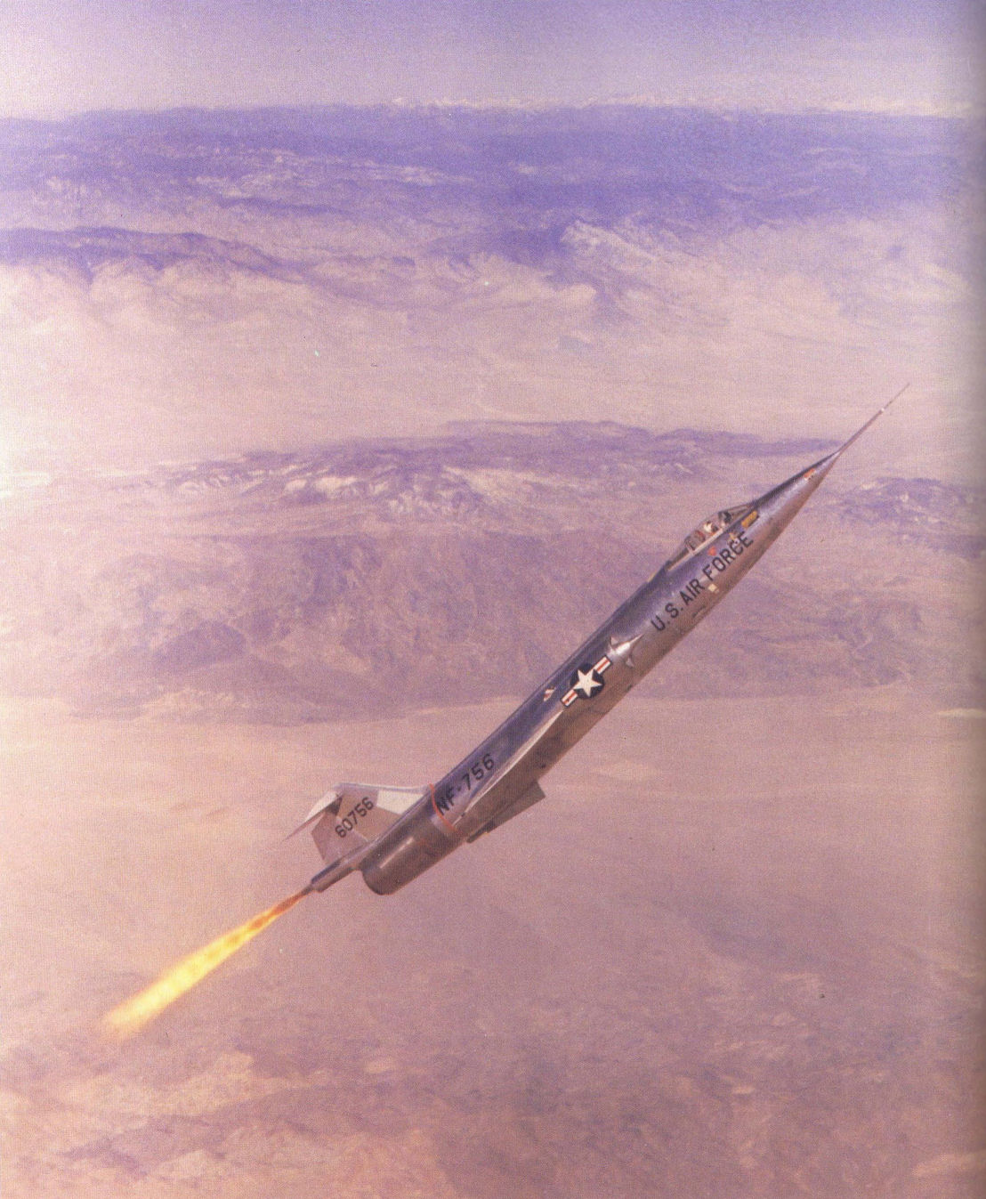
Регистрационный номер: NF-756 The NF-104 is shown in a zoom climb with the aid of its rocket engine.
Самолёты на фотографии: Lockheed F-104G Starfighter - США - 1959
-

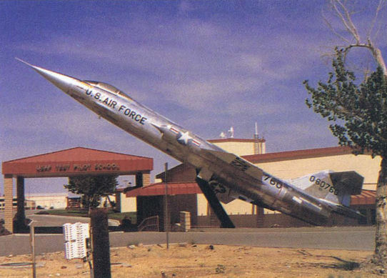
Регистрационный номер: NF-760 The NF-104 research aircraft is now on display at the Air Force Test Pilot School at Edwards Air Force Base.
Самолёты на фотографии: Lockheed F-104G Starfighter - США - 1959
-

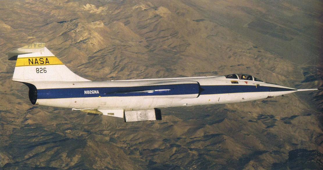
Регистрационный номер: N826A [2] Now retired, the Number 826 F-104 was used to test thermal insulation tiles during its final missions.
Самолёты на фотографии: Lockheed F-104G Starfighter - США - 1959
-

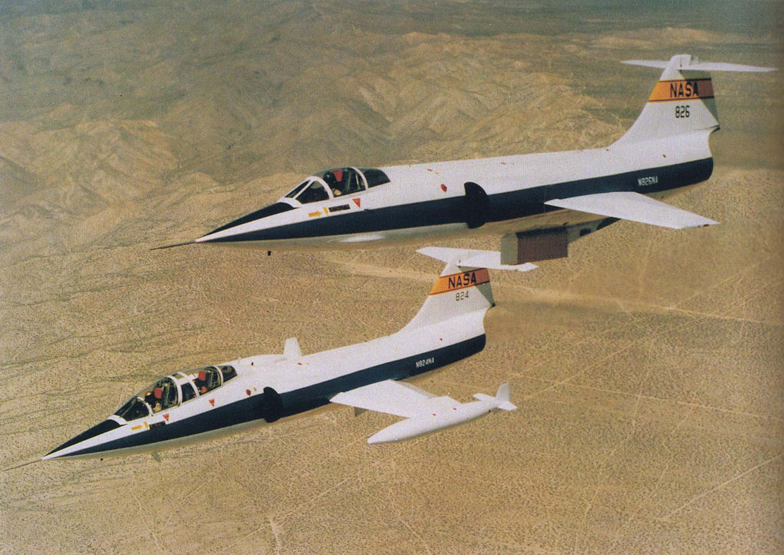
Регистрационный номер: N824NA, N826A [2] This pair of NASA F-104 testbed aircraft long performed low L/D flight testing.
Самолёты на фотографии: Lockheed F-104B / F-104D/ TF-104G - США - 1957Lockheed F-104G Starfighter - США - 1959
-

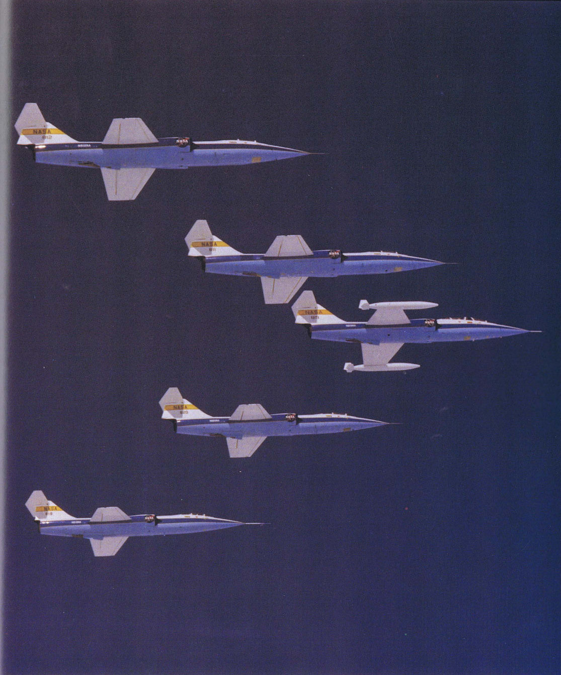
You better believe that NASA loved the F-104 as a testbed aircraft. Here the fleet is aloft in formation.
Самолёты на фотографии: Lockheed F-104G Starfighter - США - 1959
-

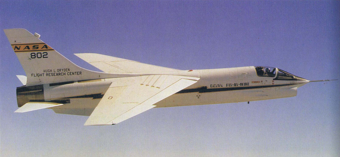
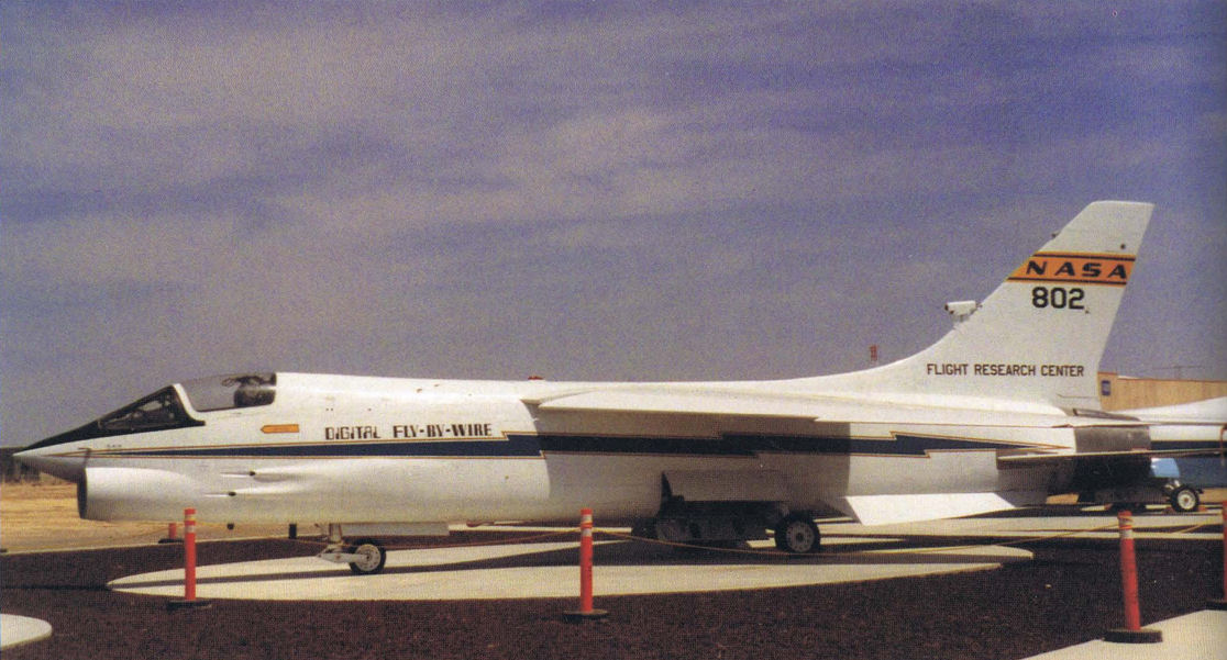
The F-8 Fly-By-Wire testbed was one of a long list of aircraft investigating this unique technology.
Самолёты на фотографии: Vought F8U / F-8 Crusader - США - 1955
-

The F-8 Fly-By-Wire testbed aircraft is now on display at NASA Dryden at Edwards Air Force Base.
Самолёты на фотографии: Vought F8U / F-8 Crusader - США - 1955
-

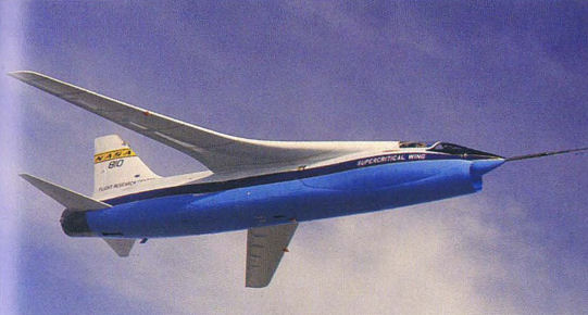
Two unique F-8 testbeds. The F-8 Fly-By-Wire testbed flies in formation with its F-8 brother, the supercritical wing testbed.
Самолёты на фотографии: Vought F8U / F-8 Crusader - США - 1955
-

На самолете F-8A SCW в исследовательских целях установили суперкритическое крыло, верхняя поверхность которого выполнена более пологой, а нижняя - более искривленной. Такое крыло исключает появление местных скачков.
The F-8 Supercritical Wing test aircraft in flight. The new wing had a typical airliner-type platform. Note also the fuselage mounted fairings to reduce drag.Самолёты на фотографии: Vought F8U / F-8 Crusader - США - 1955
-

The F-8 testbed is now on display at NASA Dryden at Edwards Air Force Base.
Самолёты на фотографии: Vought F8U / F-8 Crusader - США - 1955
-

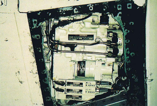
The so-called EPAD program used an F/A -18 testbed aircraft to test an electrically-powered activation system. This photo shows the installation details.
Самолёты на фотографии: McDonnell Douglas F/A-18A Hornet - США - 1978
-

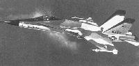
This F/A-18 pre-production fighter aircraft was modified for the HARV Program. The program started in 1987 and was continuing into the 1990s. Clearly visible is the paddle actuation system for deflecting engine exhaust.
Самолёты на фотографии: McDonnell Douglas F/A-18A Hornet - США - 1978
-

The capability to maneuver at high angles-of-attack received high attention in the 1990s with the HARV program which was a multi-center NASA program.
Самолёты на фотографии: McDonnell Douglas F/A-18A Hornet - США - 1978
-

A majority of the high angle-of-attack modifications were done on the rear portion of the F/A-18's fuselage as is clearly evident in this photo.
Самолёты на фотографии: McDonnell Douglas F/A-18A Hornet - США - 1978
-

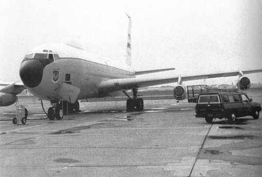
An earlier configuration of the Airborne Laser Program is shown during a flight test.
Самолёты на фотографии: Boeing KC-135 Stratotanker / C-135 Stratolifter - США - 1956
-

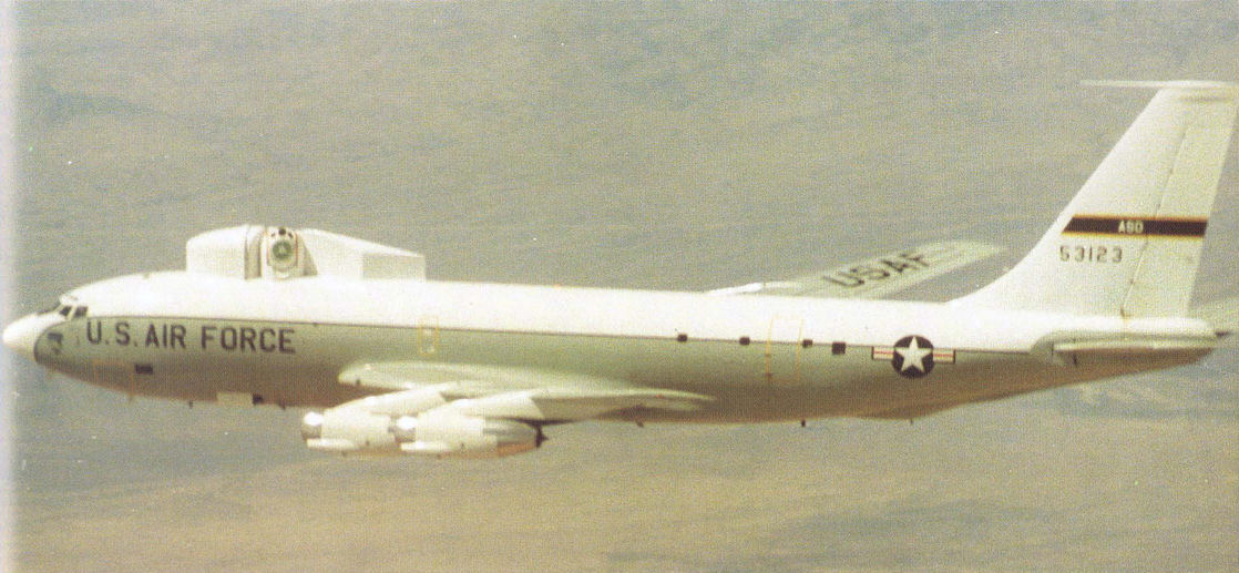
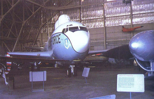
The "5" in the tail number of this C-135 indicates 1955, which makes this plane, which served as the testbed for the Airborne Laser Program, one of the oldest of the type.
Самолёты на фотографии: Boeing KC-135 Stratotanker / C-135 Stratolifter - США - 1956
-

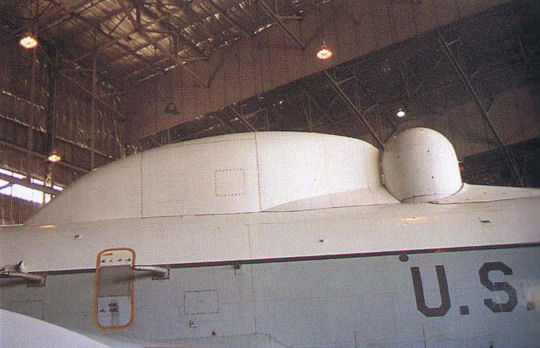
This particular aircraft was easily identifiable from its pair of domes on top of the fuselage.
Самолёты на фотографии: Boeing KC-135 Stratotanker / C-135 Stratolifter - США - 1956
-

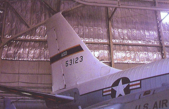
The Airborne Laser Program testbed aircraft now resides quietly in the Air Force Museum.
Самолёты на фотографии: Boeing KC-135 Stratotanker / C-135 Stratolifter - США - 1956
-

This KC-135A testbed aircraft tested new engine systems and was the ABIT test aircraft during its career.
Самолёты на фотографии: Boeing KC-135 Stratotanker / C-135 Stratolifter - США - 1956
-

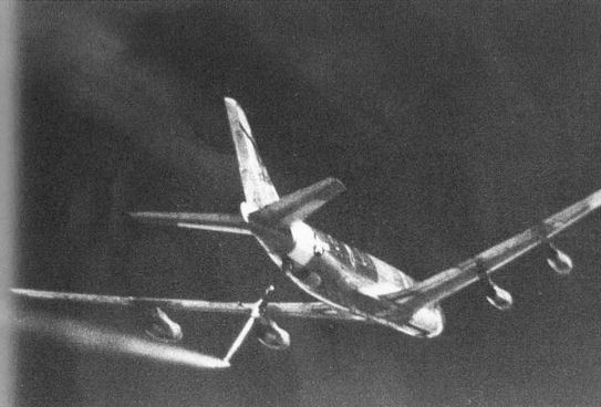
This KC-135 icing aircraft lets loose a spray of icing fluid to check out the trailing aircraft.
Самолёты на фотографии: Boeing KC-135 Stratotanker / C-135 Stratolifter - США - 1956
-

The LASERCOM modification of this C-135 testbed aircraft was used to transmit data between satellites and ground and airborne users.
Самолёты на фотографии: Boeing KC-135 Stratotanker / C-135 Stratolifter - США - 1956
-

The interestingly-painted fuselage of this C-135 participated in the HAVE LACE laser communications program.
Самолёты на фотографии: Boeing KC-135 Stratotanker / C-135 Stratolifter - США - 1956
-

The configuration of the icing mechanism on this KC-135 is clearly visible in this photo.
Самолёты на фотографии: Boeing KC-135 Stratotanker / C-135 Stratolifter - США - 1956
-
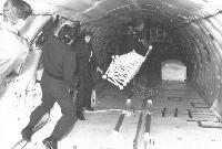
One of the most famous KC-135 testbed aircraft was called the "Weightless Wonder" and served to train astronauts on the effects of weightlessness.
Самолёты на фотографии: Boeing KC-135 Stratotanker / C-135 Stratolifter - США - 1956
-
This artist's concept shows the installation of wingtip winglets on a KC-135 testbed aircraft. The fuel-saving concept was never incorporated on the Air Force fleet, but it's used extensively on the commercial airline fleet.
Самолёты на фотографии: Boeing KC-135 Stratotanker / C-135 Stratolifter - США - 1956
-

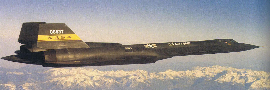
The SR-71 was used for many years as a high-flying reconnaissance aircraft, but when it was recently retired, three of the Black Birds were transferred to NASA for research work as flying testbeds.
Самолёты на фотографии: Lockheed SR-71 - США - 1964
-

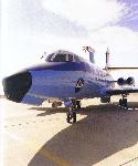
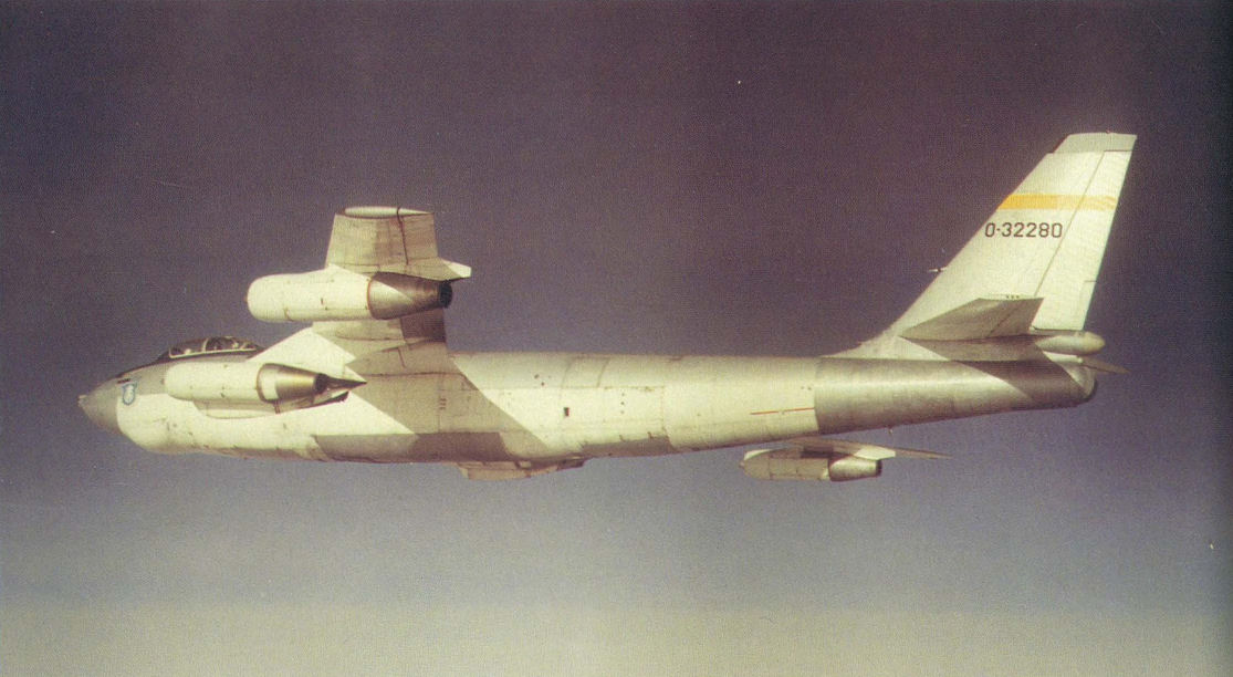
One of the earliest testbed aircraft to investigate fly-by-wire capabilities was this B-47. Presently, this plane is displayed in the Air Force Museum where it has been repainted in operational colors.
Самолёты на фотографии: Boeing B-47 Stratojet - США - 1947
-

At the completion of this program (Fly-By-Wire Research/Demonstration) the aircraft appeared as shown here. Note the glass window in the nose and the air inlets under the tail still on the aircraft today.
Самолёты на фотографии: Boeing B-47 Stratojet - США - 1947
-

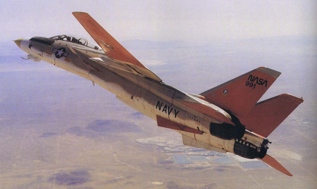
This F-14A testbed was modified with the so-called Aileron-Rudder Interconnect System which investigated new high angle-of-attack flight techniques.
Самолёты на фотографии: Grumman F-14 Tomcat - США - 1970
-

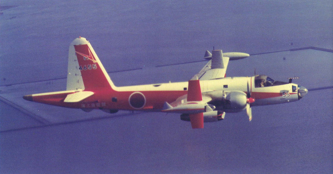
P-2 Variable Stability Aircraft in flight. The aircraft performed airborne simulation and research.
Самолёты на фотографии: Lockheed Neptune P2V - США - 1945
-

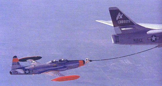
NT-33 performing mid-air refueling from a Navy KA-3 tanker in the mid-1970s.
Самолёты на фотографии: Douglas A-3 Skywarrior - США - 1952Lockheed T-33A - США - 1948
-

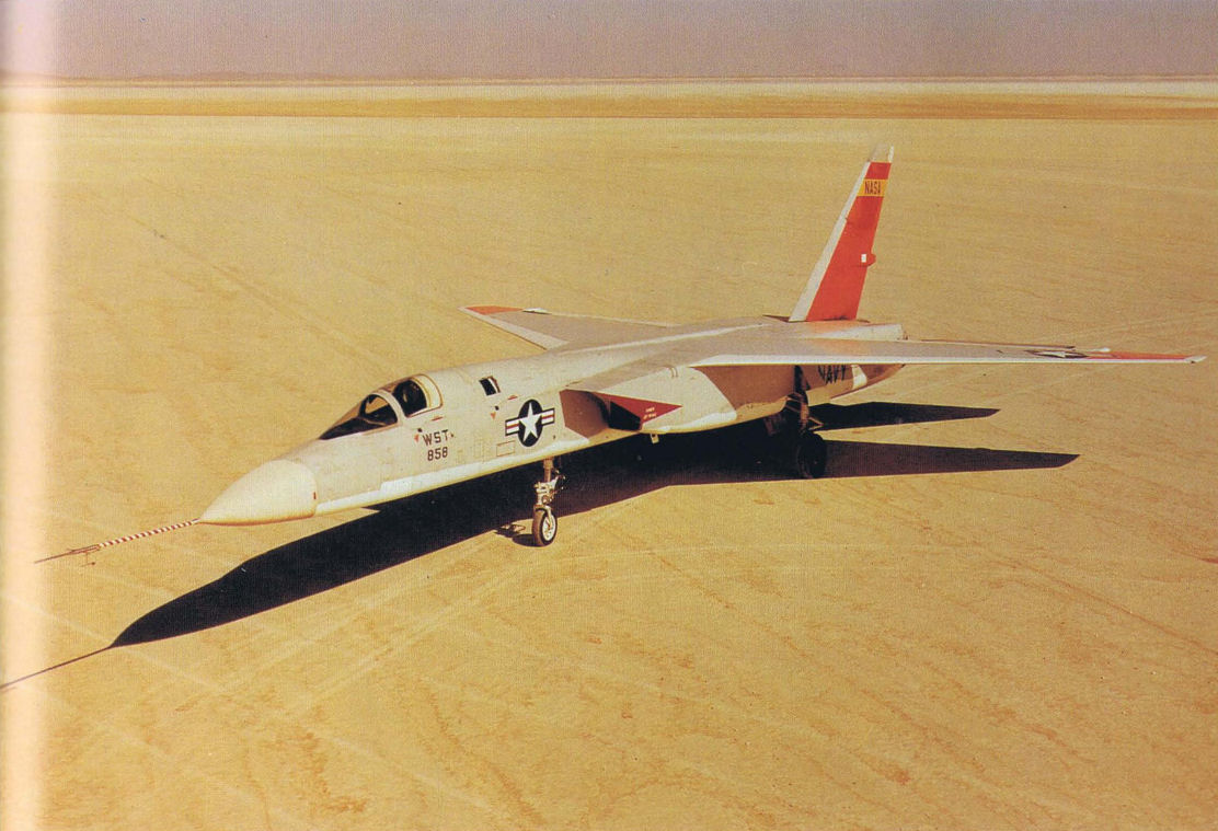
This Navy A-5A Vigilante was used by NASA to simulate approaches for the ill-fated American Supersonic Transport program.
Самолёты на фотографии: North American A-5 Vigilante - США - 1958
-

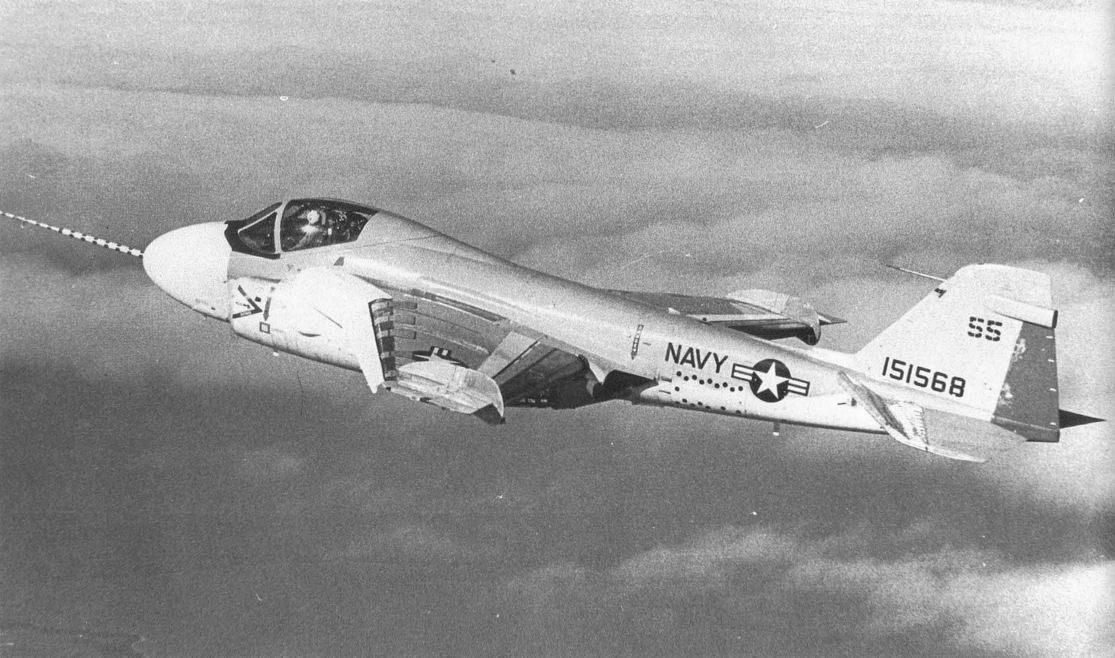
This Navy A-6A bomber was modified in the late 1970s time period to simulate low-speed approaches. The modified trailing edges are not visible, but the stall fences are.
Самолёты на фотографии: Grumman A-6 Intruder - США - 1960
-
The modifications to this testbed aircraft can be seen under the twin engine exhausts. The concept was to trap bleed air from the exhausts and then direct the air through special slots on the trailing edge of each wing.
Самолёты на фотографии: Grumman A-6 Intruder - США - 1960
-

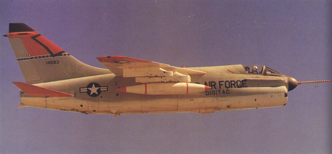
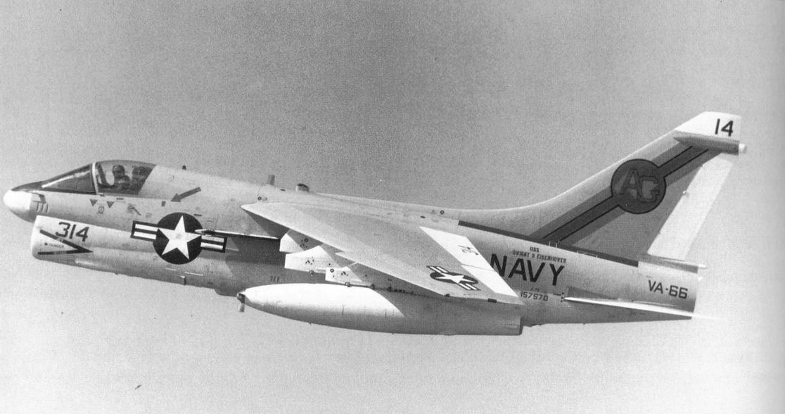
The DIGITAC Program used the Corsair II fighter as the testbed aircraft. Besides the high-visibility marking and the test pod being carried, the A-7 appears to be quite normal.
Самолёты на фотографии: Vought A-7 Corsair II - США - 1965
-

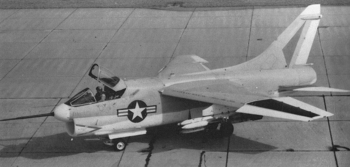
During this phase of the DIGITAC Program, the A-7 testbed aircraft had an interesting test pattern on the side of its fuselage.
Самолёты на фотографии: Vought A-7 Corsair II - США - 1965
-

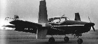
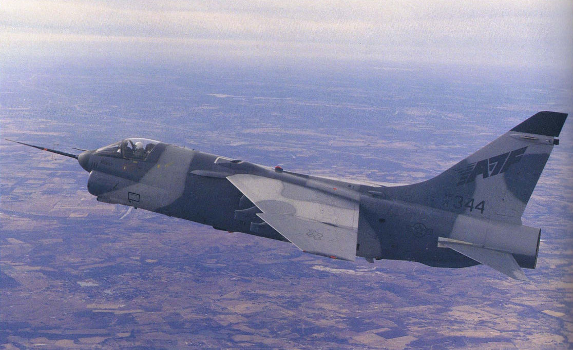
Production of one of the two YF-7F prototypes at LTV Aircraft Products Group.
Самолёты на фотографии: Vought A-7 Corsair II - США - 1965
-

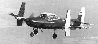
Для улучшения маневренности YA-7F перед крылом смонтировали небольшие наплывы. Доработка закрылков позволила снизить посадочную скорость (примерно на 12 км/ч) и сократить дистанцию пробега примерно на 20%. 1989г.
The YA-7A took on a new design grace. Here's a shot of the prototype during flight testing.Самолёты на фотографии: Vought A-7 Corsair II - США - 1965
-

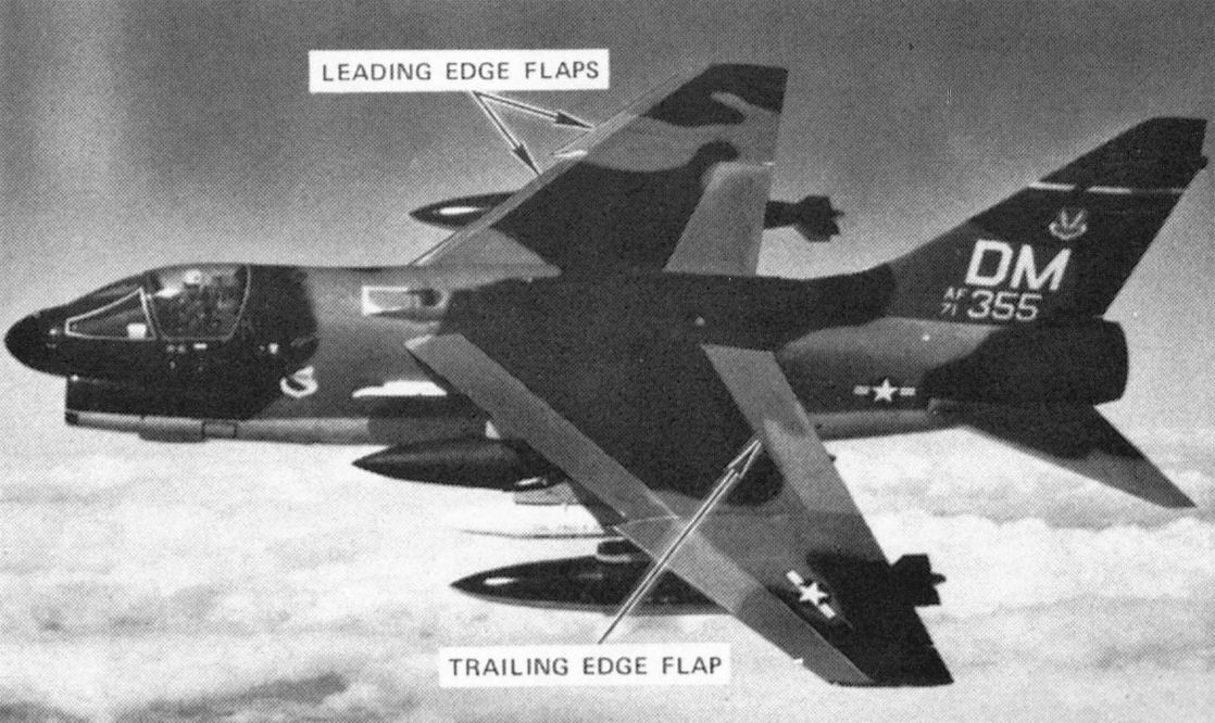
Increased maneuverability was the goal of this A-7 testbed modification with the addition of leading and trailing edge flaps.
Самолёты на фотографии: Vought A-7 Corsair II - США - 1965
-

A Corsair II, like this operational U.S. Navy version, was selected by the Air Force for significant modification as the YA-7F Prototype Fighter. Air Force versions were used for the actual modifications.
Самолёты на фотографии: Vought A-7 Corsair II - США - 1965
-

This A-7D testbed, along with seven other operational versions, was fitted with composite material outer wing panels.
Самолёты на фотографии: Vought A-7 Corsair II - США - 1965
-

One of the first investigations into the benefits of low L/D flight was accomplished by this F-102 delta-wing fighter.
Самолёты на фотографии: Convair F-102 Delta Dagger - США - 1953
-
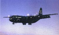
The Lockheed HTTB testbed developed many new technologies for tactical airlift concepts.
Самолёты на фотографии: Lockheed C-130 Hercules - США - 1954
-

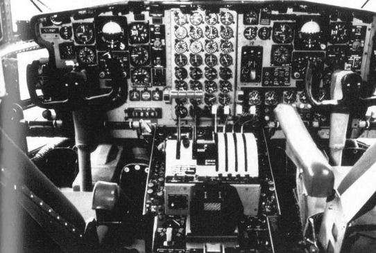
Standard C-130 instrument panel appears to be a montage of instruments compared to the RAMTlP cockpit design.
Самолёты на фотографии: Lockheed C-130 Hercules - США - 1954
-

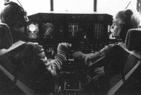
The actual RAMTIP cockpit.
Самолёты на фотографии: Lockheed C-130 Hercules - США - 1954
-

В исследовательских целях использовалось несколько самолетов, обозначенных как JF-100C
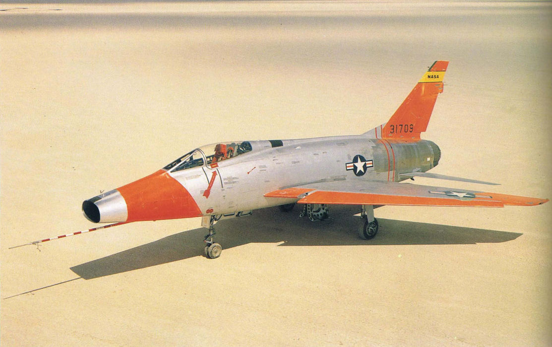
NASA modified an F-100 Super Sabre to the JF-100 during the 1960s to test a number of flight regimes. It's shown here on the lake bed at Edwards Air Force base.Самолёты на фотографии: North American F-100 Super Sabre - США - 1953
-

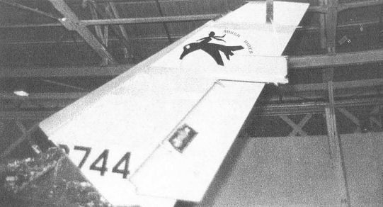
Регистрационный номер: FW-744 [3] Rough Rider was the name given to a program for turbulence testing. The logo can be seen on the tail of the F-100 testbed aircraft.
Самолёты на фотографии: North American F-100 Super Sabre - США - 1953
-

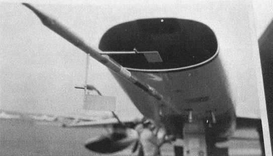
Регистрационный номер: FW-744 [3] A special probe, with sideslip and angle-of-attack sensors, was carried on the forward section of the F-100 turbulence test aircraft.
Самолёты на фотографии: North American F-100 Super Sabre - США - 1953
-

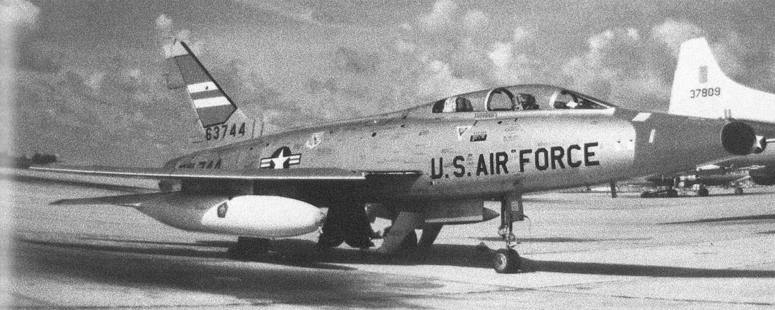
Регистрационный номер: FW-744 [3] This particular F-100 testbed aircraft was used during the 1960s in wind turbulence testing.
Самолёты на фотографии: North American F-100 Super Sabre - США - 1953
-

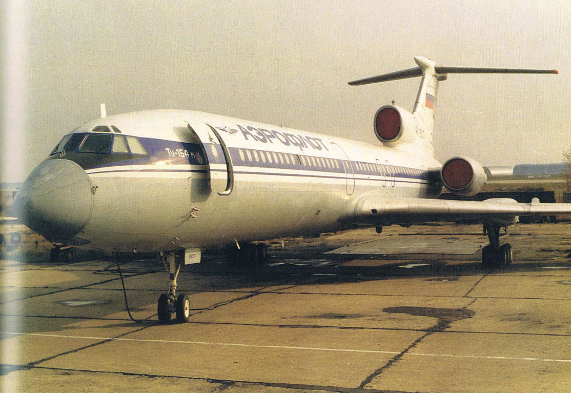
From the outside, the Tu-154M in-flight simulator appears similar to an Aeroflot airliner.
Самолёты на фотографии: Туполев Ту-154 - Россия - 1968
-

Tu-154M inflight simulator cockpit. Note the heads-up display, CRT display, experimental control yoke and side stick.
Самолёты на фотографии: Туполев Ту-154 - Россия - 1968
-

NT-33 over Edwards Air Force Base on a test pilot instruction flight in the mid-1980s.
Самолёты на фотографии: Lockheed T-33A - США - 1948
-
One of the unique modifications to the NT-33 was the installation of tip-tank mounted speed brakes.
Самолёты на фотографии: Lockheed T-33A - США - 1948
-
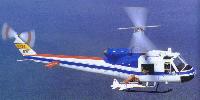
Another aircraft model, this time an F-5, is carried by the Bell 204 helicopter.
Самолёты на фотографии: Bell UH-1 Iroquois / Model 204 - США - 1956Northrop F-5A Freedom Fighter - США - 1963
-
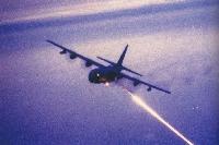
The C-130 Gunship was developed using a C-130 testbed aircraft at the 4950th Test Wing at Wright Patterson AFB.
Самолёты на фотографии: Lockheed AC-130 Spectre - США - 1959
-
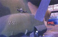
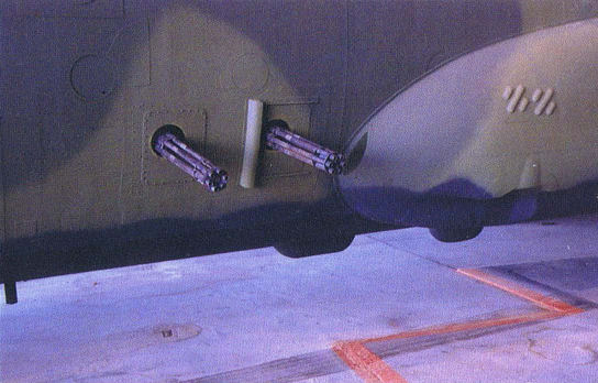
This photo shows the mini-gun and cannon which are located above, and behind the landing gear, respectively.
Самолёты на фотографии: Lockheed AC-130 Spectre - США - 1959
-

Shown here on the C-130 Gunship testbed are the set of Gatling Guns located just ahead of the landing gear fairing. This aircraft can be viewed at the Air Force Museum.
Самолёты на фотографии: Lockheed AC-130 Spectre - США - 1959
-

If you look closely on the wing, you can pick out the supercritical airfoil shape.
Самолёты на фотографии: General Dynamics F-111 Aardvark - США - 1964
-

After completion of the TACT Program, gloves were installed to investigate natural laminar flow.
Самолёты на фотографии: General Dynamics F-111 Aardvark - США - 1964
-

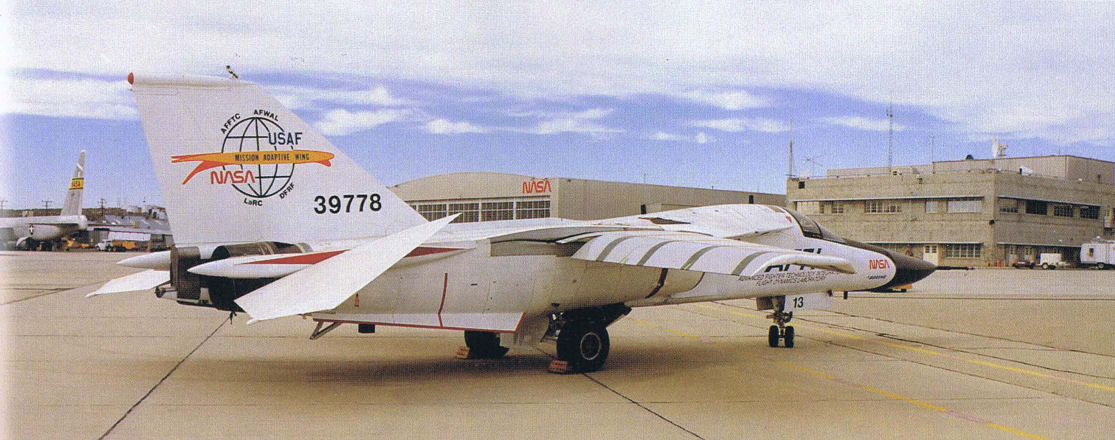
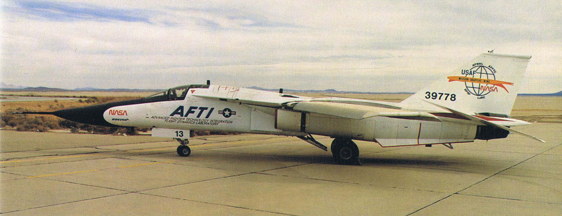
The AFTI/F-111A at Edwards prior to first flight. The test programme is managed by the USAF’s Flight Dynamics Laboratory, part of the Aeronautical Systems Division's Air Force Wright Aeronautical Laboratories (AFWAL), in collaboration with NASA's Dryden Flight Research Facility (DFRF).
Самолёты на фотографии: General Dynamics F-111 Aardvark - США - 1964
-

This view of the AFTI F-111 shows its leading edges smoothly deflected and the trailing edges slightly deflected.
Самолёты на фотографии: General Dynamics F-111 Aardvark - США - 1964
-
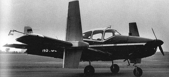
UTSI Navion on the ground. Note the wing-mounted angle-of-attack and side slip sensors.
Самолёты на фотографии: North American Navion / L-17 (Ryan) - США - 1946
-
The UTSI Navion in flight. Note the tuffs of yarn on the starboard side-force surface to study airflow.
Самолёты на фотографии: North American Navion / L-17 (Ryan) - США - 1946
-

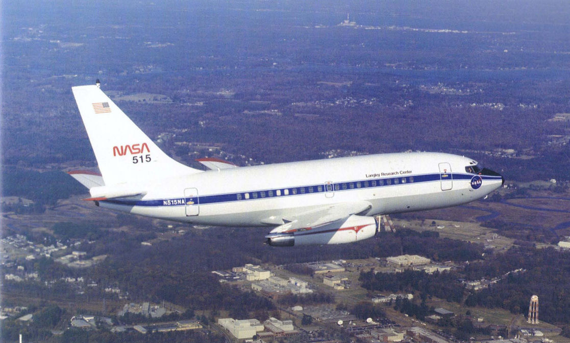
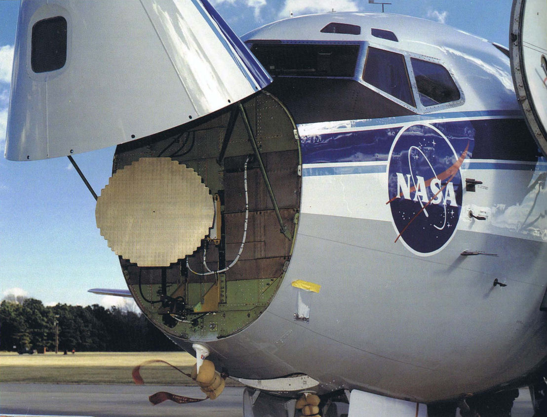
Регистрационный номер: N515NA [3] A highly-modified Boeing 737 was designed as the Terminal-Configured Vehicle (TCV) which contained a complete second cockpit within the fuselage.
Самолёты на фотографии: Boeing Boeing 737 - США - 1967
-

Регистрационный номер: N515NA [3] A radar is contained under the radome of the Terminal-Configured Vehicle (TCV).
Самолёты на фотографии: Boeing Boeing 737 - США - 1967
-
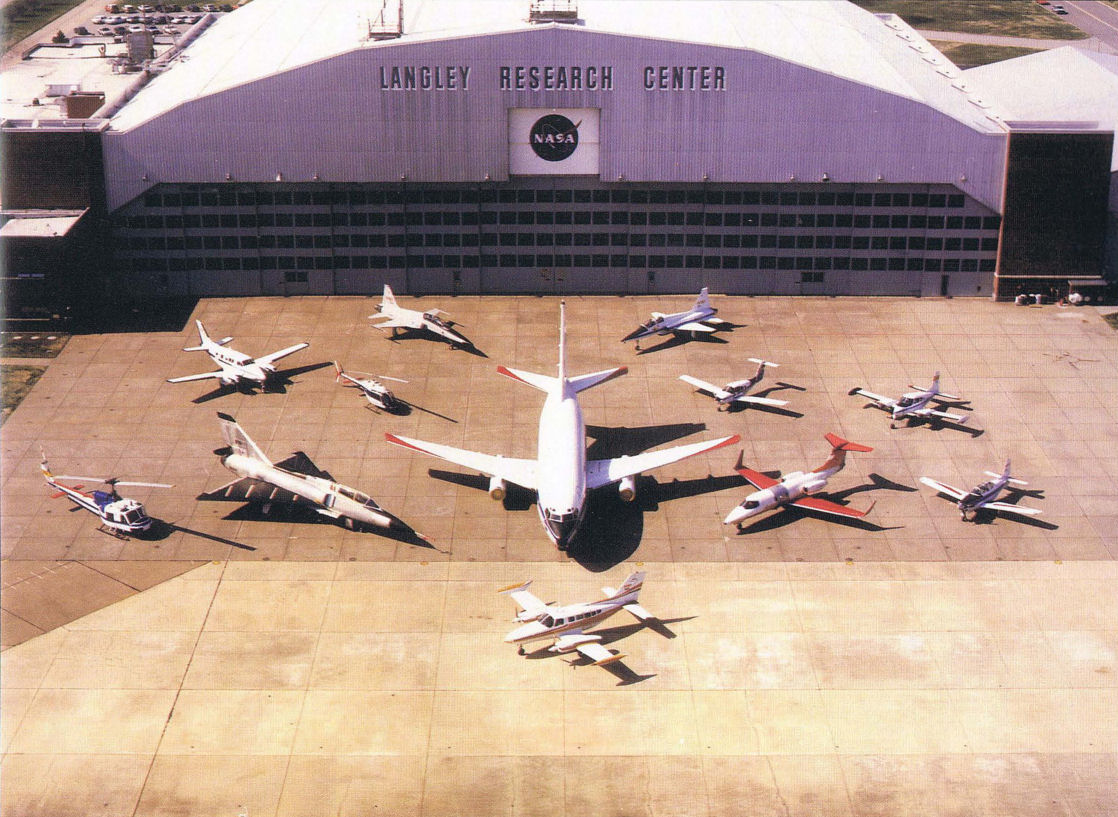
Регистрационный номер: N515NA [3], N566NA [2] The NASA Langley organization has a number of testbed aircraft including a Cessna 402B, 172 Skyhawk, T-34C, PA-28RT, and Learjet.
Самолёты на фотографии: Beechcraft Model 45 / T-34 Mentor - США - 1948Boeing Boeing 737 - США - 1967Cessna 411/401/402/421/414/404 - США - 1962Learjet Learjet 28 / 29 Longhorn - США - 1977Piper Cherokee PA-28 - США - 1960
-

The T-34 performed laminar control studies in its tenure at NASA Langley.
Самолёты на фотографии: Beechcraft Model 45 / T-34 Mentor - США - 1948
-
The YF-17 served as a prototype during competition with the YF-16 in the Air Force Lightweight Fighter competition. The YF-17 aircraft lost that competition, but it would then serve as the testbed for the Navy F/A-18 fighter.
Самолёты на фотографии: Northrop YF-17 Cobra - США - 1974
-
An artist's concept of the F-18 Hornet fighter that would evolve from the YF-17 testbed prototype.
Самолёты на фотографии: Northrop YF-17 Cobra - США - 1974
-

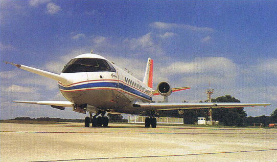
The ATLAS pod appears similar to a belly-mounted external fuel tank.
Самолёты на фотографии: Dassault Falcon 20 / 30 - Франция - 1963
-

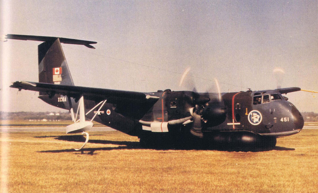
In a joint U.S./Canadian test program, this XC-8A was modified with an air cushion system for landings on all types of terrain. Note the wingtip floats for water tests.
Самолёты на фотографии: De Havilland Canada DHC-5 Buffalo / C-8 - Канада - 1964
-

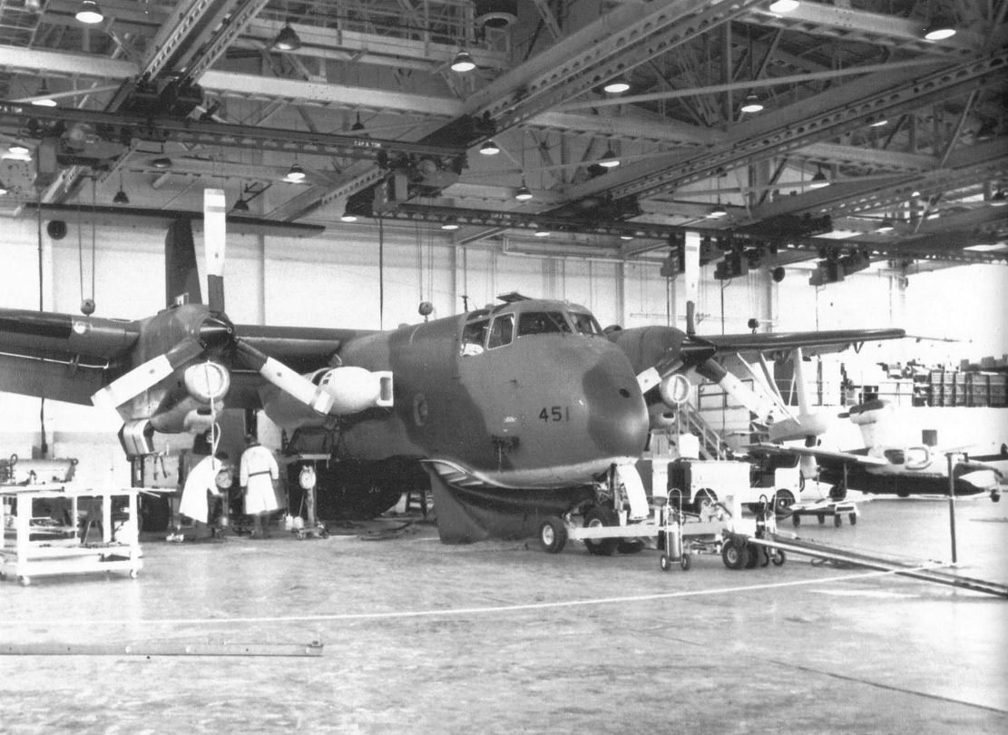
The XC-8A testbed aircraft during maintenance at Wright Patterson AFB. The air cushion landing system and the auxiliary turbine under the right wing root are clearly visible.
Самолёты на фотографии: De Havilland Canada DHC-5 Buffalo / C-8 - Канада - 1964
-
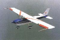
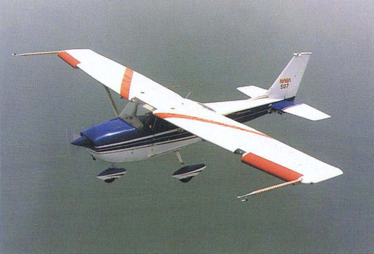
This Skyhawk testbed has been serving since 1972. It's shown here carrying wing tufting, leading edge glove and twin instrumentation booms.
Самолёты на фотографии: Cessna 172 Skyhawk / 182 Skyline / T-41 - США - 1955
-
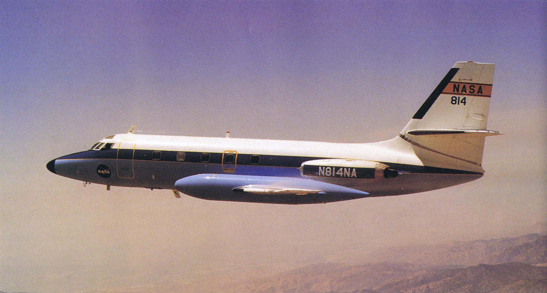
Регистрационный номер: N814NA [2] The GPAS aircraft, early in its career, prior to the addition of its fuselage-mounted pylon.
Самолёты на фотографии: Lockheed C-140 JetStar - США - 1957
-

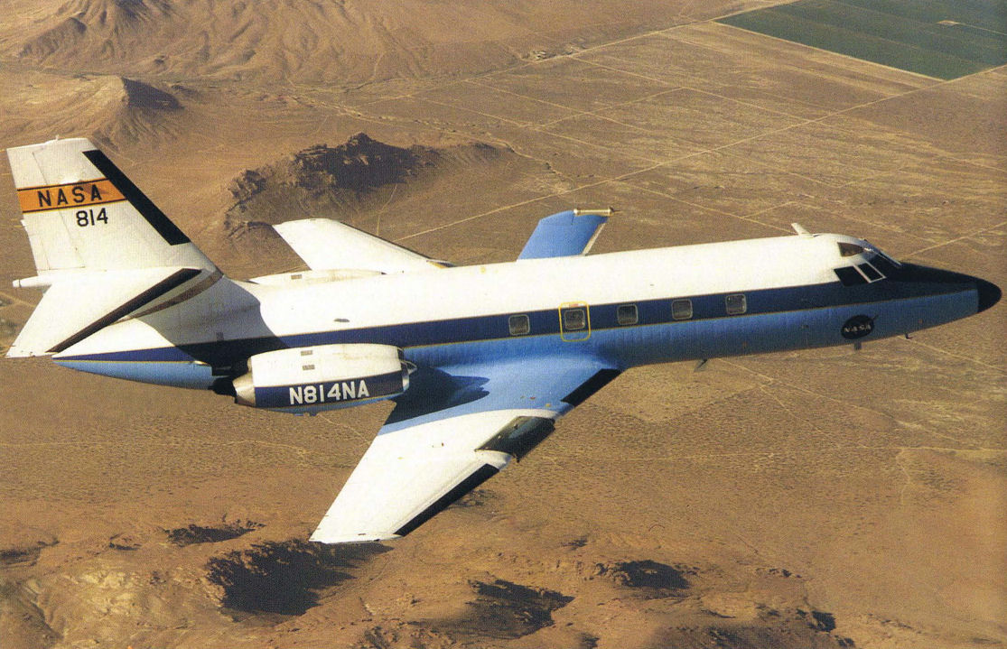
Регистрационный номер: N814NA [2] GPAS aircraft performing laminar flow studies. Notice that the wing-mounted fuel tanks have been removed.
Самолёты на фотографии: Lockheed C-140 JetStar - США - 1957
-
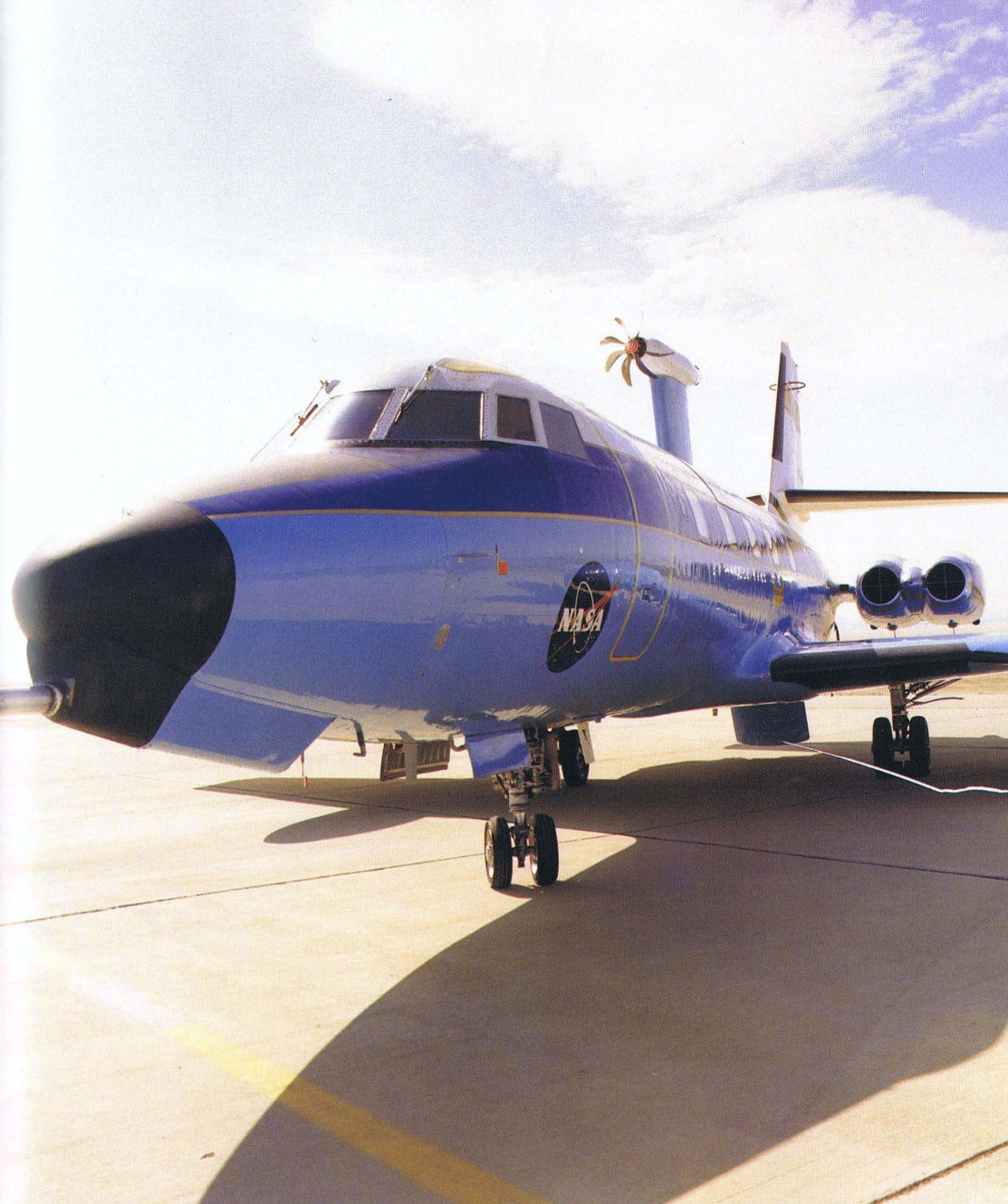
The GPAS with a scale model unducted fan mounted on the fuselage pylon. Also note the instrumentation boom mounted below the nose.
Самолёты на фотографии: Lockheed C-140 JetStar - США - 1957
-

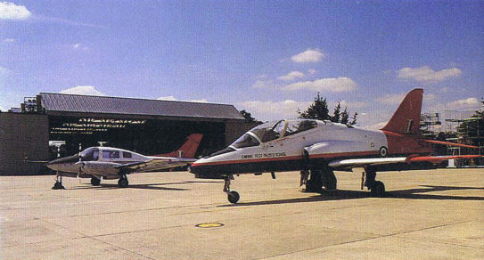
Empire Test Pilot School's variable stability ASTRA Hawk, with the older variable stability Basset in the background. The number "1" on the vertical tail is just about the only external feature distinguishing this aircraft from the school's other Hawk aircraft.
Самолёты на фотографии: Beagle Basset / B.206 - Великобритания - 1961Hawker-Siddeley Hawk / HS.1182 - Великобритания - 1972
-

Expandable tire program. C-131 landing with expandable/deflatable tires.
Самолёты на фотографии: Convair CV-240 Convair-Liner / C-131 / C-340 / C-440 - США - 1946
-

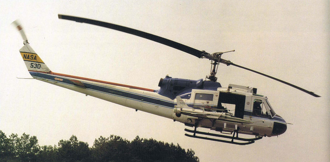
This Bell 204 NASA helicopter is used as a carrier testbed aircraft, shown here carrying a model of the X-29 research aircraft.
Самолёты на фотографии: Bell UH-1 Iroquois / Model 204 - США - 1956Grumman X-29 - США - 1984
-

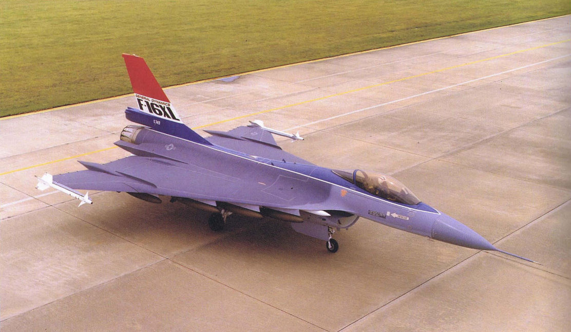
It might not look much like the F-16 from which it was derived, but the bat-appearing F-16XL started from a standard F-16 production aircraft.
Самолёты на фотографии: General Dynamics F-16XL - США - 1982
-

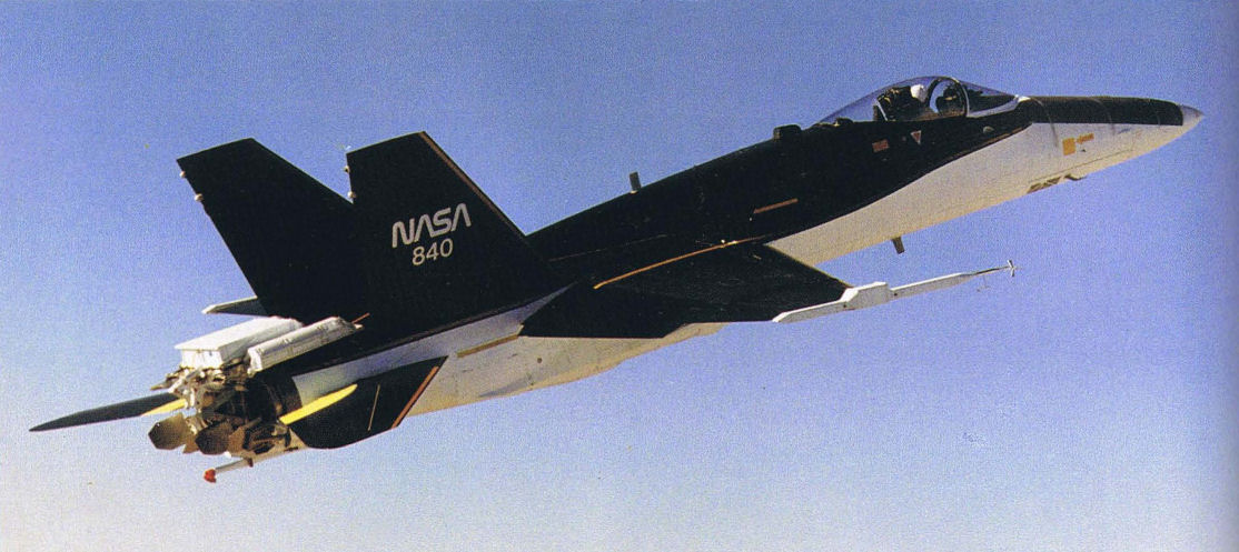
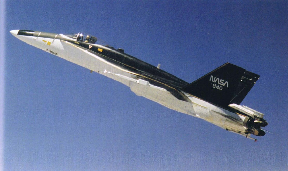
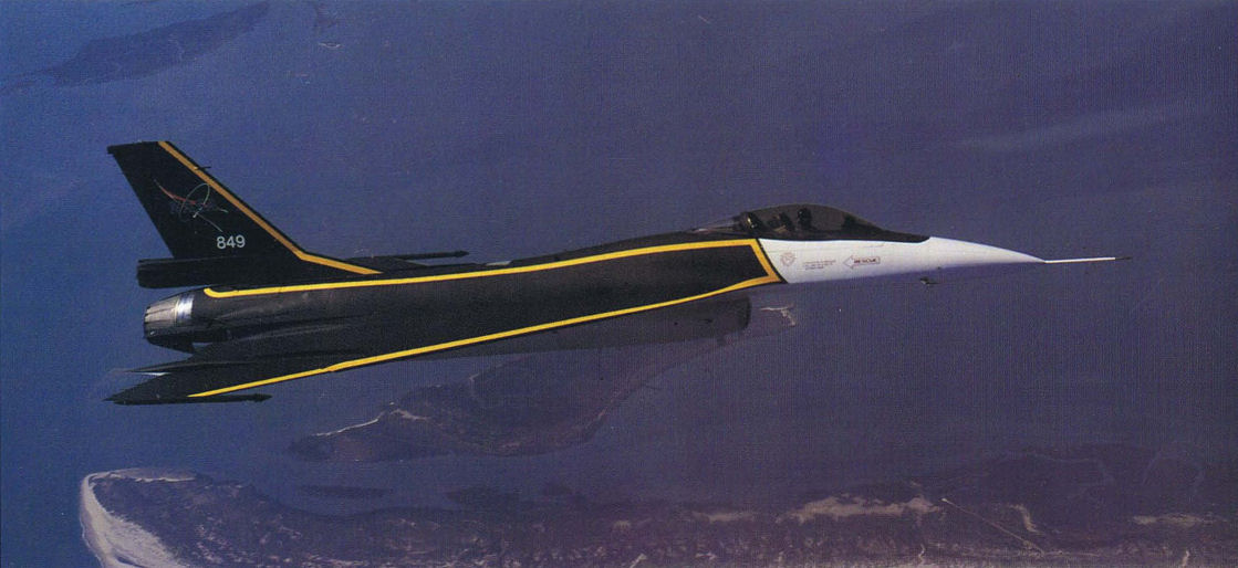
In 1993, NASA used one of the F-16XL testbed aircraft to support the agency's High Speed Research (HSR) program. For the test, the craft received a dramatic new black and gold paint scheme.
Самолёты на фотографии: General Dynamics F-16XL - США - 1982
-

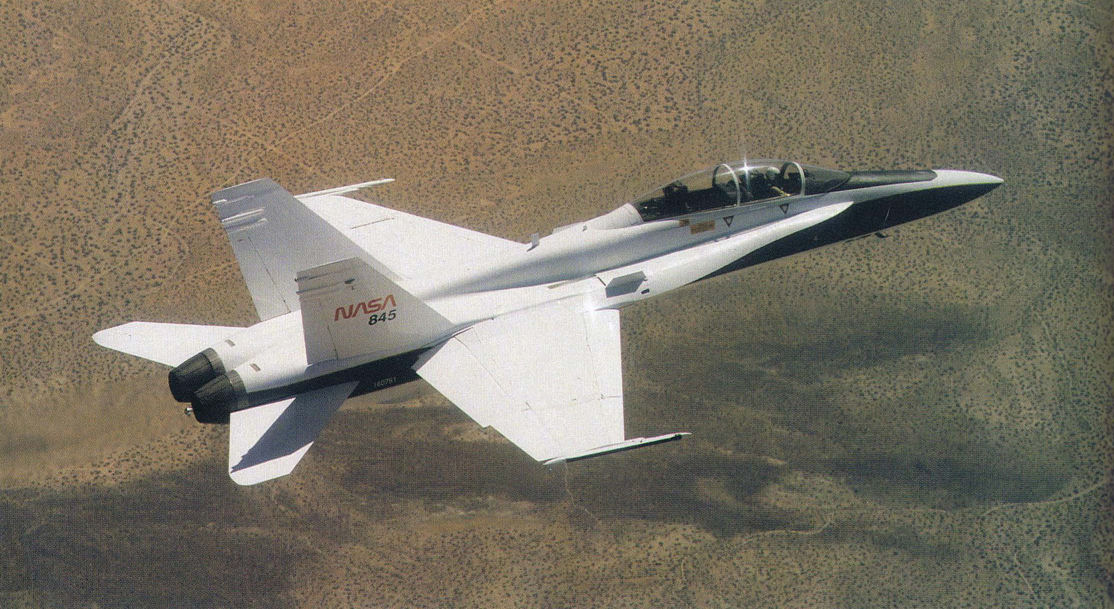
This NASA F/A-18, specially modified to test the newest and most advanced system technologies, on its first flight in May 1993, at the Dryden Flight Research Center, Edwards, California
Самолёты на фотографии: McDonnell Douglas F/A-18B Hornet - США - 1979
-

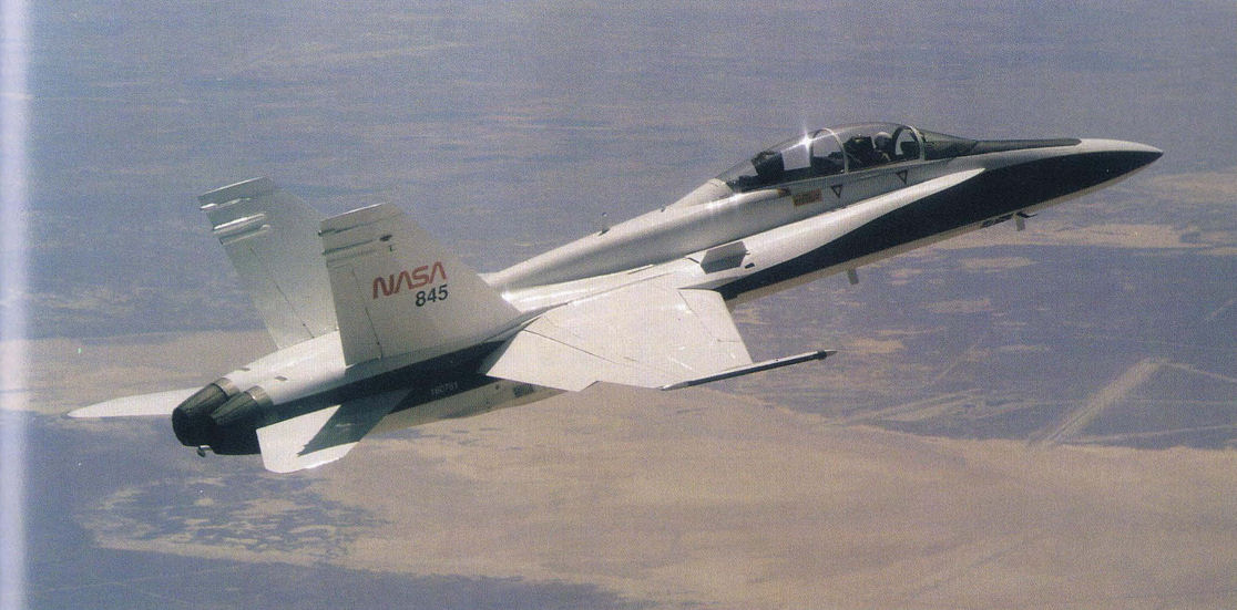
The F/A-18 SRA aircraft evaluates technologies that will benefit both civilian and military aircraft.
Самолёты на фотографии: McDonnell Douglas F/A-18B Hornet - США - 1979
-

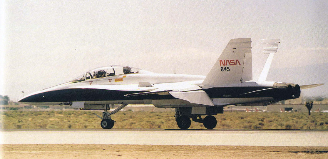
Other that the external markings, there is nothing to identify this F/A-18 from its operational brothers.
Самолёты на фотографии: McDonnell Douglas F/A-18B Hornet - США - 1979
-

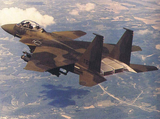
The Strike Eagle Demonstrator took on several looks, shown here in complete camouflage paint.
Самолёты на фотографии: McDonnell Douglas F-15E Strike Eagle - США - 1986
-

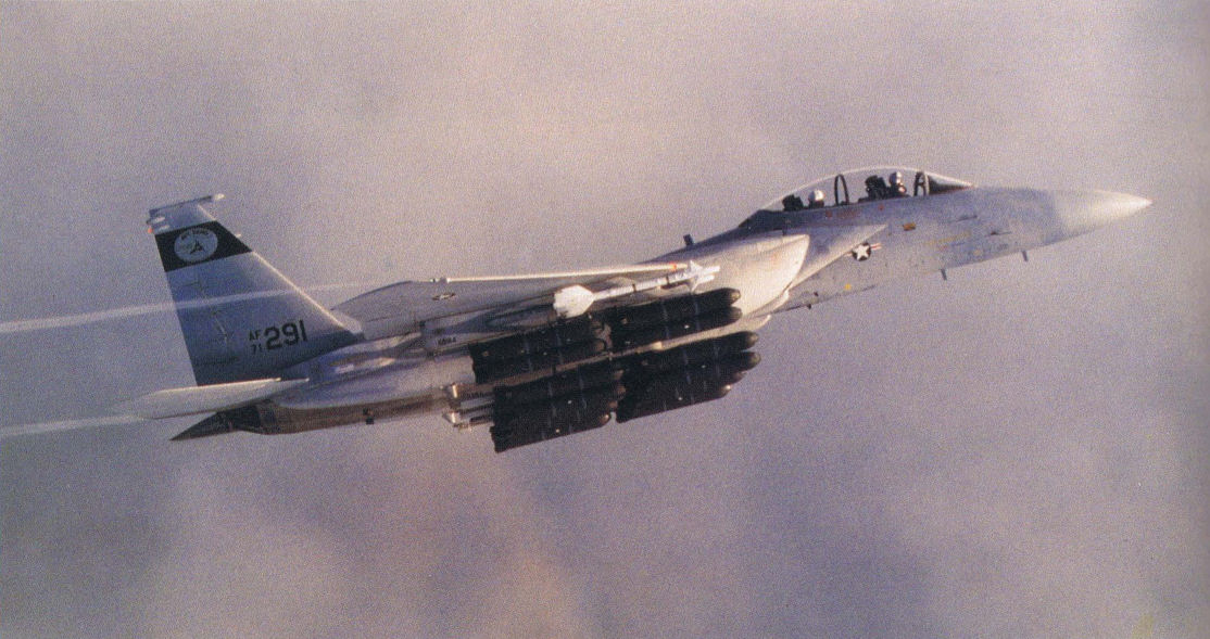
A production F-15B was modified to serve as the demonstrator for the F-15E Strike Eagle shown here with a full air-to-ground ordnance load.
Самолёты на фотографии: McDonnell Douglas F-15E Strike Eagle - США - 1986
-

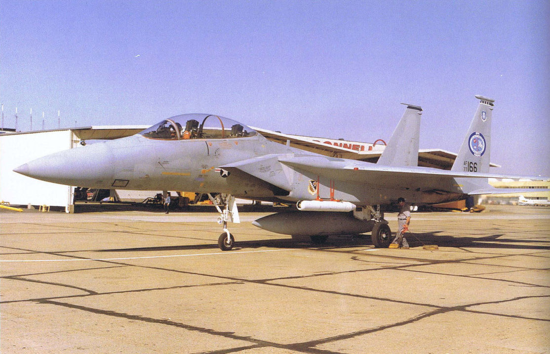
This F-15B was initially modified to the IFFC configuration.
Самолёты на фотографии: McDonnell Douglas F-15B/D Eagle - США - 1972
-

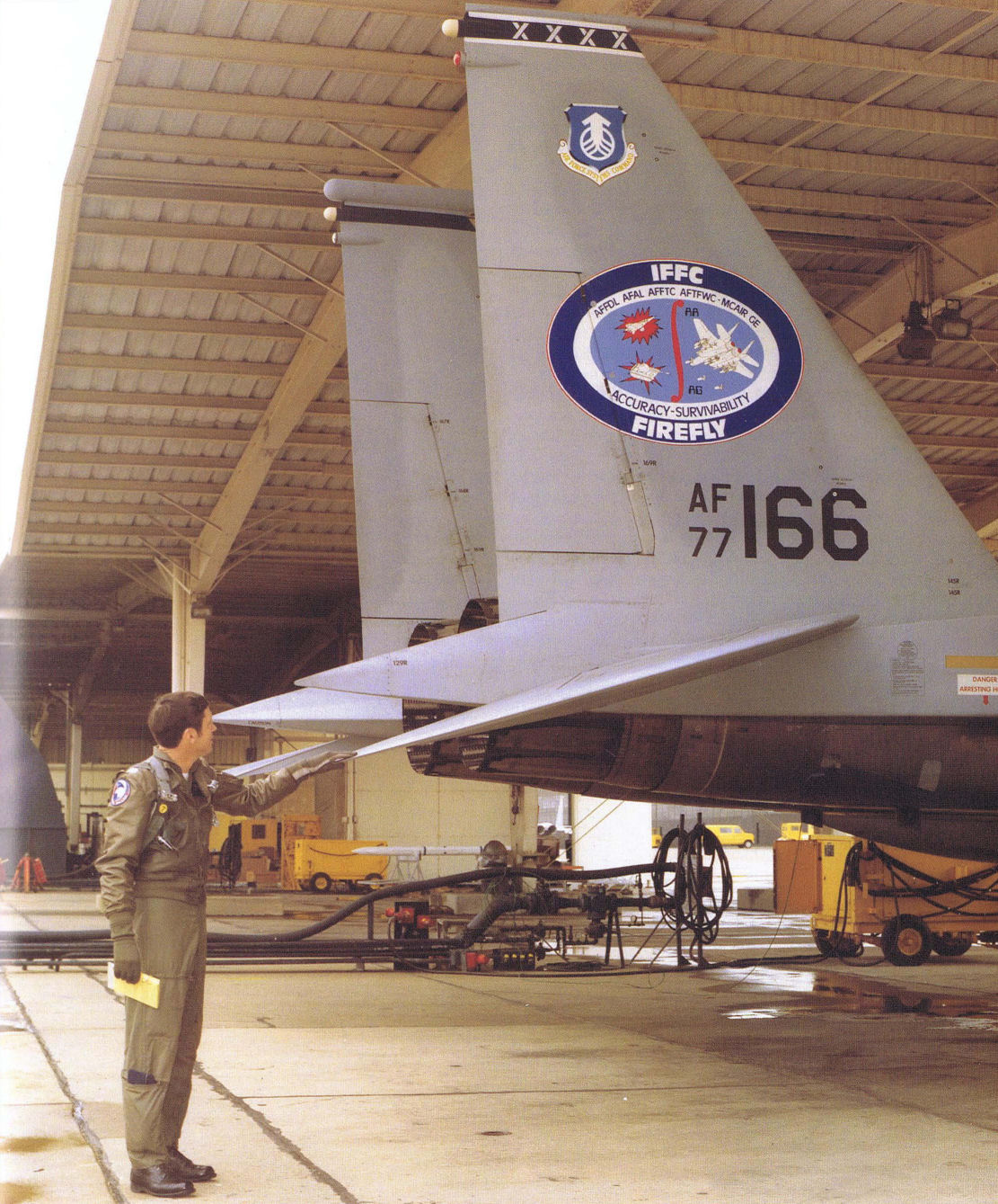
There was no mistaking the IFFC-configured F-15B which carried this distinct logo on the tail.
Самолёты на фотографии: McDonnell Douglas F-15B/D Eagle - США - 1972
-

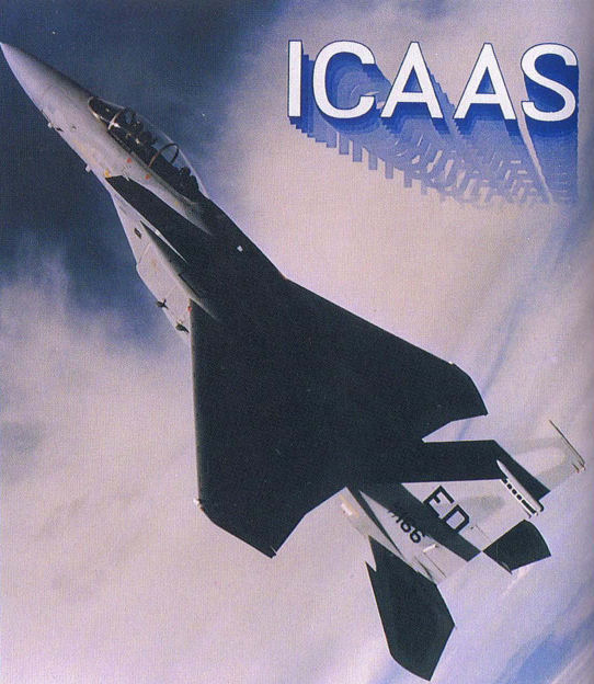
The final configuration of this testbed with the so-called ICAAS program. The configuration could not be identified externally by any distinctive markings. The ICAAS program was canceled before completion.
Самолёты на фотографии: McDonnell Douglas F-15B/D Eagle - США - 1972
-

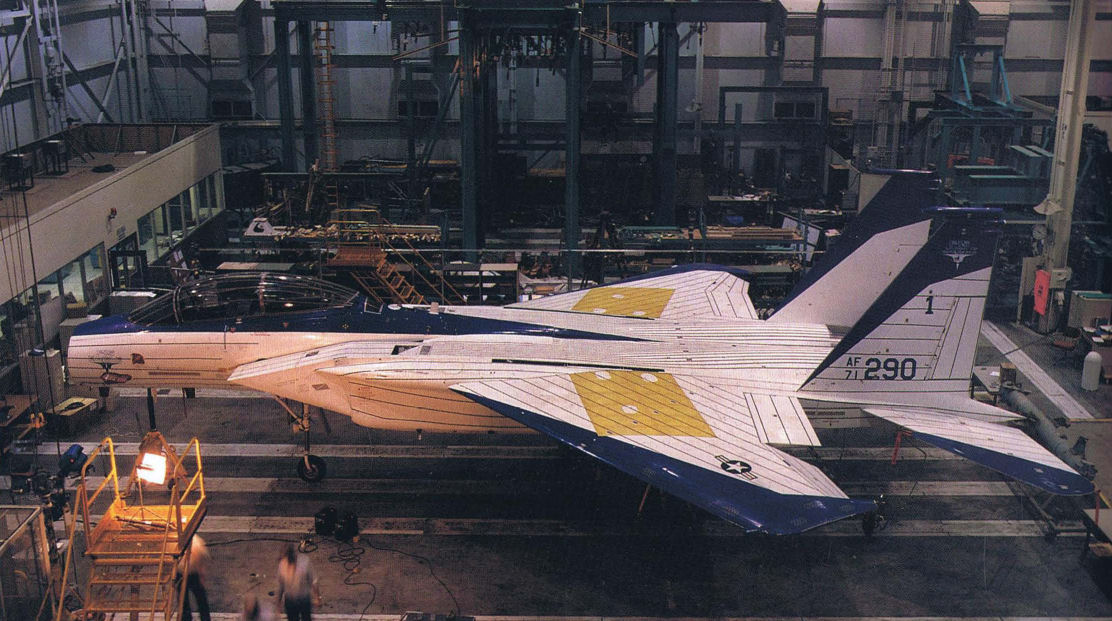
The F-15 STOL/MTD is shown under construction at the McDonnell Douglas facility at St. Louis.
Самолёты на фотографии: McDonnell Douglas F-15B/D Eagle - США - 1972
-

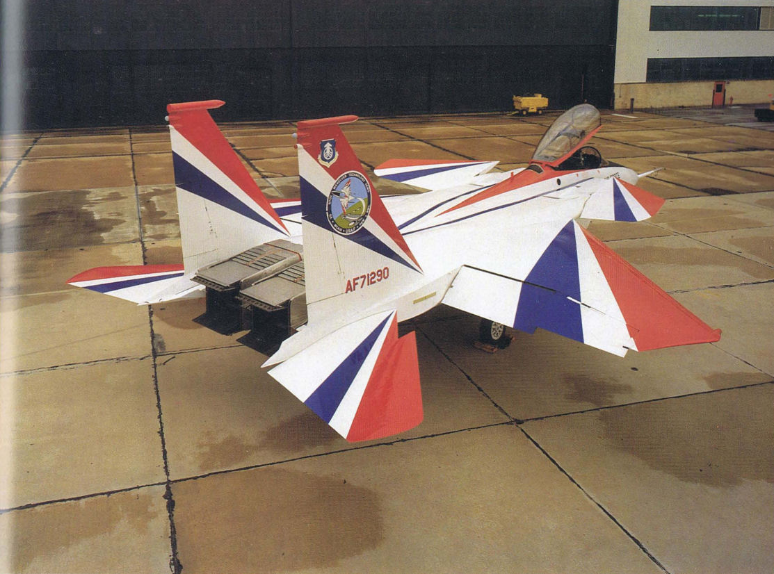
There was no missing the patriotic paint scheme of the F-15 STOL/MTD testbed aircraft.
Самолёты на фотографии: McDonnell Douglas F-15B/D Eagle - США - 1972
-

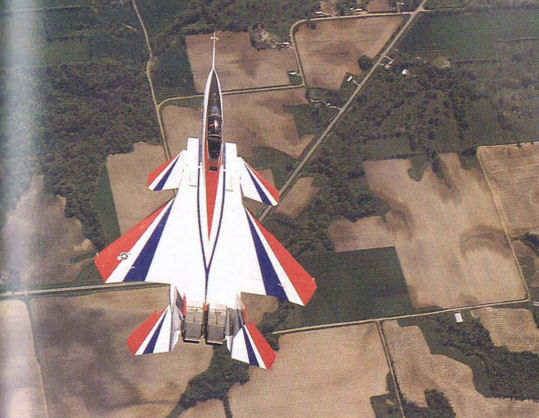
Самолет Agile Eagle предназначался для действий с ВПП длиной не более 305 м в сложных метеоусловиях с использованием ПГО, сопел с изменением вектора тяги и реверсом.
Detail of the aircraft's unique maneuverable propulsion system is visible in this overhead view.Самолёты на фотографии: McDonnell Douglas F-15B/D Eagle - США - 1972
-

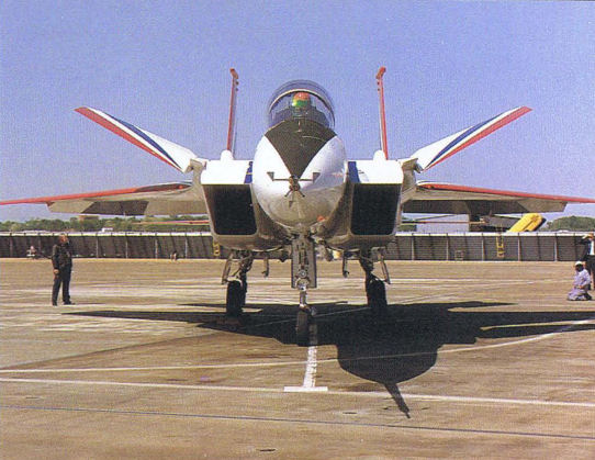
This head-on view of the F-15 STOL/MTD provides a great view of the engine-mounted front canards which provide greater maneuverability capability for the aircraft.
Самолёты на фотографии: McDonnell Douglas F-15B/D Eagle - США - 1972
-

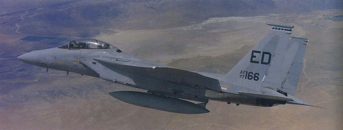
The same 77-166 F-15B was modified from the IFFC configuration to the ABICS configuration. The IFFC tail identification was removed and replaced with the original Edwards tail marking.
Самолёты на фотографии: McDonnell Douglas F-15B/D Eagle - США - 1972
-

The two-dimensional nozzles in full-open position.
Самолёты на фотографии: McDonnell Douglas F-15B/D Eagle - США - 1972
-

An artist's concept from early in the program showing how all operational F-15 STOL/MTD might look.
Самолёты на фотографии: McDonnell Douglas F-15B/D Eagle - США - 1972
-

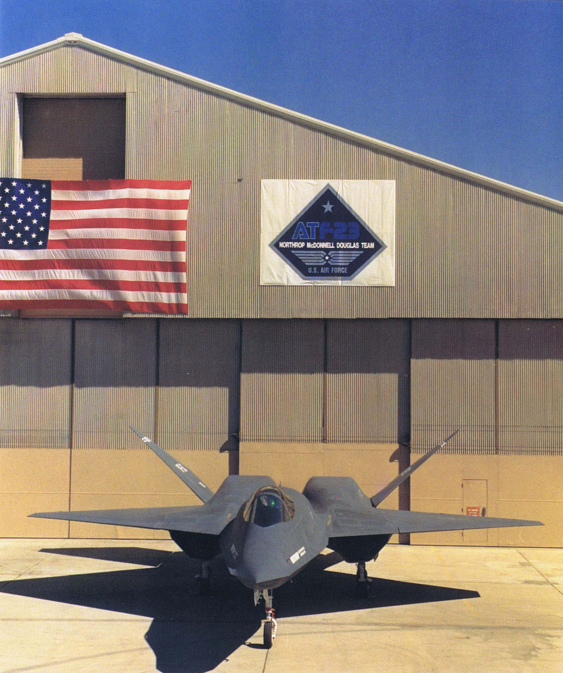
A strange new aircraft to serve as a testbed aircraft is one of the YF-23 prototype fighters which will be used in loads testing. It's shown here in its roll-out.
Самолёты на фотографии: Northrop YF-23 - США - 1990
-

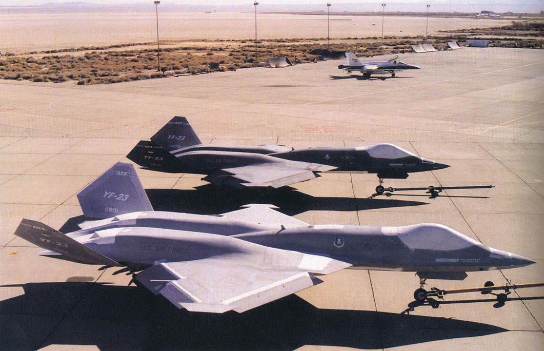
This photo shows the pair of YF-23 prototypes just after they were removed from storage. One of the craft would eventually be used to study strain gauge loads calibration techniques. The other, for the time being, will remain in storage.
Самолёты на фотографии: Northrop YF-23 - США - 1990
-

A T-37, such as the one shown here, served as a prototype for several different attack versions of this aircraft.
Самолёты на фотографии: Cessna T-37 Tweety Bird - США - 1954
-

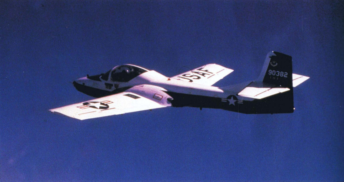
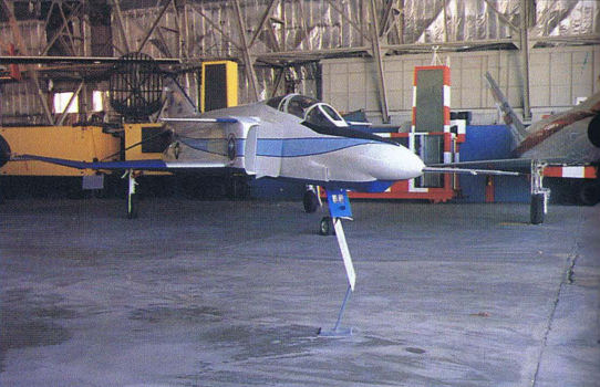
Экспериментальный самолет F-4CCV
This F-4 testbed aircraft started life as the YRF-4 prototype before being converted into a number of other flight control test configurations.Самолёты на фотографии: McDonnell Douglas RF-4 Phantom II - США - 1964
-

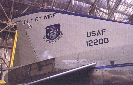
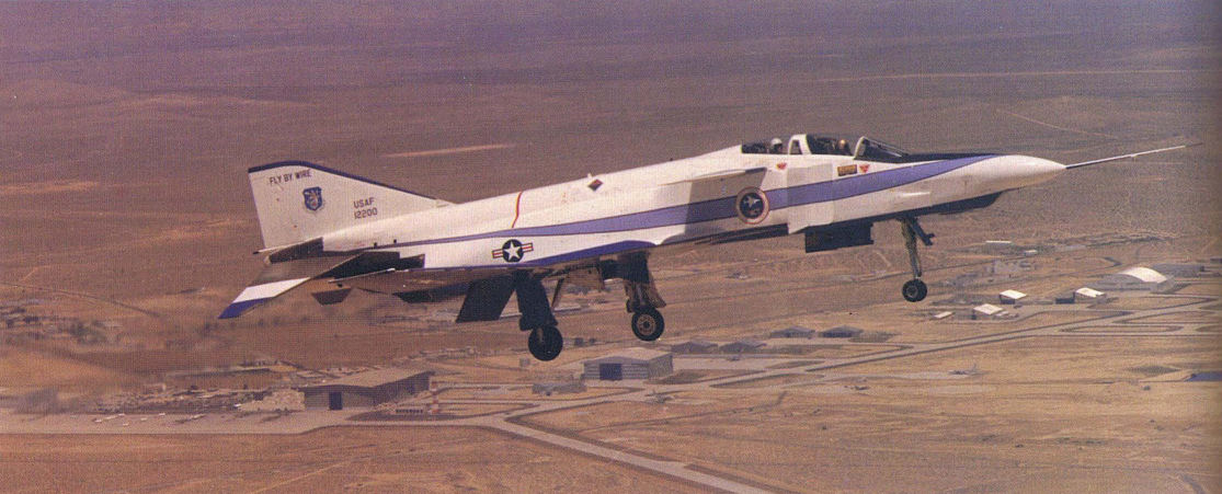
The venerable testbed carried the "Fly-By-Wire" nomenclature throughout its many programs.
Самолёты на фотографии: McDonnell Douglas RF-4 Phantom II - США - 1964
-

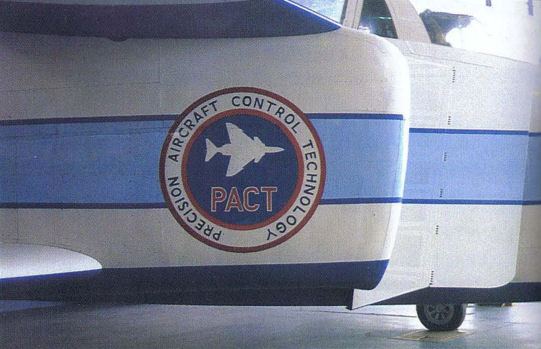
The PACT (Precision Aircraft Control Technology) Program was directed toward improvement in combat maneuvers in future fighter aircraft.
Самолёты на фотографии: McDonnell Douglas RF-4 Phantom II - США - 1964
-

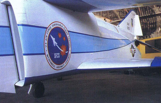
The Survivable Flight Control System (SFCS) modification to the F-4 testbed addressed the development of fly-by-wire technology. The testbed was characterized by flashy full fuselage-length "racing stripes."
Самолёты на фотографии: McDonnell Douglas RF-4 Phantom II - США - 1964
-

The venerable testbed, possibly the most-modified testbed ever, now resides in a position of honor at the Air Force Museum. It's certainly deserved.
Самолёты на фотографии: McDonnell Douglas RF-4 Phantom II - США - 1964
-

The Fly-By-Wire F-4 testbed flairs out on a final approach at Edwards Air Force Base, California.
Самолёты на фотографии: McDonnell Douglas RF-4 Phantom II - США - 1964
-

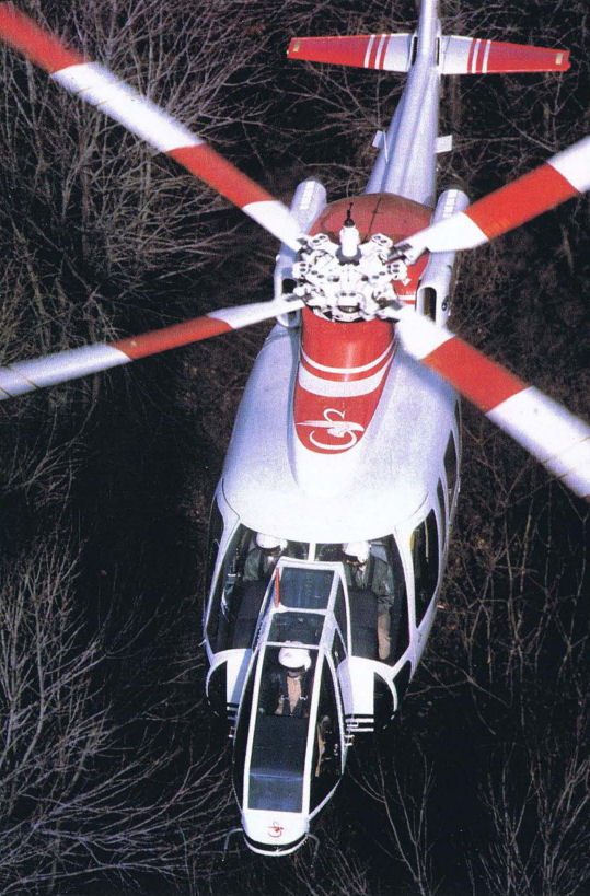
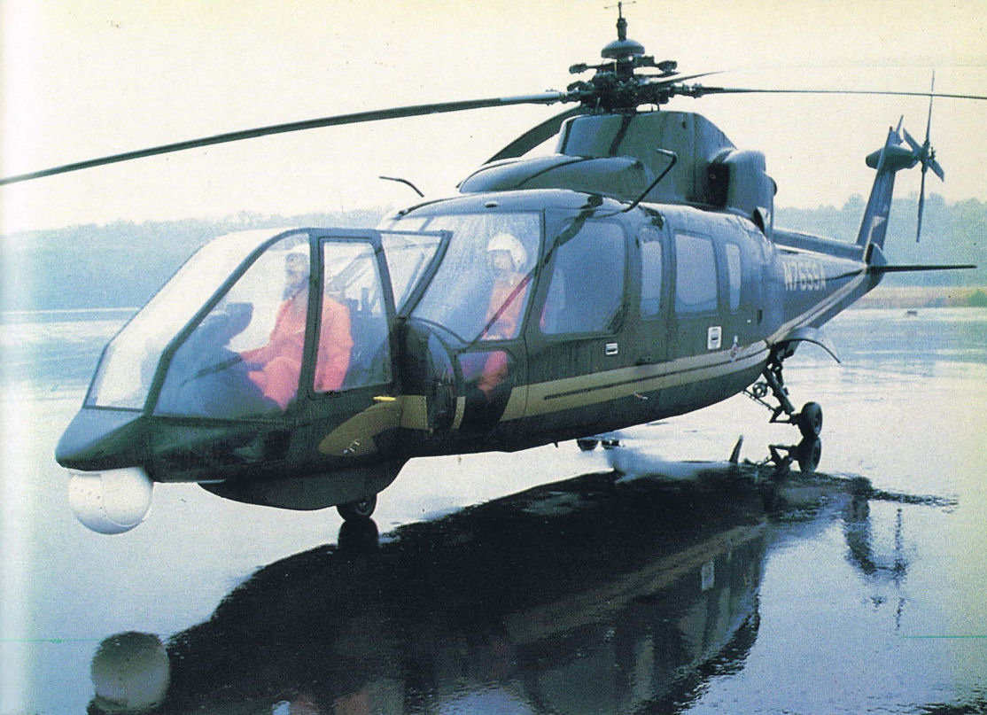
The Shadow in-flight simulator is shown in a typical low-altitude mission profile.
Самолёты на фотографии: Sikorsky S-76 Spirit - США - 1977
-

The extra cockpit allows the Shadow in-flight simulator to study single-cockpit helicopter operations.
Самолёты на фотографии: Sikorsky S-76 Spirit - США - 1977
-

The Shadow evaluation cockpit features dual CRT displays and experimental control sticks.
Самолёты на фотографии: Sikorsky S-76 Spirit - США - 1977
-

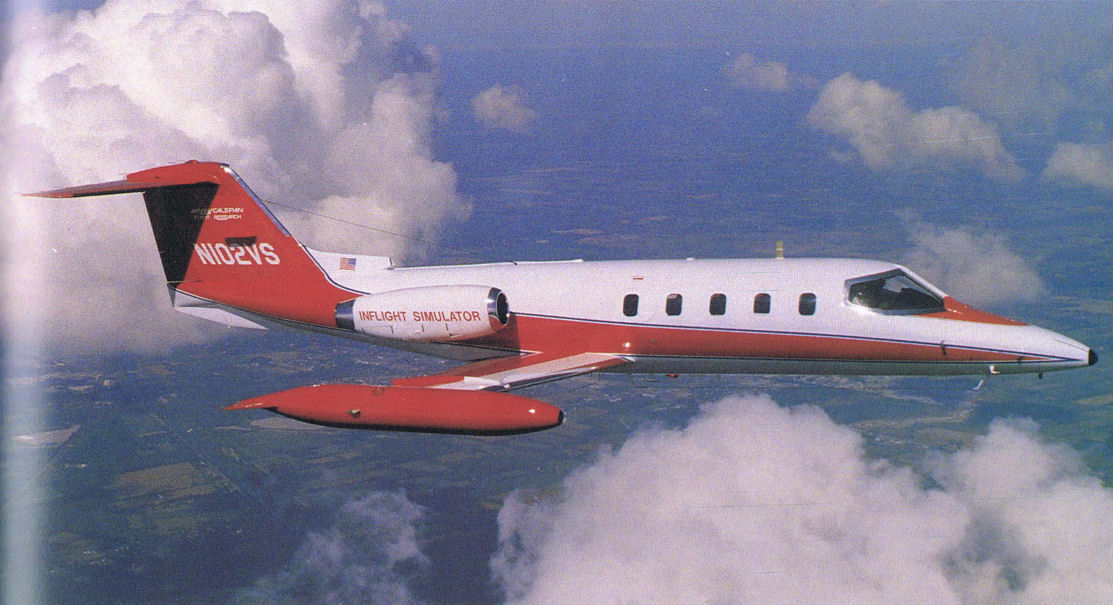
Регистрационный номер: N102VS Calspan Learjet number two is easily distinguished by its additional two windows.
Самолёты на фотографии: Learjet Learjet 23 / 24 / 25 - США - 1963
-

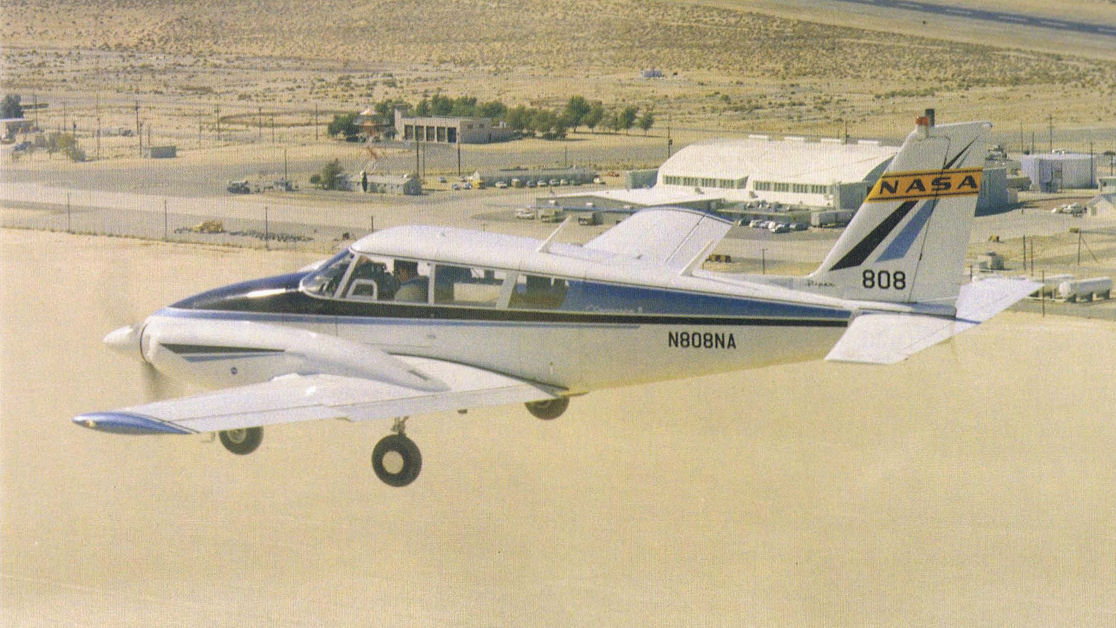
Регистрационный номер: N808NA The PA-30 Twin Commanche served since the 1960s as a general support testbed.
Самолёты на фотографии: Piper Twin Comanche PA-30 - США - 1962
-

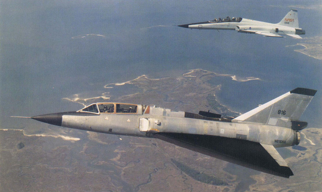
The long-standing NASA F-106 testbed on a test flight. Note the black appendage on the top of the rear fuselage performing some unknown test function. Also note the lack of military markings and the civilian registration number on the aft fuselage of this NASA testbed aircraft.
Самолёты на фотографии: Convair F-106 Delta Dart - США - 1956
-

This busy USAF F-106 testbed was involved in many programs, including an early Integrated Fire Flight Control (IFFC) program, and the fitting of a M61-A1 Gatling Gun on the bottom of the fuselage.
Самолёты на фотографии: Convair F-106 Delta Dart - США - 1956
-

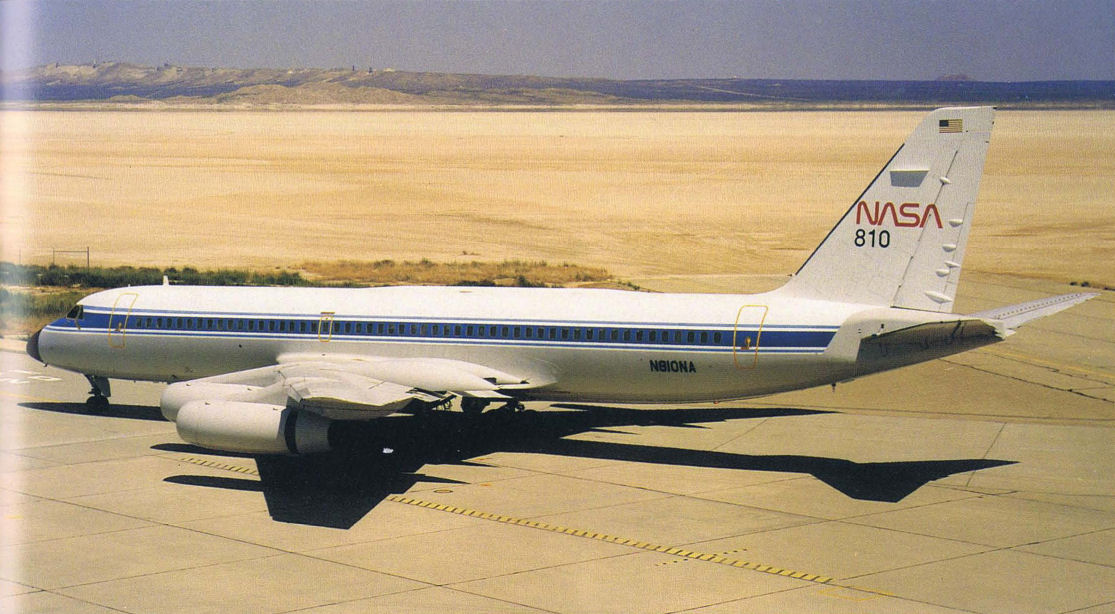
Регистрационный номер: N810NA The LSRA Convair 990 taxis from the NASA Dryden facility. Note the taxiway behind the vertical tail and the rocket engine lest rigs located on the mountain.
Самолёты на фотографии: Convair CV-880 / CV-990 Coronado - США - 1959
-

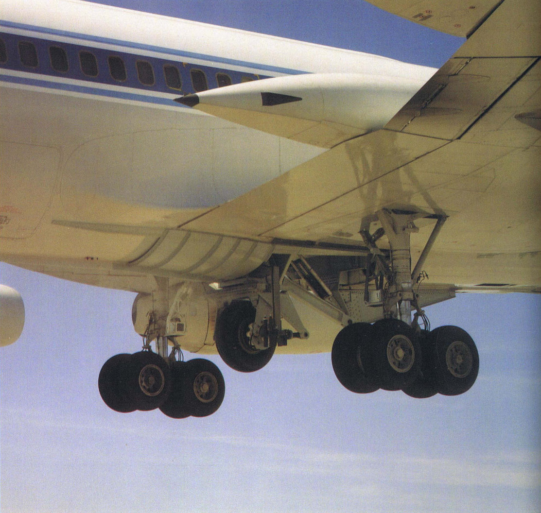
A close-up view of the LSRA shuttle landing gear installation.
Самолёты на фотографии: Convair CV-880 / CV-990 Coronado - США - 1959
-

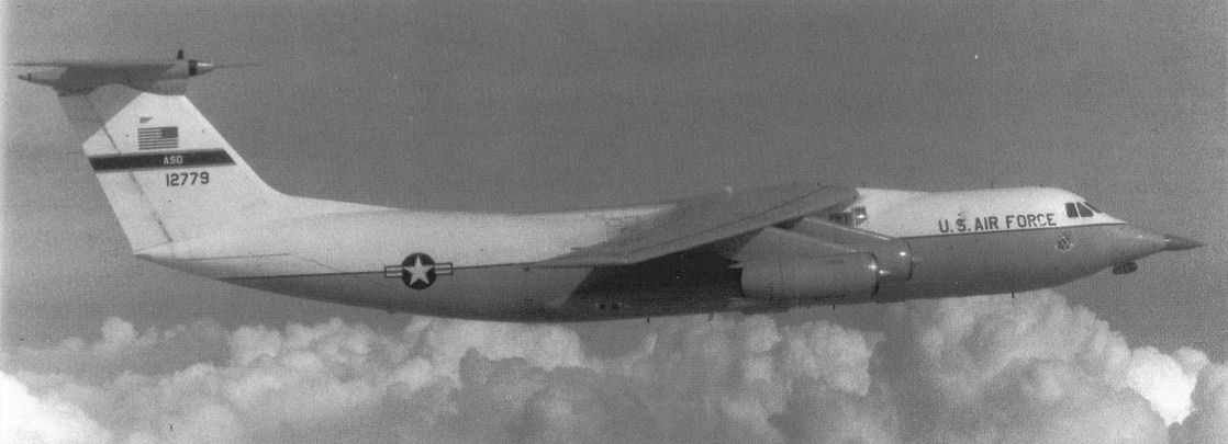
This early model C-141 transport was modified for the Advanced Radar Test Bed (ARTB) and could be fitted with several different noses from current aircraft.
Самолёты на фотографии: Lockheed C-141 Starlifter - США - 1963
-

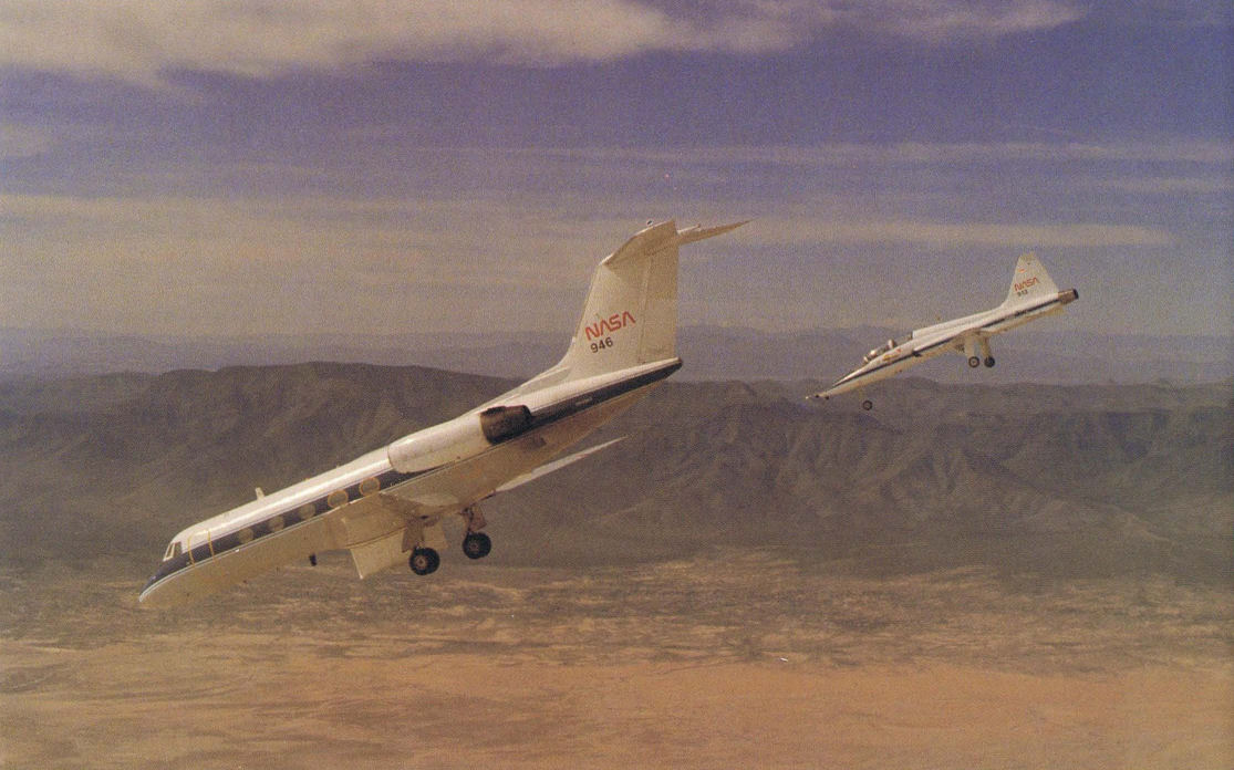
Регистрационный номер: N946NA Shuttle Training Aircraft performing a shuttle-type steep approach. Note the side-force generator located under the fuselage which was eventually removed.
Самолёты на фотографии: Grumman Gulfstream II - США - 1966
-

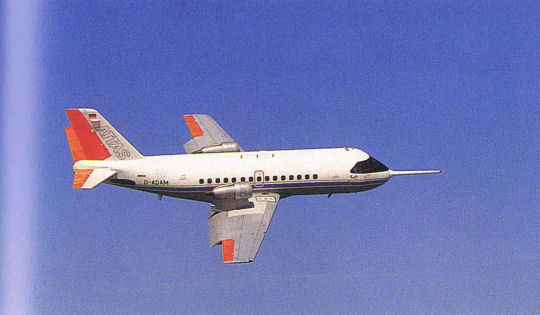
Регистрационный номер: D-ADAM [2] ATTAS in-flight simulator with flaps extended in order to produce direct lift.
Самолёты на фотографии: VFW-Fokker VFW 614 - Германия - 1971
-

Регистрационный номер: D-ADAM [2] The ATTAS in-flight simulator was built from a VFW-614 twin-jet transport.
Самолёты на фотографии: VFW-Fokker VFW 614 - Германия - 1971
-

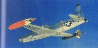
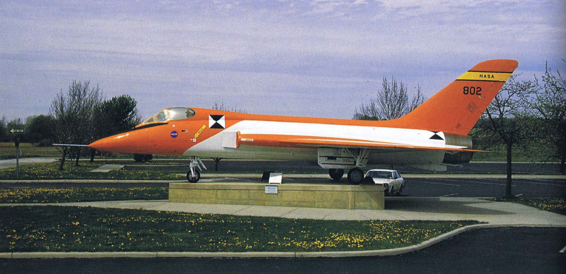
This particular F-5D, which was flown by Neil Armstrong, and is now on display in front of the Neil Armstrong Museum at Wapakoneta, Ohio, just north of Dayton.
Самолёты на фотографии: Douglas F5D Skylancer - США - 1956
-

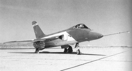
This is one of two F5D-1 Skylancers modified by NASA for research operations. The aircraft was involved with simulations of DynaSoar landings.
Самолёты на фотографии: Douglas F5D Skylancer - США - 1956
-
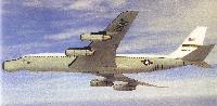
This photo shows the EC-18B ARIA configuration. The ARIA concept was developed in 1968.
Самолёты на фотографии: Boeing EC-135E / EC-18 ARIA / Condor - США - 1968
-
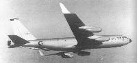
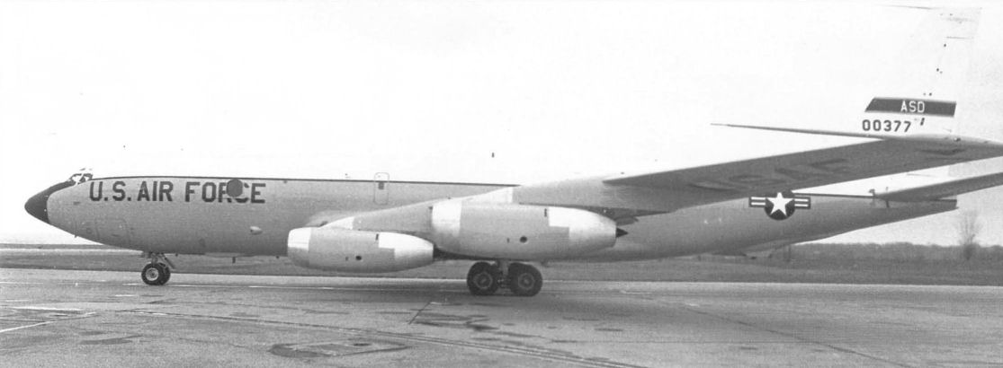
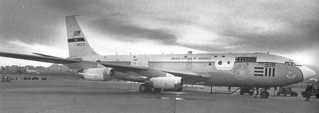
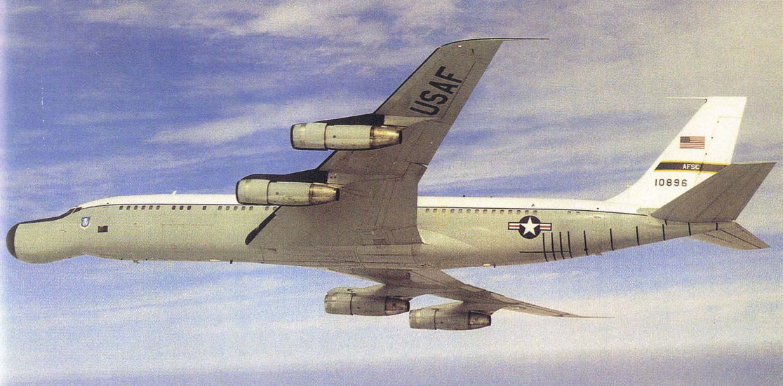
The ARIA modification is the most recognizable testbed aircraft in the world. A number of Boeing 707s and KC-135s have been modified into EC-18s and EC-135s. This particular version is an EC-18 aircraft.
Самолёты на фотографии: Boeing EC-135E / EC-18 ARIA / Condor - США - 1968
-

This Cessna 402B testbed has performed a number of different test missions. It has been at NASA Langley since 1982.
Самолёты на фотографии: Cessna 411/401/402/421/414/404 - США - 1962
-

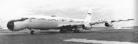
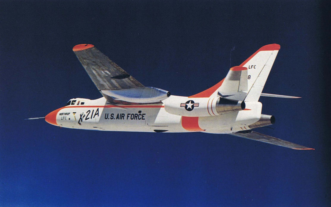
The X-21A was the only "X" aircraft that wasn't built from scratch. Two of them were built from a pair of B-66 bombers.
Самолёты на фотографии: Northrop X-21 - США - 1963
-

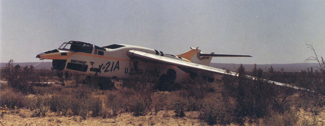
Not all testbeds end up gloriously. One of the X-21A testbeds ended up deserted on the desert.
Самолёты на фотографии: Northrop X-21 - США - 1963
-

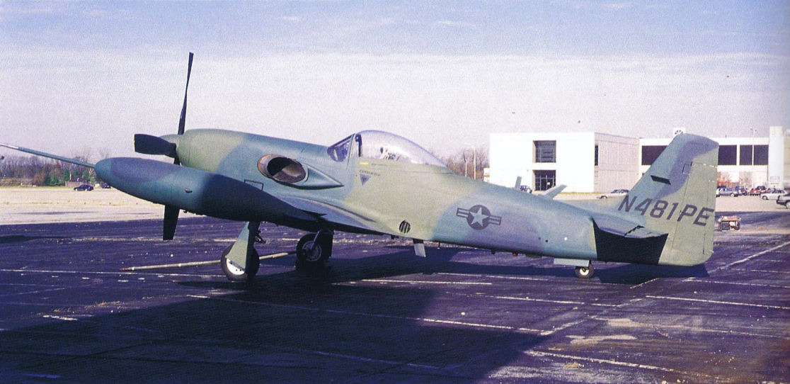
Регистрационный номер: N481PE [2] It might look a lot like a World War II P-51 fighter, but this testbed aircraft was developed from the old fighter for modern counterinsurgency missions.
Самолёты на фотографии: Piper Enforcer PA-48 - США - 1971
-

Регистрационный номер: N481PE [2] The major difference in the "old and new" Mustang was the powerplant, which was changed to a turboprop for the Mustang Enforcer version.
Самолёты на фотографии: Piper Enforcer PA-48 - США - 1971
-

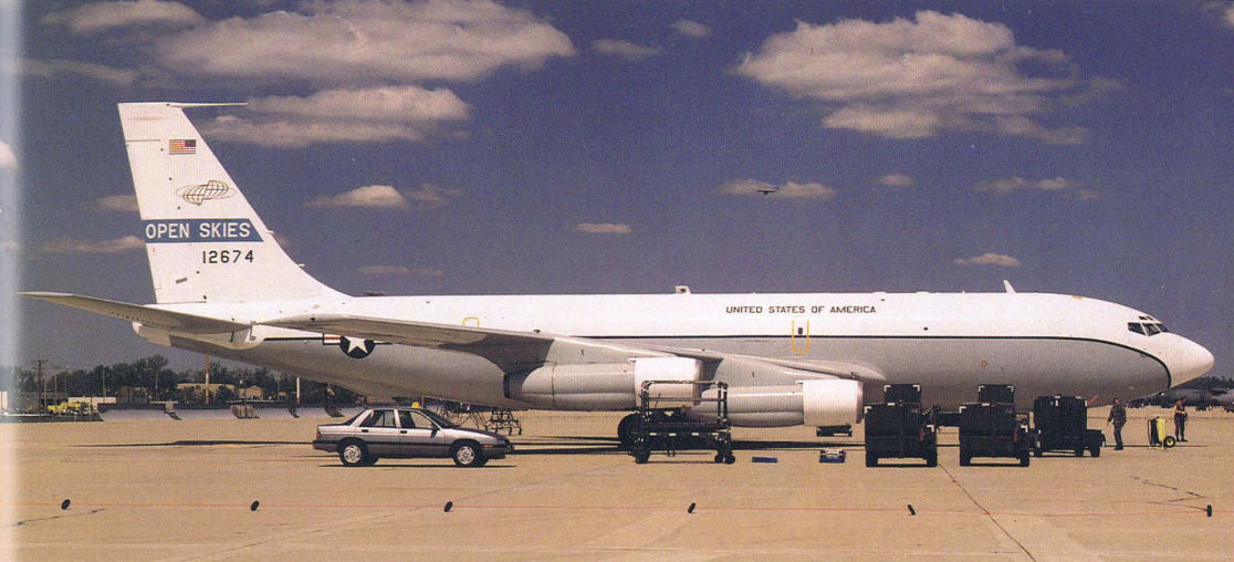
The OPEN SKIES C-135 testbed aircraft is the newest version of the model for the 1990s time period. The mission of this sophisticated aircraft was to provide aerial observation to support an international treaty.
Самолёты на фотографии: Boeing RC-135 - США - 1964
-

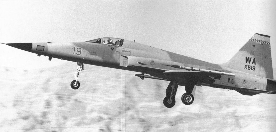
This F-5E testbed aircraft tested a composite material landing gear strut in 1987. This particular F-5E was a member of the USAF Aggressor Squadron, another example ofa test being accomplished as a part of the normal operational mission.
Самолёты на фотографии: Northrop F-5E Tiger II - США - 1972
-

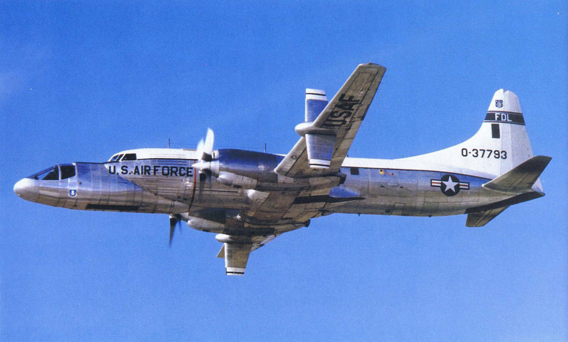
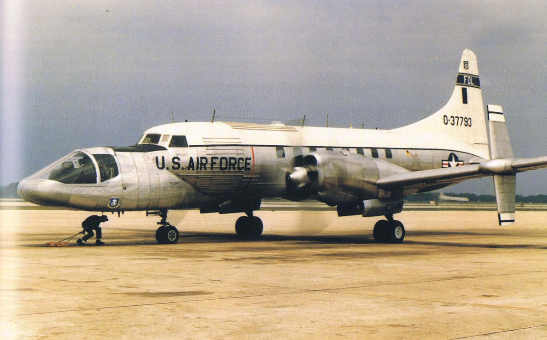
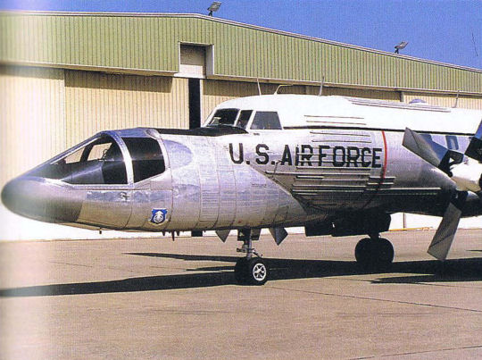
The C-131H TIFS in-flight simulator is one of the most recognizable of the production-turned-research aircraft. The C-131 is highly instrumented and carries a low-mounted front nose.
Самолёты на фотографии: Convair CV-540/CV-580/CV-600/CV-640 - США - 1955
-
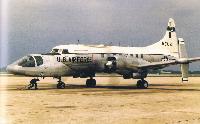
TIFS aircraft on the ground at Kelly Air Force Base in 1985.
Самолёты на фотографии: Convair CV-540/CV-580/CV-600/CV-640 - США - 1955
-
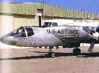
The TIFS' simulation nose certainly makes this a unique one-of-a-kind aircraft.
Самолёты на фотографии: Convair CV-540/CV-580/CV-600/CV-640 - США - 1955
-
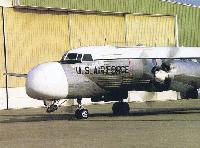
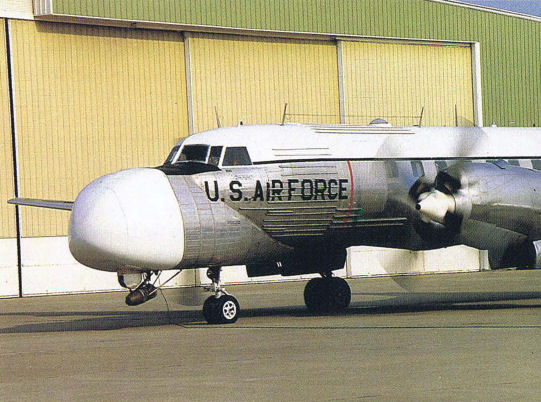
With radome installed, TIFS is used to teach avionics testing.
Самолёты на фотографии: Convair CV-540/CV-580/CV-600/CV-640 - США - 1955
-

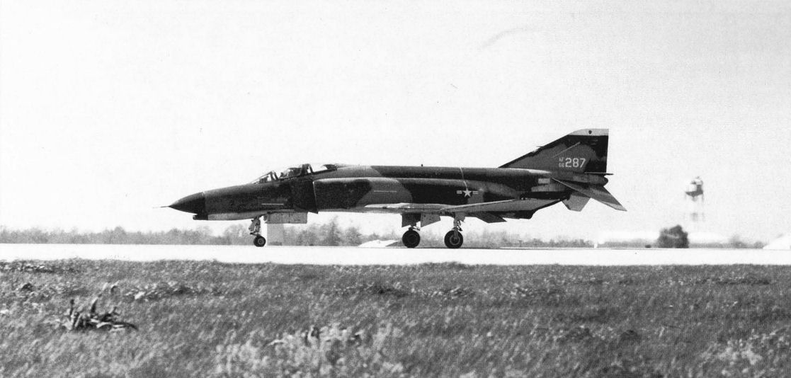
A highly-instrumented F-4 testbed was tested to determine how much surface roughness the plane could operate from. The program was called "Have Bounce."
Самолёты на фотографии: McDonnell Douglas F-4E / F-4F Phantom II - США - 1965
-

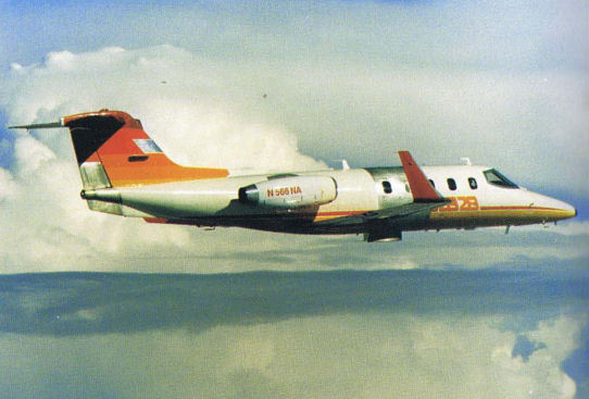
Регистрационный номер: N566NA [2] This Learjet performed laminar flow experiments. There are several portions of unpainted skin sections, not an unusual appearance on testbed aircraft.
Самолёты на фотографии: Learjet Learjet 28 / 29 Longhorn - США - 1977


Статьи
- S.Markman & B.Holder - One-of-a-kind research aircraft