
Варианты
- Burnelli - UB-14 - 1934 - США
- Cunliffe-Owen - OA-1 Clyde Clipper - 1939 - Великобритания
Burnelli (самолеты В. Бурнелли)
<...>
Бурнелли построил затем улучшенный UB-14B, один из таких самолетов был построен в 1938 году британской компанией "Cunliffe Owen Aircraft" - это был усовершенствованный вариант Cunliffe Owen OA-1, построенный в единственном экземпляре и оснащенный двумя звездообразными моторами Bristol Perseus XIVC мощностью по 710 л. с.
<...>
Описание:
- Burnelli (самолеты В. Бурнелли)
- Flight, December 1938
UNORTHODOX TRANSPORT - Flight, November 1939
Britain's Civil Aircraft
Фотографии

-

Aeroplane Monthly 1985-10 / A.Lumsden, T.Heffernan - Probe Probare (17)
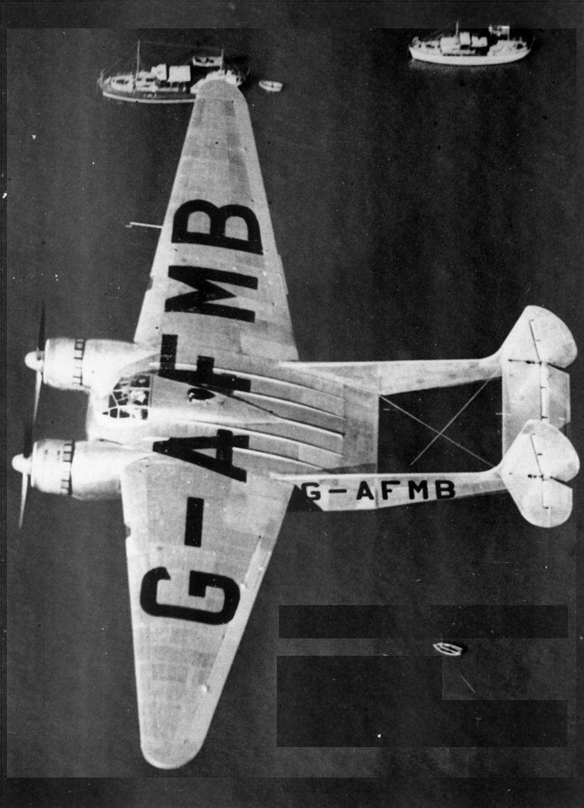
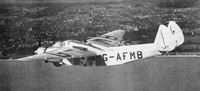
Регистрационный номер: G-AFMB [22] The Cunliffe-Owen OA-1 s lifting fuselage is shown well in this air-to-air photograph taken near Southampton shortly before the war.
-

Aeroplane Monthly 1984-04 / Personal album
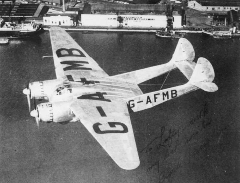
Регистрационный номер: G-AFMB [22] This air-to-air photograph taken over the OA-1's birthplace bears a personal inscription to Mr Smith - “To Lofty with best wishes - Clyde Pangborn”.
-
Aeroplane Monthly 1984-04 / Personal album
Регистрационный номер: G-AFMB [22] Another air-to-air study of G-AFMB flying in the vicinity of Southampton.
The OA-1 was the sole example built by Cunliffe-Owen Aircraft. In 1941 the aircraft was impressed into RAF service and in June was delivered by Jim Mollison to the Free French Air Force. It was eventually burned on VJ night at El Kabrit on a celebration bonfire. -
Aeroplane Monthly 1980-06 / R.Riding - Burnelli's Lifting Fuselages (4)
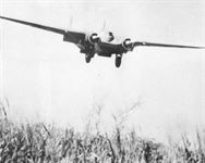
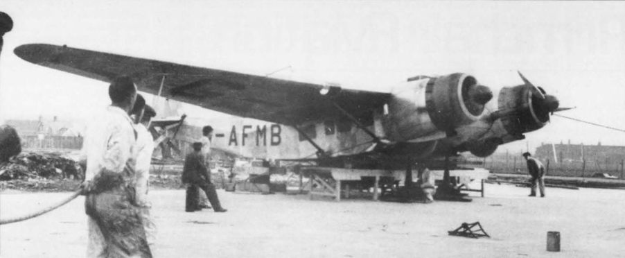
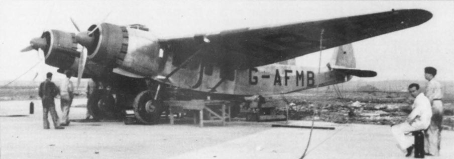
Регистрационный номер: G-AFMB [22] The camouflaged OA-1, still in its civil marks, landing in French Equatorial Africa in June 1941.
-

Aeroplane Monthly 1985-10 / A.Lumsden, T.Heffernan - Probe Probare (17)
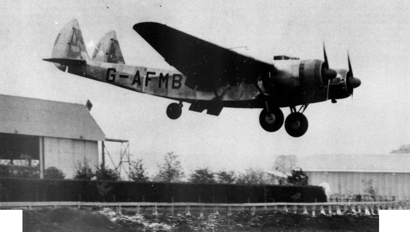
Регистрационный номер: G-AFMB [22] The Cunliffe-Owen OA-1 landing at Eastleigh after a test flight on May 4, 1939. Note the under-fuselage flap.
-
Aeroplane Monthly 1980-06 / R.Riding - Burnelli's Lifting Fuselages (4)
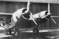
Регистрационный номер: G-AFMB [22] The OA-1 shortly after roll-out, in bare metal finish before painting. It made its first flight, from Eastleigh, on January 12, 1939.
-

Air-Britain Archive 1980-03
Регистрационный номер: G-AFMB [22] Cunliffe-Owen O.A.1 (UK) Improved version of the Burnelli UB-14 airliner, built during 1937-38 and powered by two Bristol Perseus XIV engines. One operated by the French in Africa.
The last of the entries in this instalment is British Burnelli Flying Wing G-AFMB. Based on the American-designed UB.14 it was built at Eastleigh and delivered to the FreeFrench in 1941. -
Aeroplane Monthly 1984-04 / Personal album
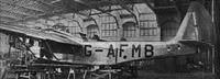
Регистрационный номер: G-AFMB [22] The completed OA-1 during engine runs at Eastleigh in the winter of 1938.
-

Aeroplane Monthly 1984-04 / Personal album
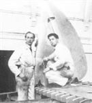
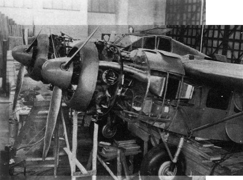
Регистрационный номер: G-AFMB [22] A close-up view of the centre section
-

Aeroplane Monthly 1989-11 / Personal album. Military
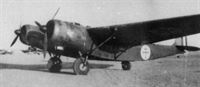
Регистрационный номер: G-AFMB [22] The futuristic British Burnelli OA-1, built by the Cunliffe Owen Aircraft company in 1938, seen at Luqa, Malta in July 1941. Camouflaged and carrying wartime civil markings, it was en route to the Free French Air Force in West Africa, flown by Jim Mollison. Registered G-AFMB, the OA-1 had been impressed into the RAF in May 1941.
-
Aeroplane Monthly 1985-10 / A.Lumsden, T.Heffernan - Probe Probare (17)
Регистрационный номер: G-AFMB [22] The 15-seater OA-1 was powered by two 710 h.p. Bristol Perseus XIVC radial engines.
-

Flight 1939-04 / Flight
Регистрационный номер: G-AFMB [22] Seen here on its first test outing, the Cunliffe-Owen is now flying again on a second series of tests.
-

Aeroplane Monthly 1984-04 / Personal album
Регистрационный номер: G-AFMB [22] The OA-1 undergoing undercarriage retraction tests at Eastleigh, probably when problems arose with the differential braking system, revealed during taxying trials.
-

Aeroplane Monthly 1984-04 / Personal album
Регистрационный номер: G-AFMB [22] The OA-1 undergoing undercarriage retraction tests at Eastleigh, probably when problems arose with the differential braking system, revealed during taxying trials.
-
Flight 1938-12 / Flight
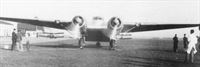
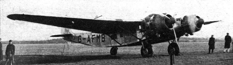
Регистрационный номер: G-AFMB [22] AERODYNAMIC ACCOMMODATION: The first of the new British Burnellis emerges from the Cunliffe-Owen Aircraft shops at Southampton for test flights. Bristol Perseus XIVC sleeve-valve engines, giving 900 h.p. each for take-off, are fitted. Among the new features is the control-cabin superstructure, which gives a good view abeam.
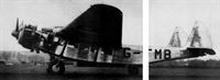
This view, secured on the occasion of the new transport’s first “airing,” gives an idea of the proportions and size. -
Flight 1938-12 / Flight
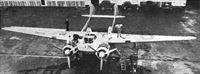
Регистрационный номер: G-AFMB [22] This three-quarter rear view of the new Cunliffe-Owen transport shows the shape of the tail booms.
-
Aeroplane Monthly 1984-04 / Personal album
Регистрационный номер: G-AFMB [22] Working on the fin and rudder assemblies of the OA-1 at Eastleigh.
-

Aeroplane Monthly 1980-06 / R.Riding - Burnelli's Lifting Fuselages (4)
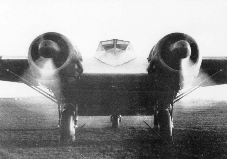
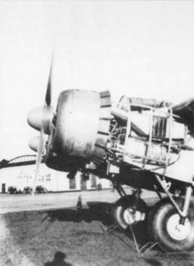
Регистрационный номер: G-AFMB [22] The nacelles of the Bristol Perseus XIVC sleeve-valve engines are located at the front corners of the central wing portion or fuselage.
-

Aeroplane Monthly 1984-04 / Personal album
Регистрационный номер: G-AFMB [22] Running the two Perseus engines at Eastleigh in the winter of 1938.
-
Aeroplane Monthly 1980-12 / Skywriters
Регистрационный номер: G-AFMB [22] A photograph of the Burnelli Cunliffe-Owen Clyde Clipper in free French markings. The picture was taken in North Africa during the war when the aeroplane served as General de Gaulle’s personal transport.
-

Aeroplane Monthly 1985-10 / A.Lumsden, T.Heffernan - Probe Probare (17)
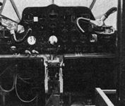
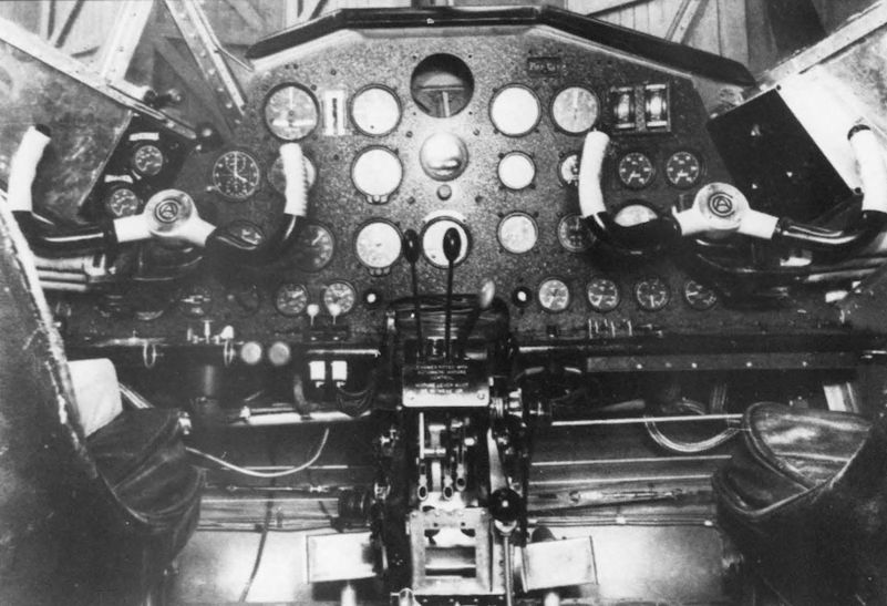
Регистрационный номер: G-AFMB [22] The layout of the OA-1's flying controls was considered good; the absence of a floor-mounted control column added to the pilot's comfort, although the control wheel rose unnaturally high when pulled fully aft.
-
Flight 1938-12 / Flight
Регистрационный номер: G-AFMB [22] The cockpit (in a not-quite completed state), showing the way in which the controls are taken from the sides instead of the floor.
-
-

-
-

-

-

-

-

-

-

-

-
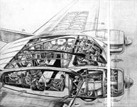
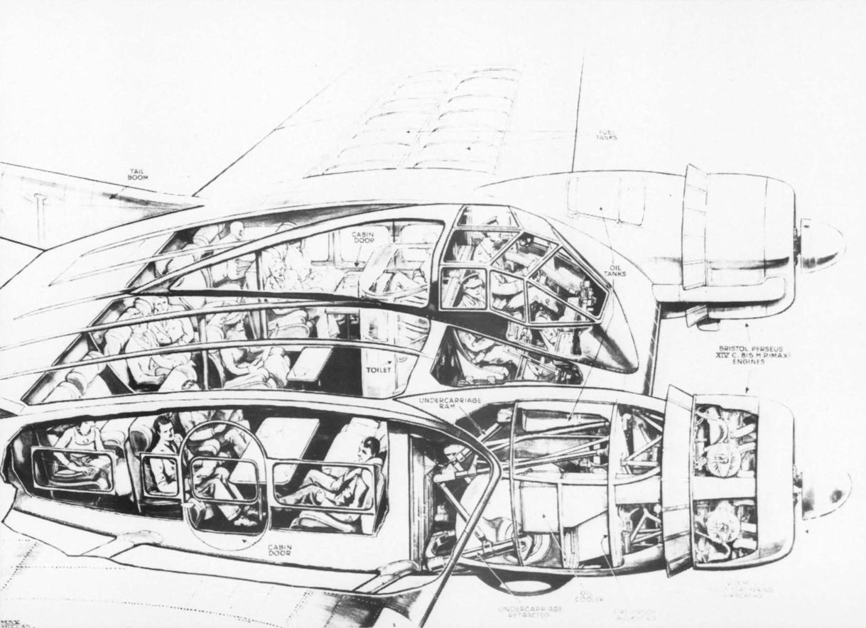
Flight 1938-12 / Flight
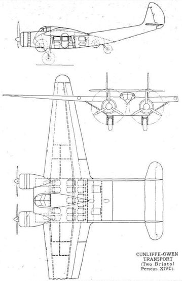
The general layout and accommodation of the new Cunliffe-Owen may be visualised from this specially prepared Flight drawing. The installation of the Bristol Perseus sleeve-valve engines is also evident.
-

-

-
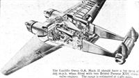
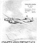
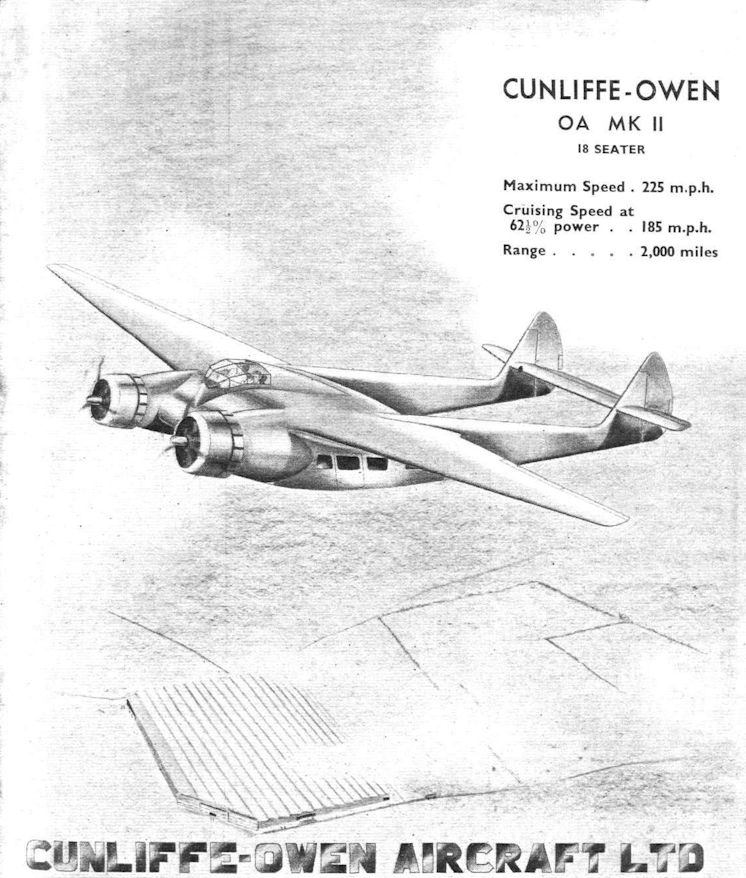
Flight 1939-11 / Flight
The Cunliffe Owen O.A. Mark II should have a top speed of 225 m.p.h. when fitted with two Bristol Perseus XIVC sleeve-valve engines. The range is estimated at 1,985 miles.
-
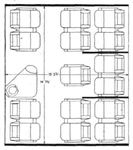
Flight 1939-04 / Flight
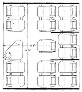
Roominess is the main feature of the Cunliffe-Owen cabin.
-

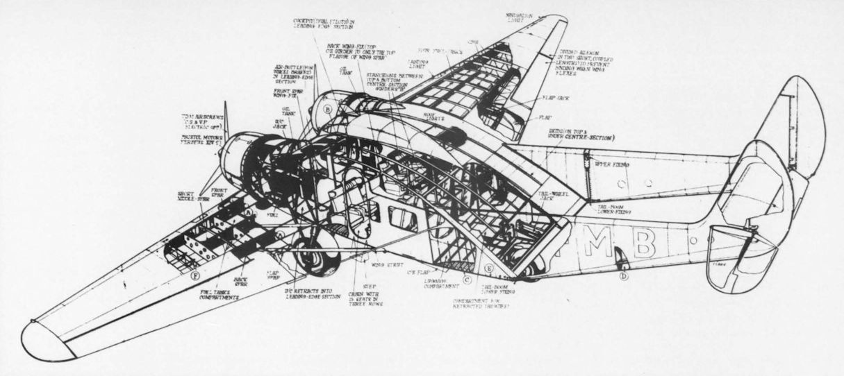
Flight 1938-12 / Flight
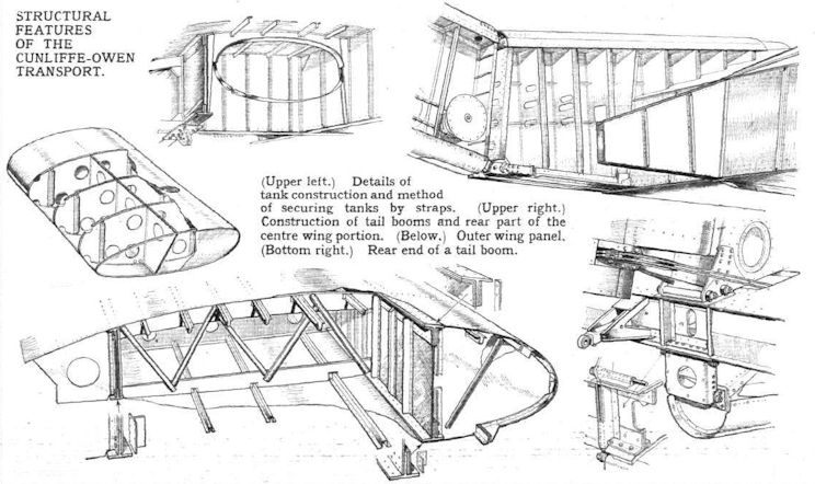
STRUCTURAL FEATURES OF THE CUNLIFFE-OWEN TRANSPORT.
-

Flight 1938-12 / Flight
CUNLIFFE-OWEN TRANSPORT (Two Bristol Perseus XIVC)


- Фотографии