
Parnall. Самолеты
<...>
Единственный экземпляр двухместного спортивного биплана Imp с двигателем Armstrong Siddeley Genet II мощностью 80 л. с. был сертифицирован в мае 1928 года. Позже самолет Imp использовался для летных испытаний звездообразного двигателя Pobjoy P мощностью 65 л. с., в декабре 1933 года он был списан.
<...>
Описание:
- Parnall. Самолеты
- Flight, April 1928
THE PARNALL "IMP” - Flight, July 1928
THE PARNALL "IMP”
Фотографии

-
Flight 1928-07 / Flight
Регистрационный номер: G-EBTE [17] -
Flight 1928-04 / Flight
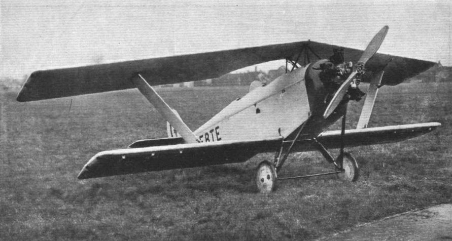
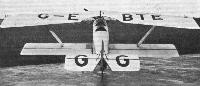
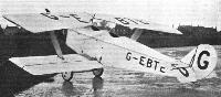
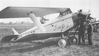
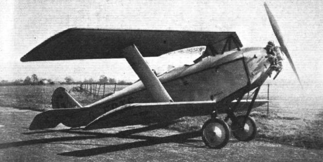
Регистрационный номер: G-EBTE [17] THE PARNALL "IMP": Rear view. The raked inter-plane struts transmit the lift from the top plane to the lower, cantilever, wing. Ailerons run the whole span of the bottom plane.
-
Flight 1928-04 / Flight
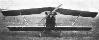
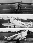
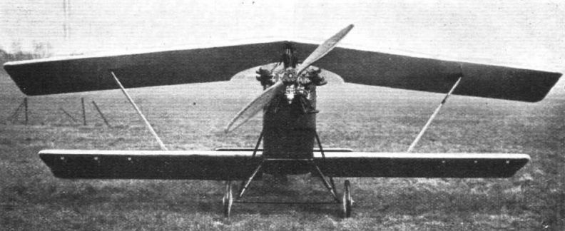
Регистрационный номер: G-EBTE [17] THE PARNALL "IMP": Front view. The engine is an Armstrong-Siddeley "Genet." By removing the top plane, cabane and struts, the machine can be converted into a low-wing, cantilever monoplane.
-
Flight 1928-04 / Flight
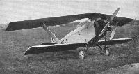
Регистрационный номер: G-EBTE [17] THE PARNALL "IMP": Three-Quarter rear view. Note that both cockpits are clear of the top trailing edge, and that thus the view is very good.
-
Aeroplane Monthly 1981-11 / K.Wixey - Parnall Imp /British pre-war ultralights/
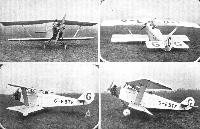
Регистрационный номер: G-EBTE [17] Three views of the Imp in its original state, with 80 h.p. Armstrong Siddeley Genet II, later exchanged for the 65 h.p. Pobjoy “P” engine.
-
Flight 1928-03 / Flight
Регистрационный номер: G-EBTE [17] A NEW LIGHT AEROPLANE: The Parnall "Imp" with Armstrong-Siddeley "Genet" engine is of somewhat unorthodox design. The top plane has a pronounced sweep-back, and the wings are cantilevers. The wing arrangement was evidently chosen so as to give a good view from both cockpits.
-
Air Enthusiast 2003-01 / K.Wixey - The Bolas touch
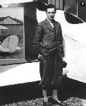
Регистрационный номер: G-EBTE [17] Two-seat civil sporting biplane initially powered by an 80hp (59kW) Annstrong Siddeley Genet II five-cylinder radial, and later a 65hp (48kW) Pobjoy P seven-cylinder radial. Illustrated is Bolas beside the only example, G-EBTE, in 1927. Here powered by an 80hp (59kW) Armstrong Siddeley Genet II air-cooled radial. The upper wings featured a pronounced sweepback but the lower wings were straight.
-
Flight 1928-05 / Flight
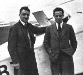
Регистрационный номер: G-EBTE [17] TWO "IMPS": On the right is Mr. Bolas, designer of the Parnall "Imp" which won the Balloon Bursting Competition. With him is Flt.-Lieut. Bonham Carter, who flew it.
-
Aeroplane Monthly 1988-07 / Personal album. Civil
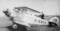
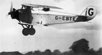
Регистрационный номер: G-EBTE [17] The sole Parnall Imp, G-EBTE, an attractive two-seat cantilever biplane powered by a 80 h.p. Genet II engine. First flown in 1927, at Yate, the Imp was raced into eighth place in the 1928 King’s Cup race, flown by Flt Lt D. W. Bonham Carter - note the faired-in front cockpit. The Imp was scrapped in December 1933.
-
Aeroplane Monthly 1981-11 / K.Wixey - Parnall Imp /British pre-war ultralights/
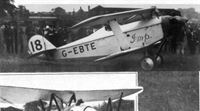
Регистрационный номер: G-EBTE [17] SOME MORE COMPETING MACHINES: The Parnall "Imp" (Siddeley "Genet II") with Flying-Officer W. Bonham-Carter up. The Parnall "Imp" is unusual in having its top plane arranged with a pronounced sweep-back.
With front seat faired over and the Genet engine streamlined, the Imp takes off from Hendon during the 1928 King's Cup Air Race in July. -
Aeroplane Monthly 1982-11 / P.Capon - Capon's Corner
Регистрационный номер: G-EBTE [17] Taking part in the 1928 King's Cup race was the Parnall Imp G-EBTE, seen here at Hamble on July 21, 1928. It was flown in the race by Flt Lt D. W, Bonham Carter and placed eighth.
-
Aeroplane Monthly 1981-11 / K.Wixey - Parnall Imp /British pre-war ultralights/
Регистрационный номер: G-EBTE [17] Harold Bolas flying the Imp in March 1928.
-

Flight 1928-04 / Flight
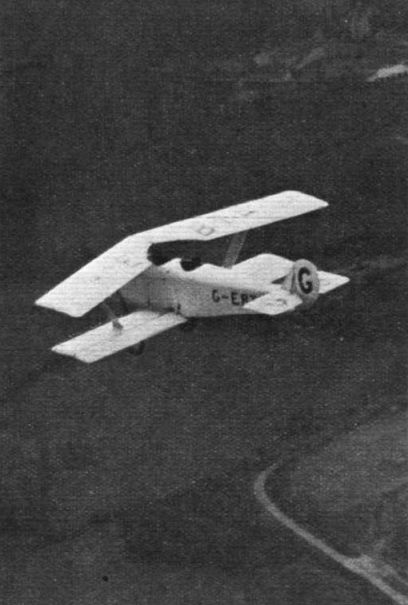
Регистрационный номер: G-EBTE [17] THE PARNALL "IMP" WITH ARMSTRONG-SIDDELEY "GENET" ENGINE: This aerial view, taken from a "Moth" kindly lent by the Wessex Club and piloted by Mr. Bartlett, the Club Instructor, gives a good idea of the unusual arrangement of the wings. On this occasion the "Imp" was piloted by Mr. Harold Bolas, its designer.
-
Flight 1928-05 / Flight
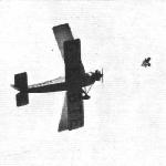
Регистрационный номер: G-EBTE [17] Balloon "Strafing": Flight-Lieut. Bonham Carter well on his target in the Parnall "Genet-Imp." The swept-back top plane of this machine caused an onlooker to describe it as "An 'Autogiro' with one vane seized up."
-

Flight 1929-07 / Flight
Регистрационный номер: G-EBTE [17] The "Pobjoy Imp": A Parnall 2-seater light biplane, equipped with the 60 h.p. Pobjoy engine, with which an air speed of 100 m.p.h. is obtained. Parts of the Pobjoy engine (which has previously been described in "Flight") are being made by A.C. (Acedes) Cars, Ltd.!
-
Flight 1928-05 / Flight
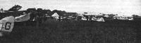
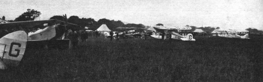
Регистрационный номер: G-EBTE [17] This is a general view of the machines grouped round the enclosures with the Parnall "Imp" in the foreground.
-

Aeroplane Monthly 1988-08 / P.Jarrett - Parnall's pinwheels
Регистрационный номер: G-EBTE [17] J9038 approaches completion in Parnall's experimental works at Yate, Gloucestershire. Parnall Imp G-EBTE can be seen in the background.
Другие самолёты на фотографии: Cierva/Parnall C.10 / C.11 - Великобритания - 1927
-
Flight 1928-04 / Flight
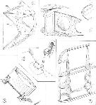
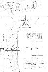
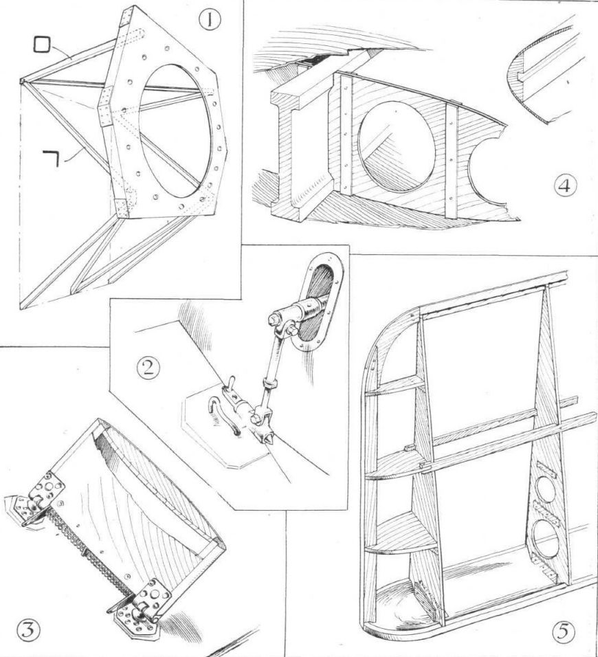
THE PARNALL "IMP" LIGHT AEROPLANE: Some Constructional Details. The engine plate is supported on a system of square tubes and angle sections, as shown in 1. The quick-release attachment of the aileron controls is shown in 2, while 3 illustrates the attachment of the interplane struts to lower plane. The same sketch also shows the general construction of the strut. The wing construction, consisting of false spars or stringers, and ribs or formers, with spruce planking, is indicated in 4, and the aileron and elevator construction in 5.
-
Flight 1928-04 / Flight
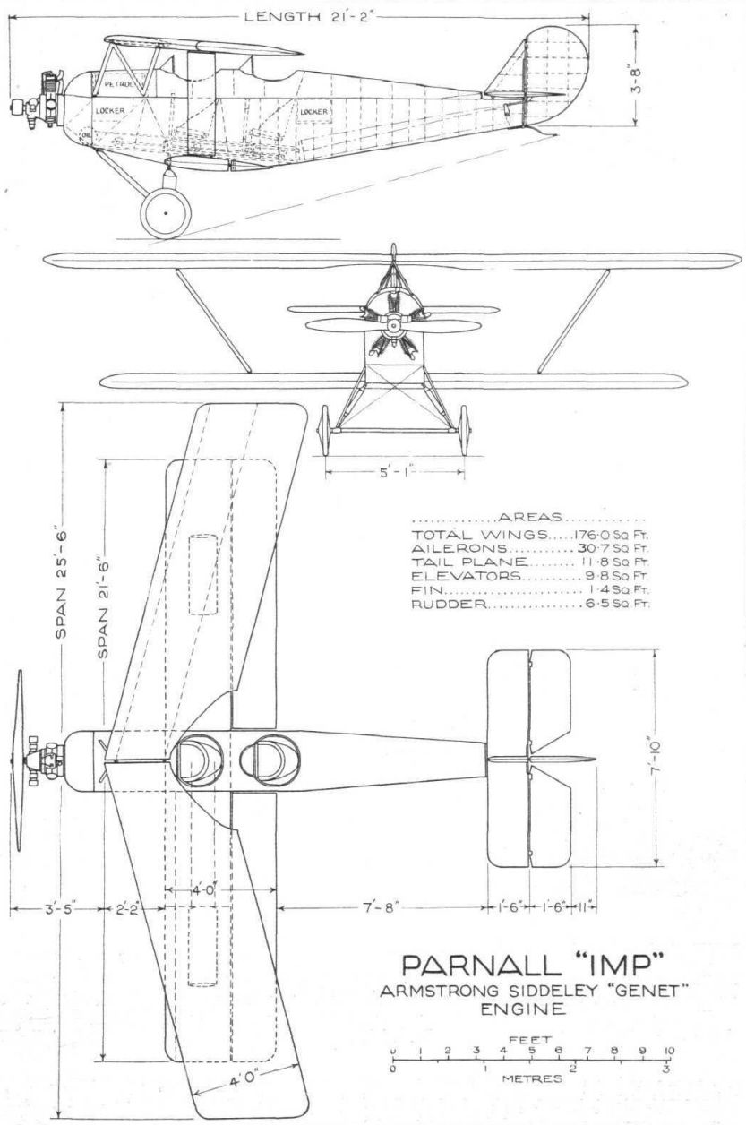
Parnall "Imp" Armstrong Siddeley "Genet" Engine


- Фотографии