
Flight, April 1938
A SUPER MILES
PLANS for a somewhat unorthodox four-engined transport aircraft are well advanced at the Phillips and Powis Reading works. Mr. F. G. Miles, who is largely responsible for the commendable foresight the firm displays, is of the opinion that efforts to put British design ahead of competitors will fail if circumstances are allowed to force us into designing along too orthodox or too unorthdox lines. Accordingly, the design of the X.2, as the new machine is called, although representing a striking advance, does not bring in fresh problems of control and stability. Two years of work on the basic design have produced no reason for modification of the layout.
The following notes are selected from a preliminary specification lately released:
The aerodynamic design of the X.2 is described by Mr. Miles as a logical advancement on existing designs. The following drag analysis for the machine travelling at 250 m.p.h. and an all-up weight of 55,000 lb. has been made: Skin friction drag. 54 per cent.; induced drag, 11 per cent.; drag due to the wake, 21 per cent.; interference drag. 9 per cent.; cooling drag. 5 per cent. This gives an aerodynamic efficiency (defined as the ratio of the skin friction and induced drag to the total drag) of 65 per cent
Fuselage Structure
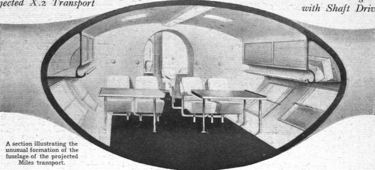
The fuselage, which merges into the wing, is divided by the spars into three main compartments. It is of semi-monocoque construction with former rings and stringers. The design of the centre section spars is worthy of particular note: they virtually form two hoop-shaped bulkheads having same shape as that of the fuselage in their vicinity.
It is claimed that the space available in the X.2 layout is greater than on other aircraft of similar size. The total cabin volume is 3.068 cu. ft., of which 350 cu. ft. are allotted to baggage in the rear fuselage, with an additional 200 cu. ft. in the wing root. There is room for 2,500 gallons of petrol in the wing, but when the full load of petrol is not required about 400 cu. ft. of space may be used for additional baggage.
The wing structure is of stressed-skin type with two sheetmetal webs taking the shear, the skin being reinforced either with stringers or corrugated sheet, so that it can take not only a shear due to torsion and drag, but also the end load due to bending.
The tail is of modern layout with twin fins and rudders.
Tests are in progress on a special split flap design and a variable-area wing to facilitate take-off and landing. The undercarriage and flaps will be either hydraulically or electrically operated.
The X.2 will be fitted with a complete air-conditioning plant, introducing 17 cu. ft. of conditioned air per minute per person. It is hoped that it will be possible to employ a method of sound-proofing which, apart from producing noise, will lower heat losses.
Three typical "cases," or layouts, for the X.2 have been studied in detail. The first is for the aircraft carrying 38 passengers and 700 gallons of petrol; secondly, carrying 32 passengers and 1,400 gallons of petrol; and thirdly, with 18 passengers and 2,500 gallons of petrol. There are, of course, a number of alternative arrangements.
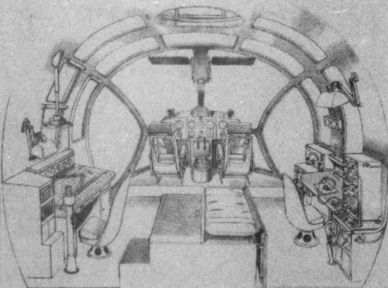
The pilot and second pilot are seated side by side in the nose, with the wireless operator close behind and near the second pilot. On long flights there will be provision for a navigator and a flight engineer. A door is fitted in the underside of the fuselage to obviate the necessity of the crew passing through the passengers' quarters when the machine is on the ground.
The engines selected are air-cooled units of a new type. Each unit is housed completely in the wing with shafts to the airscrews. Cooling is by slots in the leading edge. After passing round the engine the air is discharged at the trailing edge of the wing, adjustable flaps controlling the volume. A tunnel in the wing permits access to the engines during flight.
The proposed wireless installation for long-range work is the Marconi Type AD 67A/6872B/5062C/626B, as used for transatlantic crossings by the Empire boats. Direction-finding and visual course indication are catered for by an additional receiver, a rotatable loop and a visual indicator.
Goodrich pulsating de-icing equipment has been chosen in the first instance.
It is proposed to build a reduced-scale prototype carrying a pilot and observer together with research apparatus. With four Menasco C-4 engines the following data should be obtained: Tare weight 2,000 lb., gross weight 2,840 lb., wing loading 14.2 Ib./sq. ft., power loading (125 h.p. per engine) 14.5 Ib./sq. ft.
MILES X.2 TRANSPORT
Dimensions :
Span 99ft.
Length 78.8ft
Max. cross-section of fuselage 115 sq.ft.
Wing area 1,762 sq. ft.
Aspect ratio 6
Weights and Loadings:
Max. allowable all-up weight 61,128 lb.
Max. wing loading 35 Ib./sq. ft.
Performance: (At 47,555 Ib.)
Top speed at sea level 262 m.p.h.
Top speed at 11.000ft 301 m.p.h.
Top speed at 25,000ft 280 m.p.h.
Max. cruising speed at 11,000ft. 280 m.p.h.
Max. cruising speed at 20,000ft. 200 m.p.h.
Stalling speed at sea level with flaps 70 m.p.h.
Stalling speed at sea level with split flaps 65 m.p.h.
Climb to 11,000 ft 9.6 min.
Absolute ceiling 30,000ft.
* Range at 45 per cent, power in still air 1,200 miles at 11,000ft.
Take-off run at sea level 465 yd.
Top speed on three engines at 11,000ft. 260 m.p.h.
Service ceiling on three engines
* The maximum range at 61,128 lb. will be about 4,300 miles.
- Flight, April 1938
A SUPER MILES
Фотографии

-

Aeroplane Monthly 1982-03 / D.Brown - Project 'X'
Регистрационный номер: U0233 [4] -

OS 1 / H.Cowin - X-Planes
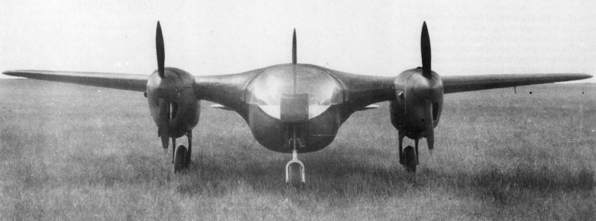
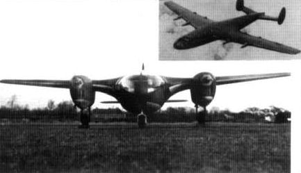
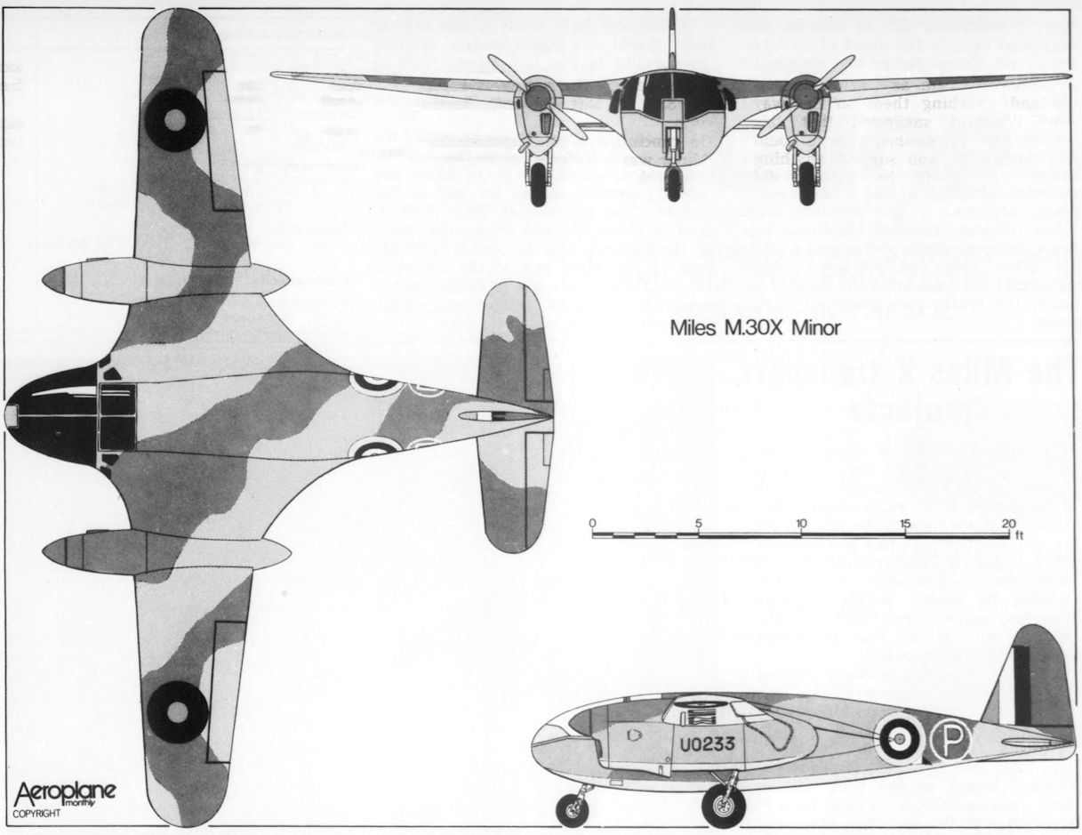
Регистрационный номер: U0233 [4] The Miles M.30 X Minor, U-0233, was a one-off, small scale prototype first flown in February 1942 to test the blended wing/fuselage four- and six-engined airliner concepts drawn up by F. G. Miles in the late 1930s. The M.30 ended its relatively brief career as an instructional airframe with the Miles Aeronautical Technical school. Shown inset is the 50 passenger Miles X II project of 1943. Performance estimates indicated the X II would cruise at 350mph and have a range of 3,450 miles with a full passenger complement. With Miles always considered something of an industry outsider, the X II proposal was spurned by officialdom in favour of what was to become the Bristol Britannia.
-

Aeroplane Monthly 1982-03 / D.Brown - Project 'X'
Регистрационный номер: U0233 [4] -

Aeroplane Monthly 1982-03 / D.Brown - Project 'X'
Регистрационный номер: U0233 [4] View of the aerodynamically smooth, low-drag Miles M.30 X taken in June 1942.
-

Aeroplane Monthly 1982-03 / D.Brown - Project 'X'
A drawing of the spacious pilots' cockpit.
-

-

Flight 1938-04 / Flight
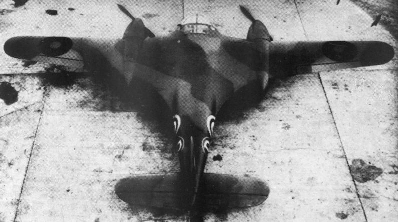
NOT-SO-UNKNOWN QUANTITY: A wind-tunnel model of the projected 300-m.p.h. Miles X.2 four-engined transport. Although the layout is unorthodox in a number of senses no new problems in stability and control are involved.
-

Aeroplane Monthly 1982-03 / D.Brown - Project 'X'
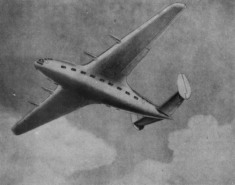
Artists' impression of the Miles M.26 X Transport design.
-

-

Aeroplane Monthly 1982-03 / D.Brown - Project 'X'
Miles M.30X Minor


- Фотографии