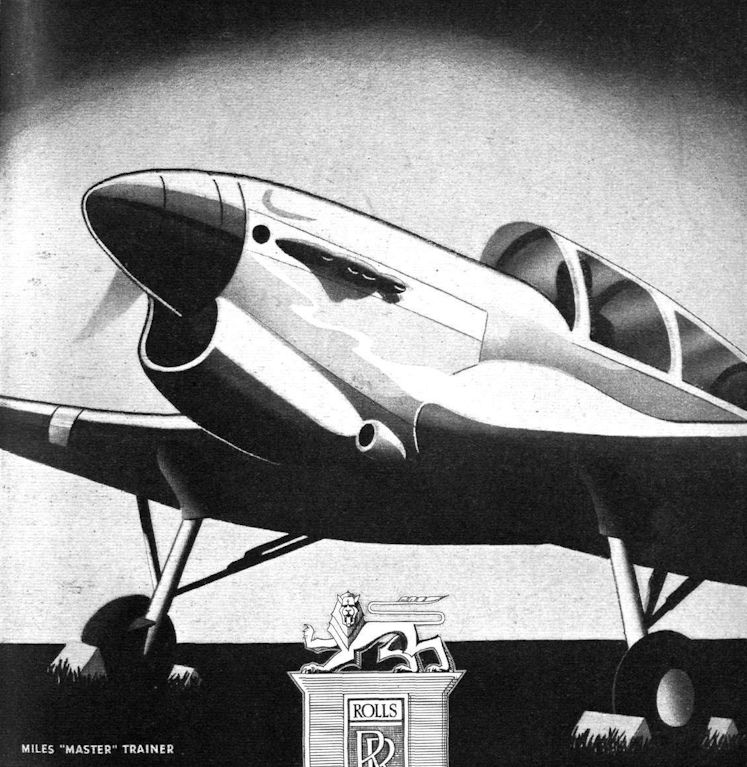
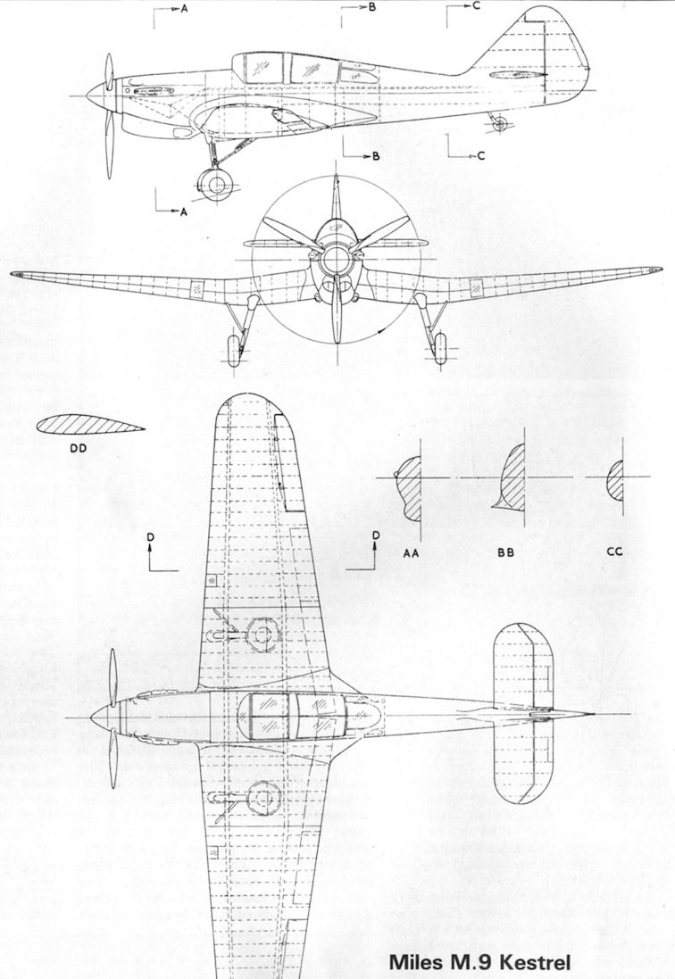
M.9 Kestrel / Master
Miles M.9, M.19, M.24 и M.27 Master
Из-за быстрого совершенствования монопланов в конце 1930-х годов британским ВВС потребовался учебно-тренировочный самолет с характеристиками, близкими к истребительным. Компания "Miles" разработала учебный ДальшеMore>>>
низкоплан с мотором Rolls-Royce Kestrel XVI мощностью 745 л. с. Когда Министерство авиации прекратило финансирование работ, фирма продолжила проектирование на собственные средства. Прототип, названный Kestrel, выполнил первый полет 3 июня 1937 года. Вскоре прототип продемонстрировал скорость всего на 15 км/ч меньшую, чем у Hurricane. По управляемости самолет мало отличался от Hurricane и Spitfire. Не имея других вариантов, Министерство авиации было вынуждено заказать 11 июня 1939 года у компании "Miles" учебные самолеты под обозначением M.9 Master. В конструкцию потребовали внести ряд изменений, а также установить 715-сильный мотор Kestrel XXX, из-за чего максимальная скорость в сравнении с прототипом упала на 113 км/ч. Тем не менее Master все равно оставался лучшим в мире учебно-тренировочным самолетом. Первый из 900 построенных M.9A Master Mk I выполнил первый полет 31 марта 1939 года.
<...>
Flight, July 1939
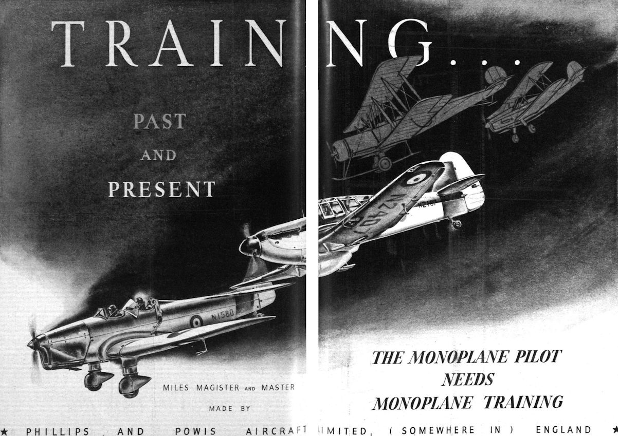
TRAINER DE LUXE
The Miles Master I Described : High Performance with Comparatively Low Power : All-wooden Construction
FIRST deliveries are now being made to the R.A.F. of the Miles Master I two-seater advanced training monoplanes built by Phillips and Powis Aircraft, Ltd., at their Reading works. Fitted with the specially developed Rolls-Royce Kestrel XXX "training" engine, the Master has a top speed of 264 m.p.h., and will enable pupils to "get on a few 'G,’" and generally to accustom themselves to the handling characteristics of contemporary monoplane fighting aircraft, apart from providing for front-gun practice and other branches of instructional flying.
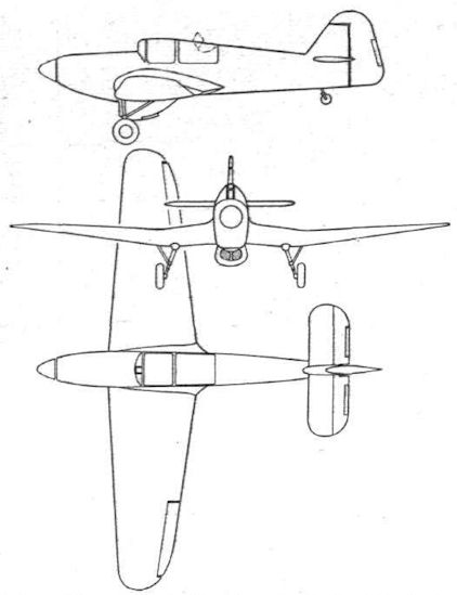
The Master I may he considered as a development of the original Miles Kestrel Trainer, which was capable of 295 m.p.h. or more with a Rolls-Royce Kestrel XVI engine of 745 maximum h.p. Technically, the machine is interesting more for its aerodynamic features than for its structure, which is, in fact, quite orthodox.
The oval-section plywood-covered fuselage is of fine aerodynamic form and of semi-monocoque construction with a large cut-out for the cockpits. The tail unit is of conventional cantilever design, the tailplane being mounted on top of the rear portion of the fuselage, in which position it has a wide attachment base and facilitates recovery from a spin.
Between the tandem cockpits (the pupil occupies the front seat) is a sturdy metal former which, while not projecting beyond the fuselage, offers protection for the crew in the event of a nose-over.
The plywood-covered wing is of N.A.C.A. 230 section and is very deep at the root, though the top spar boom is continued across the fuselage without interfering with the pilot’s use of the rudder bar. The two spars are of normal box construction, but are specially shaped to give the "inverted gull" centre section which is characteristic of the Master. This feature, of course, makes for higher production costs, but it is felt that it is justified on the grounds of performance. The depth of the centre section permits stowage of the fuel tanks and the undercarriage in its retracted position The centre section houses a free-firing machine gun and parachute flares are carried in the outer panels.
Hydraulically operated split trailing-edge flaps extend under the fuselage. These may be depressed to an angle of about 25 deg. for take-off and 90 deg. for landing. Their position is recorded by an electrical indicator on the instrument panel. All electrical leads are housed in ducts.
High-tensile steel, backed up with forgings and magnesium-alloy castings, is used for the engine mounting attachment plates. The Rolls-Royce Kestrel XXX is mounted with Ferodo packings under the bearer feet, and the steel tubular mounting is designed to facilitate engine removal. The complete installation (power unit, vacuum pump and relief valve, hydraulic pump and constant-speed unit) may be taken out of the airframe by removing four main bolts and disconnecting the various leads through the bulkhead.
The Kestrel XXX engine is essentially similar to the Kestrel V, but in comparison is derated for climbing and level flight to provide the longer overhaul life required by a training aircraft, the rated boost being reduced to +1/2 Ib./sq. in. A high take-off power is, however, retained. The actual figures are: rated power, 550 h.p. at 2,400 r.p.m. at 11,750ft.; maximum power, 600 h.p. at 2,750 r.p.m. at 14,500ft.; take-off power, 720 h.p. at +5 lb. boost at 2,750 r.p.m. An ejector-type exhaust system is used.
Hand-starting gear is fitted as standard, and auxiliary drives are provided for a vacuum pump for driving the gyroscopic instruments; a constant speed unit driven from a dual-drive unit at the front of the reduction gear casing; a Lockheed hydraulic pump for undercarriage and flaps; a high-pressure air compressor; and a 500-watt Rotax electric generator.
The airscrew shaft of the Kestrel XXX will accommodate either a Rotol or De Havilland constant-speed airscrew. For the Rotol, which is standardised on the Master, the oil supply passes through an external muff type of feed located in the housing at the front of the reduction gear casing.
Under the fuselage, between the spars, is a low-drag cooling duct for the water and oil systems. This has a variable outlet controlled from the front cockpit.
The main fuel tanks - which, as already stated, are carried in the wing roots - are two in number and hold 36 gallons each. They are readily removable through doors in the lower surfaces of the wing. The oil tank is mounted behind the fireproof bulkhead and has a partial circulator, the shell of which may be replaced to give a different rate of warming-up to suit local conditions. The water leader tank is mounted at the front of the engine above the reduction gear housing.
The retractable undercarriage is of particular interest in that the wheels twist through 90 deg. during retraction into the centre section. There are two independent units which are operated by the Lockheed hydraulic circuit. though emergency pipe lines and a hand pump arc fitted in case of failure of the main pump. A position indicator is interconnected with the ignition switch and the throttle control. Notwithstanding the fact that the electrical indicator is fitted with duplicate bulbs a mechanical indicator is also fitted. The brakes are hydraulically operated, and the wheels and tyres can be Palmers or Dunlops. A cut-out is provided in the instructor's cockpit to render the pupil's brake controls inoperative.
As the Master is an advanced Service trainer, much of the interest centres on the cockpits which are both commodious and comfortable. The front windows of the enclosure slide upwards on channels round the port side, there being a fixed hinge on the starboard side. For use in the air there are emergency catches on both sides, while very large quickly detachable panels are also fitted to permit rapid exit from either cockpit on either side should the machine nose-over on landing. The front windscreen is of moulded Perspex, and is fitted with a Triplex panel in the region of the reflector gun sight to give an optically perfect view of the target. For bad-weather flying two small panels in the screen may be opened. The remarks concerning the emergency exits and the opening of the front windows apply equally to the rear windows. Provision is made for sunblinds under the top portion of the cabin roof.
Of special interest are the arrangements made to ensure that the landing view from the rear seat is comparable with that from the front. A vertical adjustment of the seat of 12in. is allowed instead of the normal 4in., bringing the occupant's head outside the normal fairing line of the cabin roof and giving him a good view over the leading edge. Whilst in this position he is protected by a windscreen which is automatically raised out of the cabin. The adjustment of the rudder bar may be made simultaneously with the change in position of the seats.
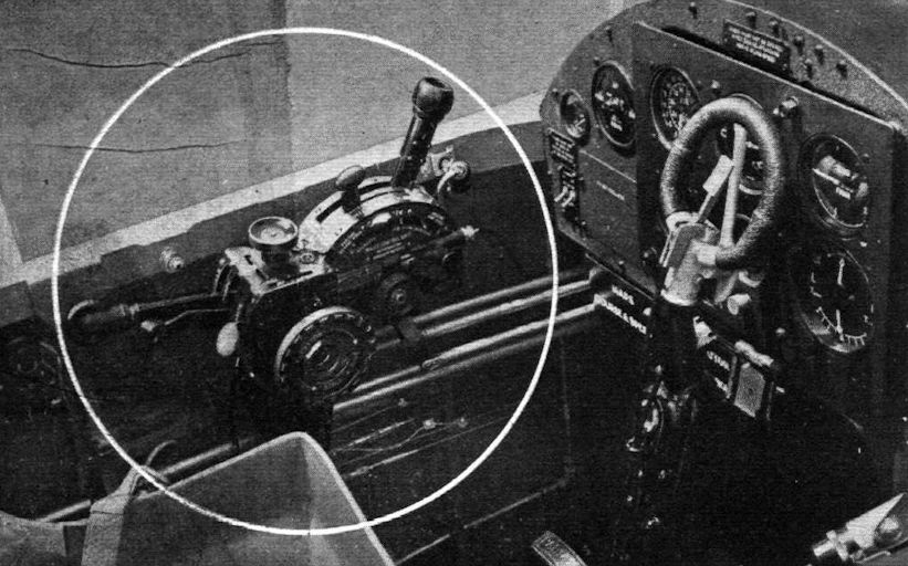
The great majority of the instruments and equipment in the cockpits are visible in the drawing on p. 79, though special reference may be made to the Miles control unit, which incorporates Hobson patents and embodies a throttle, mixture and pitch control, levers for the undercarriage flaps and landing lights, elevator trim wheel and indicator, boost cut-out lever and rudder trim control wheel and indicator. Another feature of special interest is the Craviner fire-extinguisher installation. The extinguisher itself is mounted behind the rear scat, a tube leading forward into the engine bay. This tube is detachable in the front cockpit, and may be used to play on any fire which might occur in that region.
On the floor are the emergency hydraulic valve for working the undercarriage and the emergency hydraulic hand pump. The rest of the hydraulic gear is situated beneath the floor, and is accessible through a removable panel on the underside of the fuselage.
Particularly commendable is the grouping in a single unit in each cockpit of an adjustable rudder bar and control column and the gun-firing gear. Push-pull tubes stabilised by ball-races covered with rubber tyres are used throughout the entire control system. Damped trimming tabs operated by irreversible mechanisms fitted as close to the tabs as possible are fitted to the elevator and rudder. Each has its own indicating system and may be operated from either cockpit.
MILES MASTER I
Rolls Royce Kestrel XXX Engine
Dimensions and Areas
Length 30ft. 8in.
Minimum height (tail down) 10ft.
Span 39ft.
Track 12ft. 3 1/2 in.
Airscrew diameter 10ft.
Wing area 217 sq. ft.
Aileron area 16.72 sq. ft.
Weights
Tare weight 4,160 lb.
Fuel (70 gal.) 525 lb.
Oil (5 gal.) 45 lb.
Pilot, pupil and parachutes 400 lb.
Equipment 145 lb.
Max. permissible weight 5,500 lb.
Performance
Top speed at sea level 209 m.p.h.
Top speed at 10,000ft 244 m.p.h.
Top speed at 15,000ft. 264 m.p.h.
Cruising speed (two-thirds power at 15,000ft.) 230 m.p.h.
Range at 216 m.p.h. (allowing 20 gal. at petrol for ground running, climb and descent) 440 miles
Climb to 15,000ft. 10 min.
Service ceiling 28,000ft.
Take-off run (still air) 293 yd.
landing run (still air, using flaps and brakes) 320 yd.
Landing speed 67 m.p.h.
Flight, November 1939
Britain's Military Aircraft
A Survey of Our Service Machines
PHILLIPS and POWIS
TRAINING aircraft of low and high power are in large-scale production at the Phillips and Powis works.
Larger, faster and of somewhat later design, the Master two-seater advanced trainer has a higher performance than any corresponding training machine in the world.
The oval-section plywood-covered fuselage is of excellent aerodynamic form and of semi-monocoque construction. Between the tandem cockpits (the pupil occupies the front seat) is a sturdy metal former which offers protection for the crew in the event of a nose-over. The plywood-covered wing is of N.A.C.A. 230-section and of inverted-gull form. Hydraulically operated split trailing-edges extend beneath the fuselage.
A Rolls-Royce Kestrel XXX engine, rated at 550 h.p., is fitted as standard. This drives a Rotol constant-speed airscrew.
The retractable undercarriage is of particular interest in that the wheels twist to 90 deg. during retraction into the centre section. The usual indicators are fitted.
At 15,000ft. the Master is capable of 264 m.p.h. and cruises on two-thirds power at 230 m.p.h. The climb to 15,000ft. takes ten minutes and the service ceiling js 28,000ft.
Phillips and Powis Aircraft, Ltd., The Aerodrome Reading, Berks.
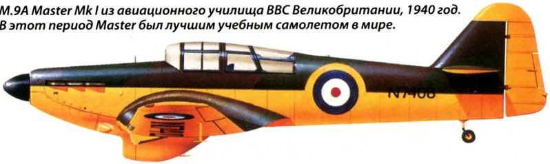
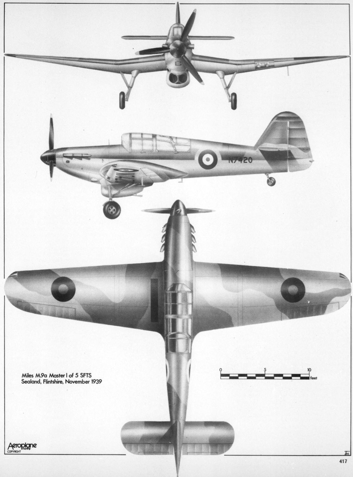
M.9A Master Mk I из авиационного училища ВВС Великобритании, 1940 год. В этот период Master был лучшим учебным самолетом в мире.
Kestrel
The Miles R.R. Trainer (Rolls-Royce "Kestrel" engine).
A "private-venture" machine, the new Miles advanced fighter-trainer is powered with a Kestrel XVI which gives it a top speed of 290 m.p.h.
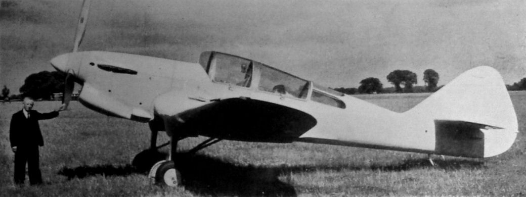
The private-venture Miles Kestrel, later registered U-5, was well ahead of its time.
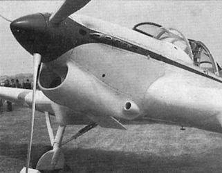
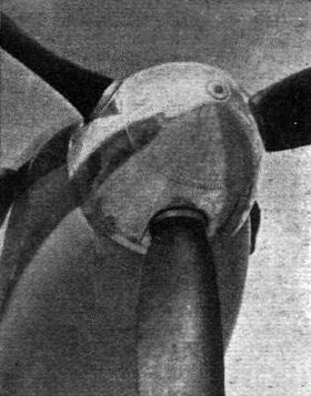
A close-up of the installation of the Rolls-Royce Kestrel XVI and the Kestrel's well-streamlined nose.
An advanced Kestrel XVI installation in the new Miles trainer/general-purpose military monoplane. The coolant is ethylene glycol.
NOT SO PRIVATE: Child of a designer who, until comparatively recently, has concentrated on the production of private-owner types, the new Miles high-speed Service trainer has a number of features which would make it, in 200 h.p. form, an attractive device for the sporting pilot with (very) ample means. Capable of 295 m.p.h., the Miles Kestrel Trainer has great potentialities as a first-line military type. The engine is a Rolls-Royce Kestrel XVI.
The Miles R.R. Two-seat Fighter Training Monoplane (Rolls-Royce "Kestrel XVI" engine).
The Miles-Rolls-Royce advanced trainer-general-purpose-fighter-bomber-reconnaissance monoplane does about 290 m.p.h. with a 690/750 h.p. fully supercharged Kestrel XVI.
The Miles Kestrel Trainer which would make a very good first-line two-seater fighter, having a speed of 295 m.p.h.
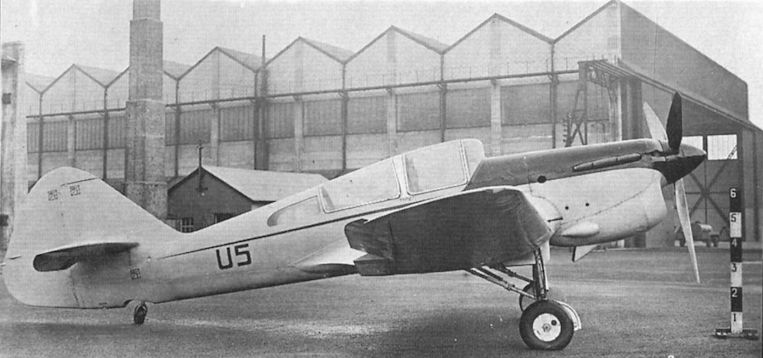
The Kestrel as U 5, with deepened radiator but before modification of the canopy.
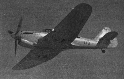
The Kestrel with the deeper and more bulbous radiator fairing. It originally had a much sleeker but less accessible installation, with which it made its debut at the 1937 RAF Display at Hendon. Powered by a supercharged 745 h.p. Rolls-Royce Kestrel engine, U 5 had a maximum speed of 296 m.p.h. at 14,500ft - only 15 m.p.h. slower than the front-line Hawker Hurricane.
Master
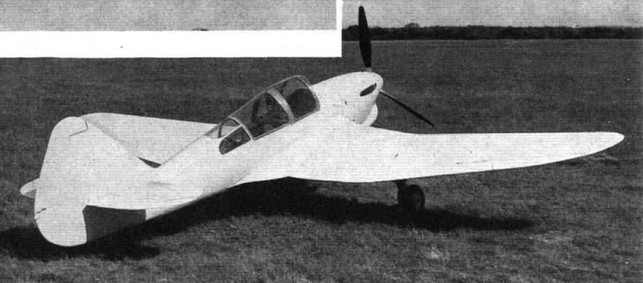
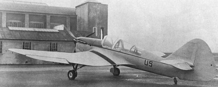
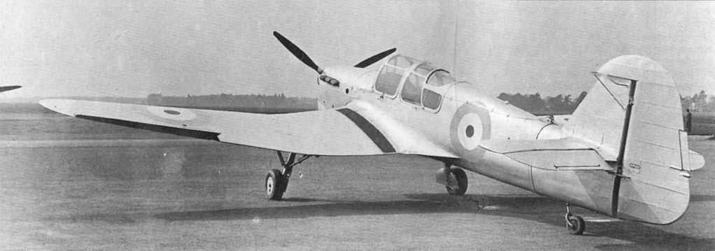
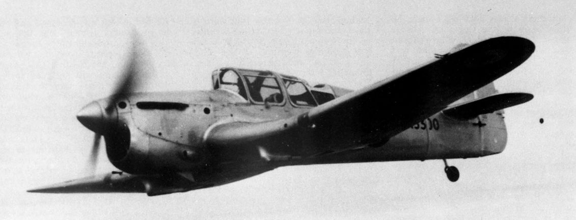
The Kestrel after it became the Master prototype. Comparison with the picture of the Kestrel reveals the Master's deeper aft fuselage, redesigned fin and rudder, taller windscreen and modified rear canopy.
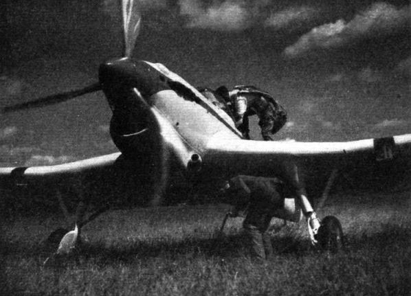
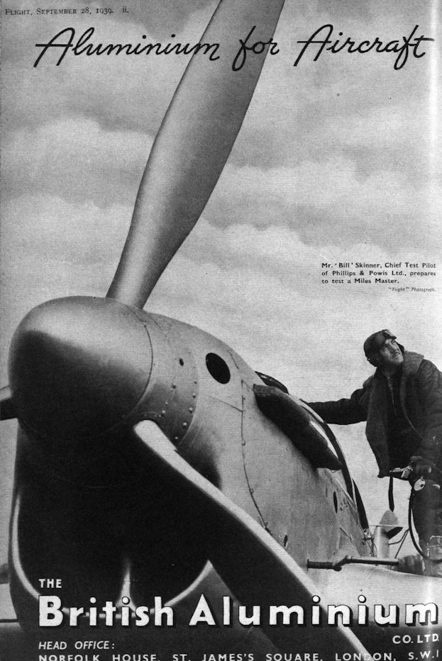
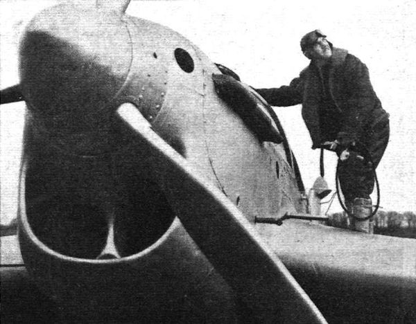
Mr. ‘Bill’ Skinner, Chief Test Pilot of Phillips & Powis Ltd., prepares to test a Miles Master.
The late Mr. Skinner about to start in a Miles Master.
Another view of the Kestrel after modification as the Master prototype. The inverted gull wing allowed short, sturdy undercarriage legs to be used.
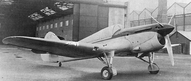
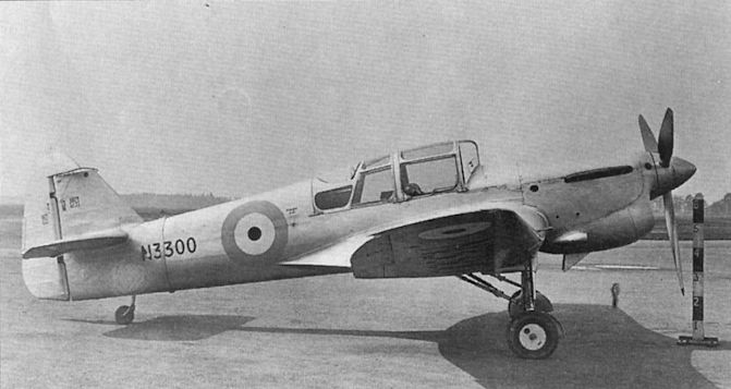
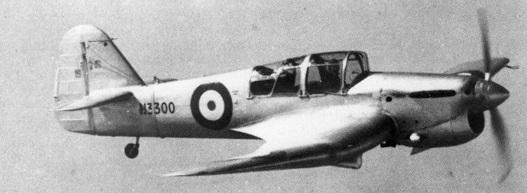
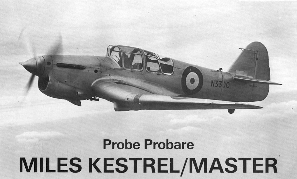
In the transition from prototype to production Master, the radiator was moved from the chin installation seen on N3300 here to a new and distinctive position under the mainspar.
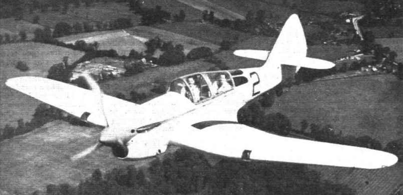
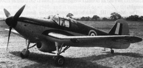
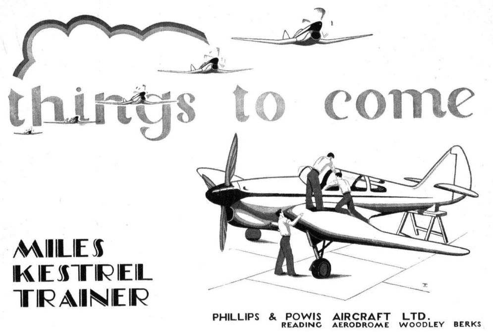
A delightful impression of the prototype Miles M.9A Master I two-seater advanced trainer (Rolls-Royce Kestrel XXX).
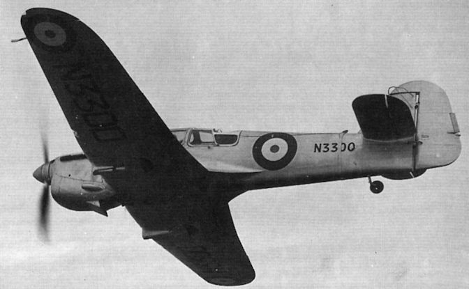
View of the Master prototype N3300 in flight during 1938-39. The extended rear fuselage and production-standard tail surfaces eliminated the directional hunting encountered during early Martlesham trials.
N3300, the first prototype Master I, converted from the private venture Kestrel prototype, was delivered to the RAE in October 1938.
The Miles Kestrel after modification as the prototype Master, N3300. Initially registered U 5 and flown for the first time on June 3, 1937, the Kestrel reappeared as N3300 in 1938. The strap visible around the rear fuselage in this photograph is part of the anti-spin parachute attachment; a release cable may be seen running forward to the cockpit.
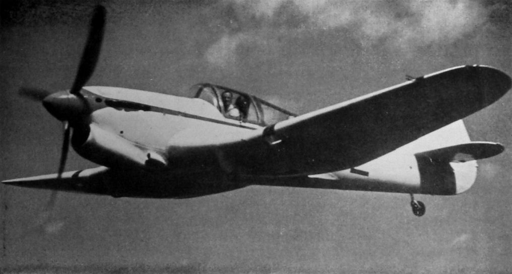
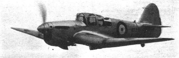
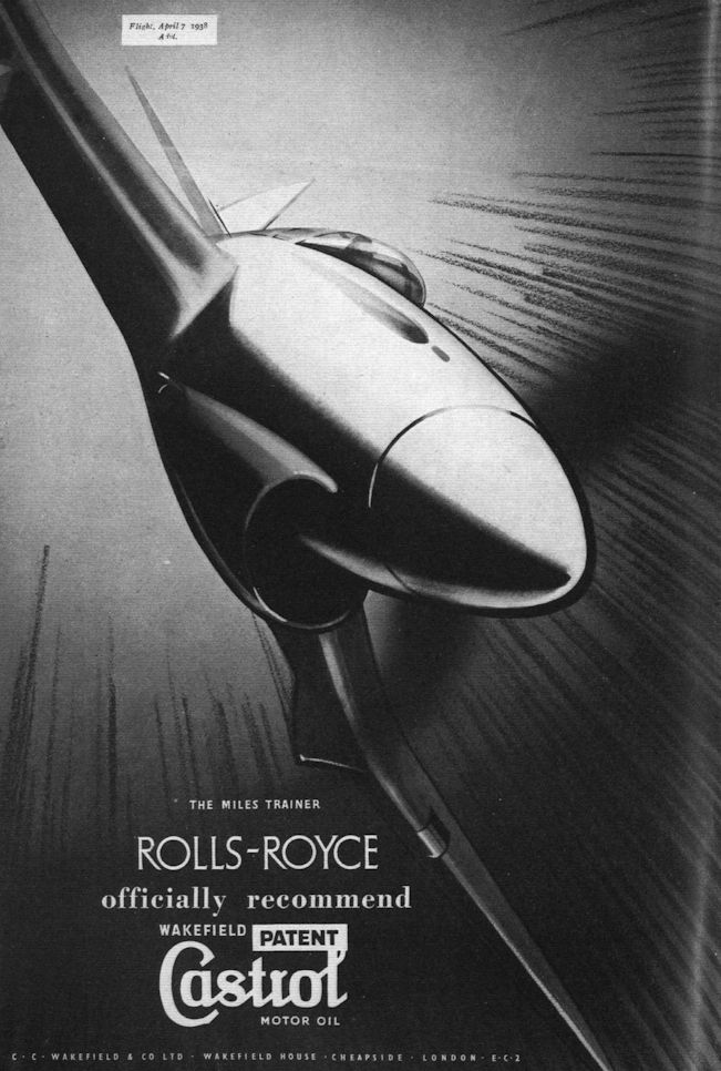
MASTERLY: The Miles Master high-speed advanced trainer as now in large-scale production for the R.A.F. Actually, the machine seen here (with Mr. Skinner taking it up to 25,000ft. for tests), is the revised prototype with Rolls-Royce Kestrel XVI engine which gives it a top speed of 295 m.p.h. The production version will have the less powerful Kestrel XXX and will do nearly 270 m.p.h.
THE NEW MASTER: In its production form, the Miles Master two-seater advanced trainer (Rolls-Royce Kestrel XXX) has a re-arranged radiator and certain other minor improvements.
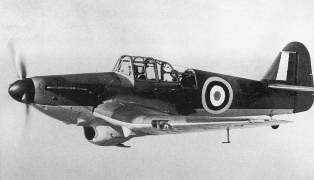
С мотором жидкостного охлаждения и огромным радиатором Master Mk I смотрелся необычно. Большинство самолетов Master эксплуатировалось в Силэнде, Халлавингтоне и Монтроузе.
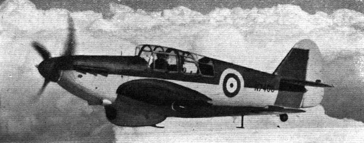
A fine study of Master I N7547, with the mouth-like radiator intake and undercarriage “knuckle” well shown.
Stages in the evolution of commercial aircraft. The Hampstead.
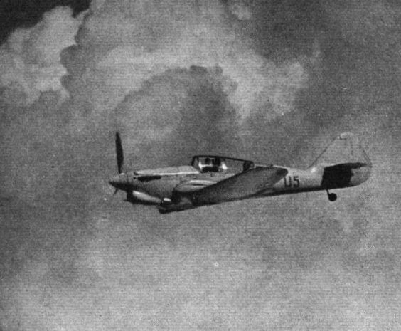
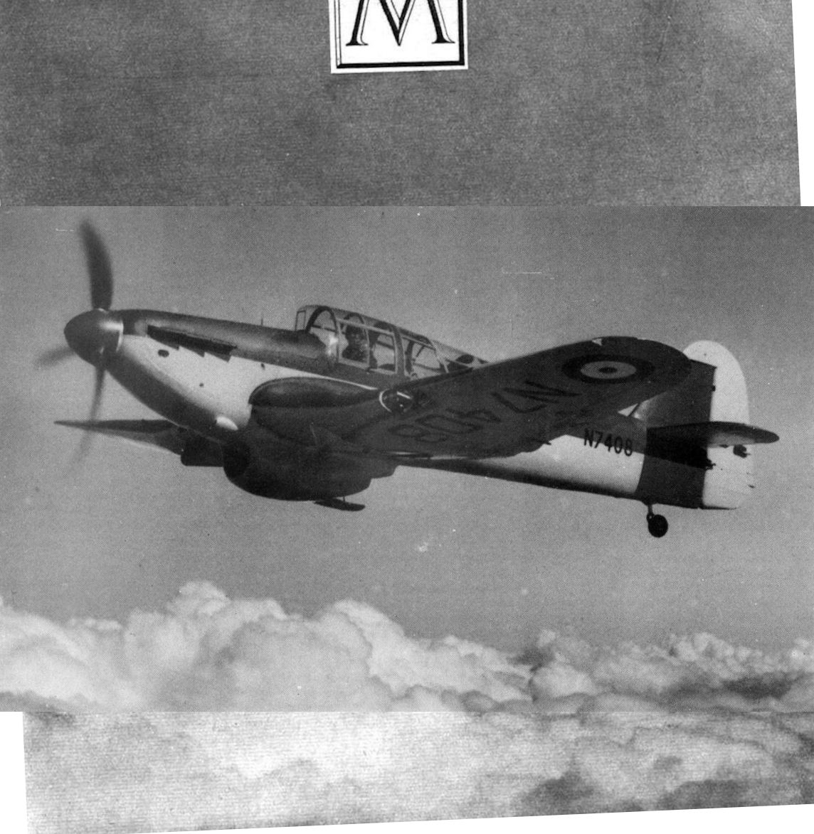
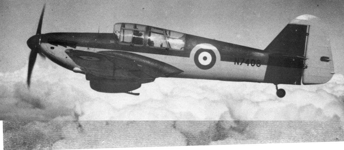
Mr. H. W. C. Skinner, chief test pilot, does a "straight and level" above the clouds on a production Master.
The first production Miles Master I, N7408, was the first of 900 Mk Is delivered to the RAF, the first aircraft entering service in mid-1939.
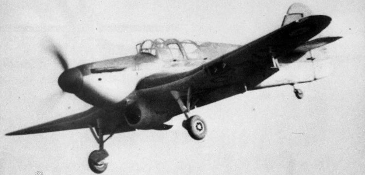
N7420 on finals, with full flap and undercarriage down.
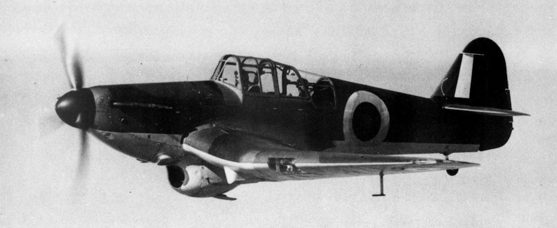
MASTERFUL APPROACH: A Miles Master two-seater advanced trainer (Rolls-Royce Kestrel XXX) approaches to land with flaps down. A considerable number of these machines is already in service.
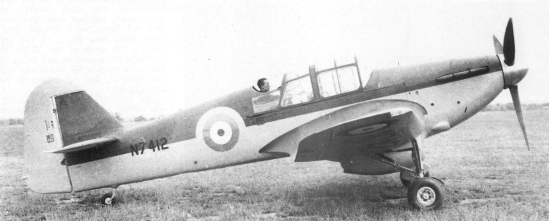
Master N7412, seen with the rear seat raised, was later converted to become the prototype M24 single-seat Master Fighter.
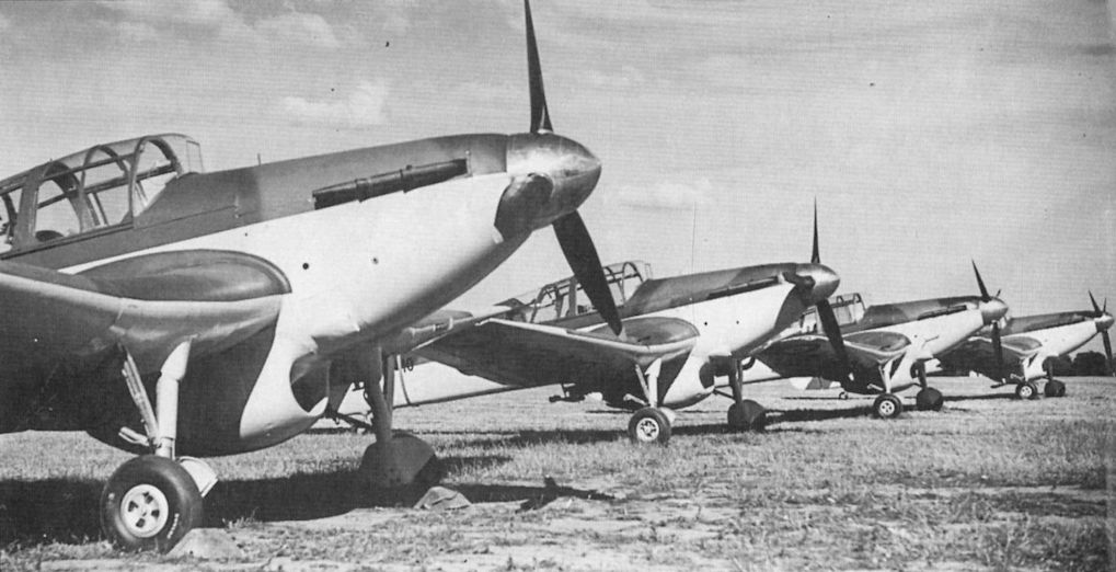
Miles Master advanced-training monoplanes with Rolls-Royce Kestrel XXX engines. The Kestrel XXX has been specially developed to meet training requirements.
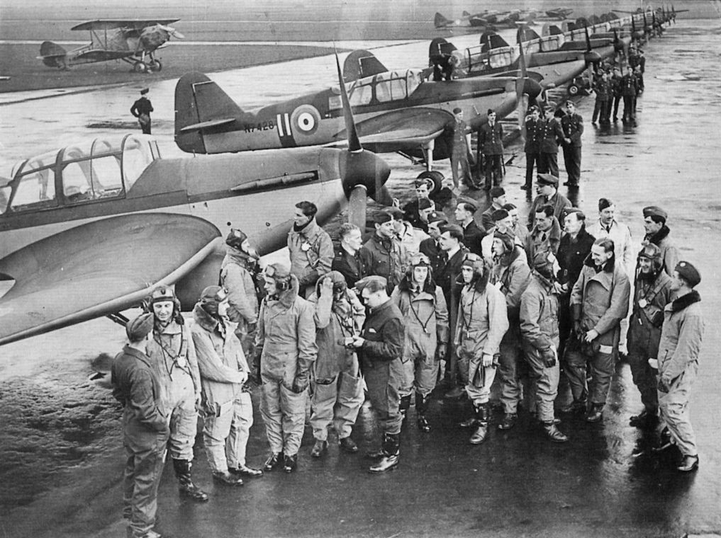
Line-up of Master Is. The prototype first flew in 1938 but by the time war broke out in September 1939 only a handful were in service. Masters of No 5 EFTS are pictured here.
Factory-fresh Masters, 1939. N7410, second from the front, was delivered to the A & AEE and became 2551M in March 1941.
ADVANCED TRAINERS: Flying training schools are now receiving batches of Miles Master I advanced training monoplanes with Rolls-Royce Kestrel XXX engines. These machines are not only fast and “easy on the eye” but reproduce more nearly than any comparable type the characteristics of the modern fighter.
Closely resembling the Miles M.9 Kestrel, the Master I was powered by a derated Rolls-Royce Kestrel XXX, making it 70 m.p.h. slower than its predecessor. Its handling characteristics made it an ideal fighter trainer.
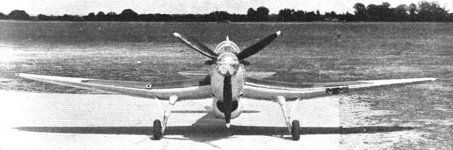
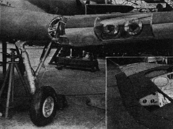
The nose of a Miles Master advanced trainer (Rolls-Royce Kestrel XXX). It will be seen that the radiator is mounted under the fuselage behind the engine.
There is no doubt that, in the Master, Service trainees will have "a real aeroplane." The top speed of over 260 m.p.h. can be credited on examining this view.
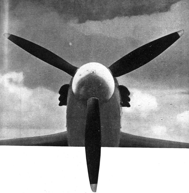
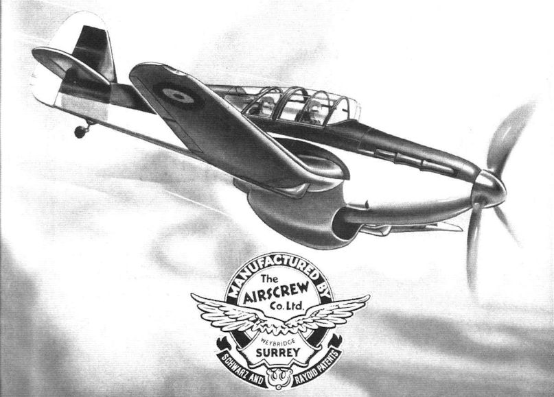
A V.D.M. spinner on the Miles Master
Undercarriage and landing light installation. The wheels turn 90° during retraction.
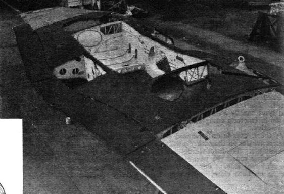
The complete wing of a Master showing the formation of the centre gulled portion.
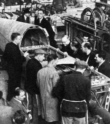
SIR KINGSLEY WOOD looks into a Miles Master airframe on its jig during his visit to the new Phillips and Powis factory. The fuselage appears to have been modified to accommodate the new tail unit.
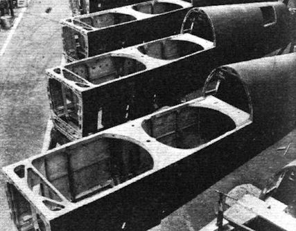
Semi-monocoque fuselages in train for Masters.
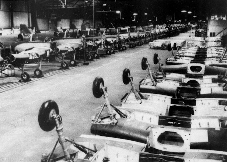
Production at Woodley, with centre sections ready for transfer to the advanced track assembly line opposite. This system enabled the first 500 Master Is to be delivered between July 1939 and September 1940, a production rate of 33 machines per month.
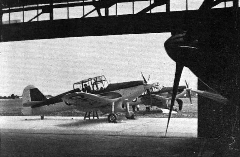
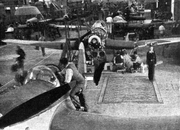
Miles Masters (Rolls-Royce Kestrel XXX) on the production line at Reading.
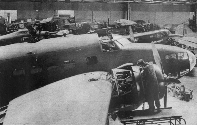
An ATA maintenance hangar "somewhere in England" in 1942. Behind the Lockheed Hudson are a Hurricane, Demon K4411, an Oxford, Master W8905, an Argus, a Tutor, a Havard and the tail of an Anson. All were used either for the training or movement of ATA pilots.
M.24
The Miles M.24 makeshift six-gun fighter developed for emergency use during the Battle of Britain.
THE MILES MASTER is fitted with an Engine Control Unit, designed and constructed jointly by H. M. Hobson (Aircraft and Motor) Components Ltd. and Phillips & Powis Ltd. under HOBSON PATENTS. It incorporates in one unit the following Controls
- THROTTLE - MIXTURE - BOOST CUT-OUT - FLAPS - C.P. AIR SCREWS
- LANDING LIGHTS - ELEVATOR - RUDDER TRIM - BOMB RELEASE
- RETRACTABLE UNDERCARRIAGE WITH THROTTLE OPERATED WARNING DEVICE
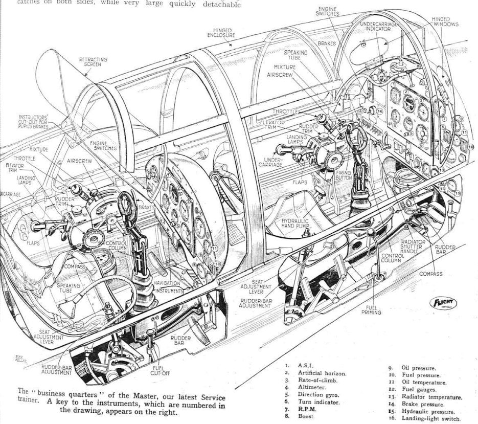
The “business quarters” of the Master, our latest Service trainer. A key to the instruments, which are numbered in the drawing, appears on the right.
A closeup of the pupil and instructor positions in the Master I.
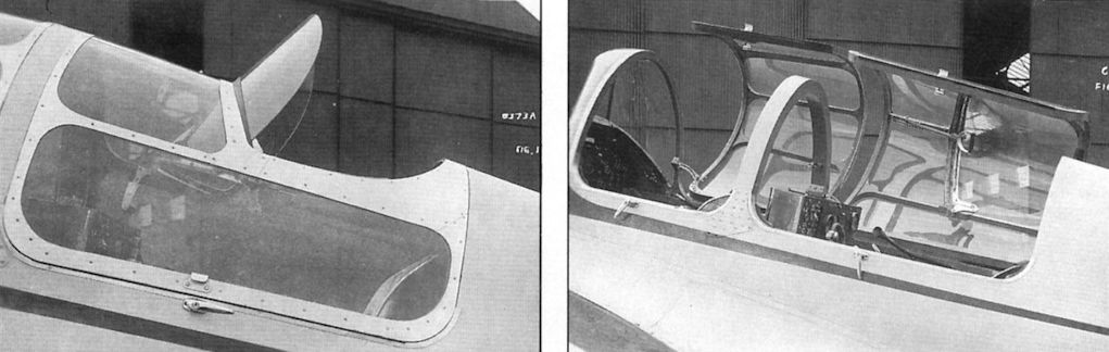
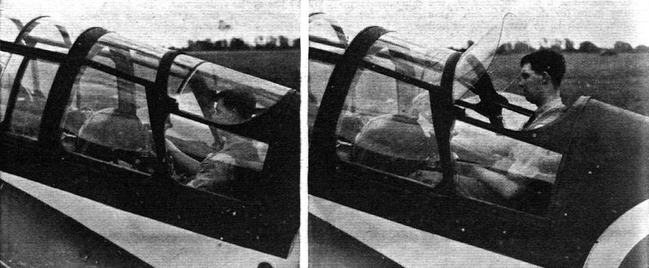
Left, the Kestrel’s rear cockpit after the first modification to raise the roof. Right, the Kestrel with the front hood and modified instructor's hood open, showing the operating handle for the hinged aft windscreen.
Showing how, for landing, the instructor can raise himself to obtain a good view. The raising of the windscreen is automatic.
The retractable windscreen of the Miles Master lifted automatically when the instructor raised his seat, giving his improved vantage point some protection from the elements.
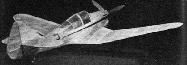
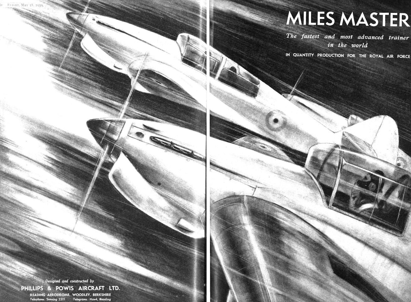
The flying scale model - Miles Master
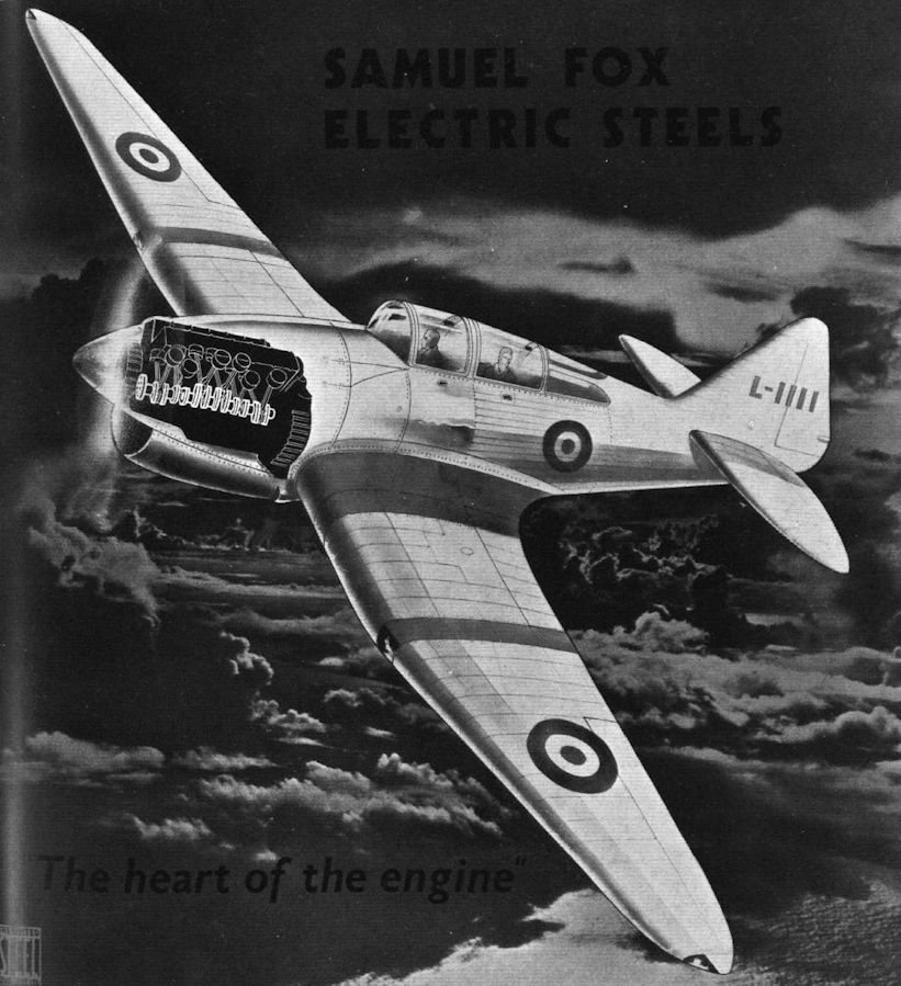
MILES MASTER The fastest and most advanced trainer in the world IN QUANTITY PRODUCTION FOR THE ROYAL AIR FORCE
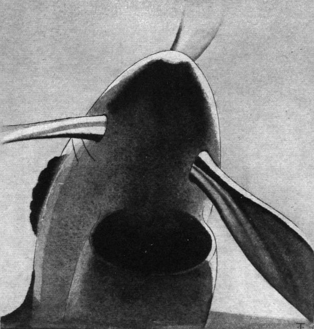
The Basking Shark is extremely efficient from the streamline point of view, but then the Basking Shark has been developed for efficiency, just as the Miles Kestrel Trainer has been developed, by careful elimination of the unessential.
ROTOL VARIABLE PITCH AIRSCREWS are fitted on ROLLS-ROYCE KESTREL XXX ENGINES installed in the MILES MASTER AIRCRAFT manufactured by Phillips & Powis Aircraft Ltd., of Reading
A typical control run on the Master, showing the application of the neat rubber-tyred ball races.
Miles M.9a Master I of 5 SFTS Sealand, Flintshire, November 1939


 Wikipedia