Самолет с изменяемым размахом крыла конструкции Махонина
Русский инженер Иван Иванович Махонин родился в 1885 году в Санкт-Петербурге. В годы Первой мировой войны он организовал собственное "бюро изобретений", которое занималось разработкой новых видов вооружений (реактивных снарядов, бронебойных пуль, авиационных торпед) и различной техники. После революции 1917 года сотрудничал с Советской властью, принимал активное участие в восстановлении железнодорожного транспорта России, однако впоследствии "потерял доверие власти" и в 1921 году эмигрировал во Францию.
В эмиграции он разработал проект самолета с изменяемым размахом крыла MAK-10, который совершил первый полет в Виллакубле 11 августа 1931 года. Самолет представлял собой моноплан со средним расположением крыла, внешние части консолей которого телескопически втягивались внутрь корневых частей - размах крыла изменялся от 13 м до 21 м, а площадь - от 19 м2 до 33 м2. Вскоре выяснилось, что силовая установка самолета - один двигатель Lorraine 12Eb мощностью 480 л. с. - недостаточно мощная, поэтому в конце 1934 года на машину установили двигатель Gnome-Rhone K-14 мощностью 950 л. с. В таком виде самолет стал именоваться MAK-101, первый полет он выполнил в 1935 году - машина могла теперь достигать максимальной скорости 375 км/ч. Доработка и испытания продолжались до 1941 года, последние 6 месяцев - под наблюдением немецких специалистов в Рехлине. Во время одного из налетов авиации противника MAK-101 был уничтожен (по другим данным, это сделал летчик-испытатель).
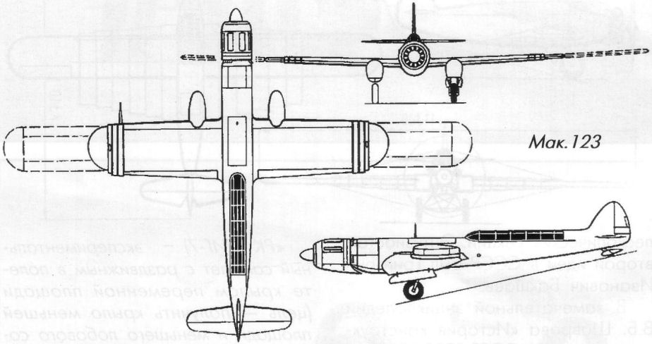
После войны И. И. Махонин начал работы над новым проектом - MAK-123, самолетом обычной конструкции со звездообразным ПД BMW 801 мощностью 1800 л. с., рассчитанном на пилота и трех пассажиров. Первый полет он выполнил в 1947 году, но получил повреждения, и на том работа Махонина закончилась.
Показать полностьюShow all
Flight, May 1932
The Makhonine Way
THE very brief account which Mr. Heinze gives of the wing designed by Prof. Schmeidler, of the Breslau College of Engineering, is not sufficiently technical to enable one to form any reliable estimate of the net gain in speed range. Devices of this kind must of necessity form a compromise between the aerodynamic advantages to be gained and the extra weight of the wing structure and its operational mechanism. The statement that, according to the inventor, the difference in take-off run with wing closed and wing open is very marked does not really prove anything. It was to be expected that a wing of increased area and camber would give a greater lift than the same wing "closed up." The real test is whether a wing of fixed area and camber could have given the same performance.
On the face of it one would say that Prof. Schmeidler has attacked the problem "from the wrong end." It was, we believe, Mr. C. C. Walker, of the de Havilland Company, who once said: "Increased chord is no cure for an overloaded machine, but increased span is." In this case it is not, of course, a question of an overloaded machine, but the same principles apply. It will be granted that by combining variable camber with variable chord, Prof. Schmeidler has found a scheme which would be expected to be more effective than a mere increase in chord. Whether or not the extra weight involved leaves a balance in favour of the wing is impossible to guess without much fuller data than Mr. Heinze supplies.
To us it seems that if one is to derive any worth-while benefit from a variable wing, the better way to tackle the problem is via the variable span. After all, in the light of modern aerodynamic theory we know that span loading plays a very important part in the efficiency of a wing, especially at low speeds, where the span loading determines the induced drag.
Last year a machine was built in France for the purpose of testing out such a wing arrangement. The design owed its inception to M. Makhonine, who is, we believe, a Russian domiciled in France, and who succeeded in convincing the French authorities that his idea was worth a trial.
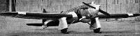
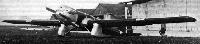
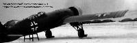
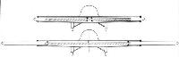
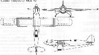
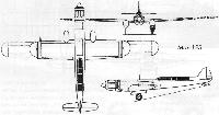
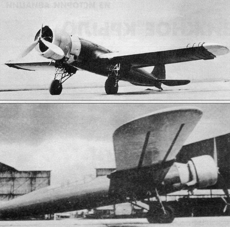
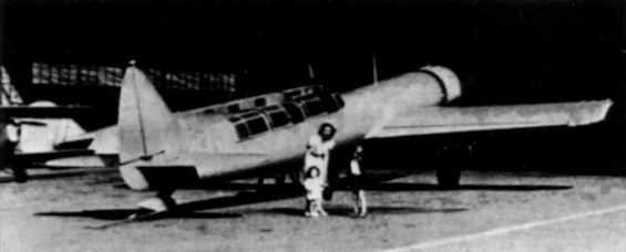
The Makhonine machine is shown in the following photographs, and the general "scheme" is indicated in a very diagrammatic sketch which we reproduce by courtesy of our excellent French contemporary Les Axles.
The sketch is purely diagrammatic, and probably bears little enough resemblance to the actual wing, but it does indicate the general principle of the Makhonine wing, which is an inner wing root into which the outer wing portions telescope. But there is more to the Makhonine system than that. The diagram shows that inside the wing is a fixed beam or spar anchored at its centre to the fuselage. When the wing tip portions are in their "out" position, this beam assists the hollow wing roots in carrying the load, although from the fact that it is on the centre line, and therefore has no great depth on each side of the neutral axis, the beam cannot be very efficient. Its main function would seem to be rather that of relieving stresses by changing the spar from a lever of one order into a lever of another order.
In actual construction it seems likely that instead of the four rollers shown in the diagram there are many rollers, and one imagines that the wing has probably been built as a multi-spar construction, as this would appear to lend itself better to the Makhonine scheme than a two-spar structure.
Few data relating to the Makhonine machine are available, but at least the machine has flown, although we have no information relating to the useful load carried. The first test flights were made in August of last year, but since then nothing has been heard of the machine. Of the reason for this we are ignorant at the moment.
The few data available indicate that the variation in wing span and wing area is such that a marked effect on performance would be expected. For example, with the wing tip portions in the "out" position the span is 21 metres (68 ft. 10 in.) and the wing area is 33 sq. m. (355 sq. ft.). When the wing tips are withdrawn into the wing, the span is reduced to 13 metres (42 ft. 7 in.) and the wing area to 19 sq. m. (205 sq. ft.). During the test flights last year the gross weight was only 2 800 kg. (6,160 lb.). With this load the machine is reported to have got off very well with the wings spread, and to have landed successfully with the wings drawn in. The real test, however, will be the full-load one, when the designed gross weight is 5 000 kg. (11,000 lb.). In that condition the wing loadings will be 31 lb./sq. ft. and 53.7 lb./sq.ft. respectively. As the machine is fitted with a Lorraine engine of 450 h.p., the power loading at full designed gross weight would be 24.5 lb./h.p. The designer estimates that with these loadings the machine would just get off, and would fly at the reduced wing area, although if a landing had to be made shortly after the take-off it would, of course, be necessary for the pilot to spread the wings and also to jettison his fuel.
It is reported that during the test flights at 6,160 lb. gross weight the pilot landed the machine with wings retracted, i.e., at a wing loading of 30 lb./sq. ft., which was near enough the same wing loading as the fully-loaded machine would carry on the full area at the maximum designed gross weight.
The difference between the gross weight at which the machine was flown last year and the designed gross weight is 4,840 lb. If it is assumed that the useful load then carried was fairly small (as it probably was for preliminary tests) and we disregard it in our consideration of the machine, this figure represents the disposable load available. If the whole of it were in the form of fuel, it would represent some 650 gallons, which should give a machine with as high a cruising speed as the Makhonine machine should have with reduced area a very substantial range. Or if only a portion of the load were used for fuel, and the range reduced, the pay load should attain a very high figure.
One may think of many reasons why nothing more has been heard of the Makhonine machine. Funds may have run low, or trouble may have been met with in the controllability (the ailerons are, of course, placed near the outer ends of the fixed wing portions), or again the wing may not have been found strong enough to carry the full designed load, or, if strong enough, may have been found to deflect to such an extent under load that the operation became difficult or impossible. Or a host of other possibilities present themselves in connection with such a radical change in design. Until definite information is released it is impossible to say. But at any rate one admires M. Makhonine for a very daring and ingenious piece of work, and hopes that he will be able to continue his interesting experiment.
Показать полностьюShow all