Самолеты Huff-Daland
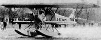
Компания "Huff-Daland Aero" была основана Томасом Хаффом и Элиотом Даландом в 1920 году. Первоначально она носила название "Ogdensburg Aeroway Corp", а позже, но до 1925 года, - "Huff-Daland Aero Corp ". В 1924 году компания стала первой в мире, предоставлявшей услуги по опылению полей с самолетов. Аэропланы были собственной конструкции, но основным самолетом стал биплан Huff-Daland HD.4 Bridget. Эта машина оказалась настолько удачной, что ее в качестве учебного использовала Авиационная служба Армии США. Были заказаны три самолета, получившие обозначение TA-2 (Trainer, Aircooled 2) и оснащенные звездообразным двигателем ABC Wasp мощностью 140 л. с. Вскоре один из них был модифицирован - на него установили двигатель Lawrance J-1 мощностью 220 л.с. (новое обозначение самолета - TA-6). Пять в целом похожих самолетов с двигателями Wright-Hispano E2 мощностью 190 л.с. были приобретены военными - первоначально они обозначались TW-5 (Trainer, Watercooled 5). Но позже, после модернизации, они получили обозначение AT-1. Еще 10 машин AT-1 были построены компанией Хаффа и Даланда в новом виде. Один AT-1, который использовался Армией США в ходе различных экспериментов, был переобозначен как AT-2. Еще три самолета, в целом схожих с TW-5, были приобретены ВМС США для учебной подготовки, они получили обозначение HN-1. Обозначение HN-2 было присвоено трем схожим с ними самолетам TA-6. Еще три самолета, идентичные HN-1 за исключением сменного шасси (колесное или поплавковое), были приобретены ВМС США в качестве самолетов разведки и наблюдения, они получили буквенное обозначение HO.
Показать полностьюShow all
Flight, March 1922
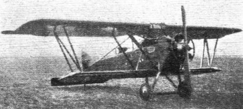
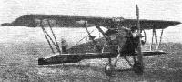
THE HUFF-DALAND BIPLANE
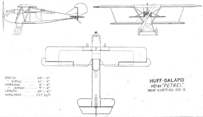
HUFF, Daland and Co., of Ogdensburg, N.Y., have recently produced two interesting machines incorporating thick-section wings and several novel constructional features. These two machines are known as the H.D.9A two-seater Army training biplane, and the H.D.8A "Petrel" three-seater commercial biplane. The former was brought out to meet the United States army requirements of a Type 14 air-cooled-engine training 'plane, and was fitted with a 100 h.p. Anzani engine, whilst the latter is a further development of this machine incorporating the Curtiss O.X.5 water-cooled engine. It was produced to meet the demand for a strong, moderate-powered three-seater of simple construction, capable of being operated and maintained at the lowest possible figure.
Except for the changes necessitated by the change of engine and a slightly more streamlined fuselage in the H.D.8A, both of these machines follow the same general type of construction, and the following description more or less applies to both.
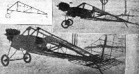
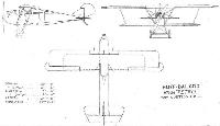
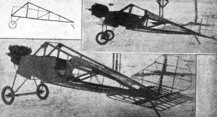
It is in the fuselage that the most interesting feature of the H.D. machines is to be found. A somewhat unusual, but at the same time exceedingly simple, method of construction has been employed on all the H.D. models - a form of construction differing from the orthodox braced girder type, as may be seen on referring to the accompanying illustrations. It will be seen that the upper and lower longerons in this case form a triangulated truss between the main planes and the tail, the apex being at the latter - very much after the fashion of the outrigger tail booms of the "box-kite" biplane. Each upper member, or longeron, runs from the rear spar of the top plane, where it is connected with the corresponding lower member by two struts, meeting the latter at the location of the lower plane rear spar and the foremost extremity - at engine partition - respectively. Other vertical struts connect the upper and lower members at the end of the cockpit, at the tail (leading edge) and midway between these points. Auxiliary longerons extend rearwards from the top of the transverse engine bulkhead and form the pilot's and passengers' cockpit. Aft of the latter the auxiliary longerons are decked over by means of stringers, whilst a curved bottom is similarly formed on the lower members.
By this form of construction tail loads and wing loads are carried by direct paths through these rigid members in place of the usual struts and wires. It also greatly reduces the number and weight of parts, whilst the time taken in assembly is likewise reduced. The only wire cross-bracing is between the lower longerons, and these wires are threaded on the ends and carried through holes in the longerons at the strut junctions to a small steel plate and nipple. The use of a large number of turnbuckles is thus obviated.
Veneer is used for covering the fuselage from the engine plate to a point aft of the cockpit, and access to the latter is by means of side doors which in no way weakens the fuselage structure. The rest of the fuselage is fabric-covered.
The mounting of the 10-cylinder Anzani engine follows that employed on the earlier training model turned out by this firm - the H.D.4. It consists of a circular nose-piece to which the engine is bolted, supported by a system of tubular trussing connected to the forward bulkhead at the longeron junctions. Four large pins connect the unions of these tubes at their attachment to the fuselage, making the removal of the engine unit an easy matter, and allowing the engine to be swung backward for inspection by withdrawing two pins on one side or the other.
In the case of the Curtiss O.X. 5, in the H.D.8A, the mounting is as follows :- The fuselage terminates with a solid bulkhead and fire-shield, upon which six large pin fittings are mounted. The tubular engine mounting itself, made up in two halves, right and left, is bolted to these fittings without the need of any cross wires or external bracing for support. It may be detached with the engine as a unit in case of quick changes on the aerodrome, while in the shop the engine can be slipped into place along the bearers without having to disturb any of the accessory fittings. The cowling is hinged aft of the engine top and bottom, so that it may be raised or lowered entirely out of the way and yet not require complete removal.
The wing section employed in both machines is the Gottingen 387. Both upper and lower wings are built upon veneer-sided box spars. The veneer sides terminate at points about one-fifth of the span from the wing tips, the remaining portion of the spar being formed by a Warren truss supporting the upper and lower members of the spar. The ribs are of special construction and novel design. Owing to the great wing-depth two independent girders of basswood are used to form the top and bottom flanges, fastened together by suitably spaced vertical members. The fabric is sewed separately about the upper and lower parts, giving added security by forming an independent attachment for both surfaces. Sand texts have been carried out on these ribs beyond the required f.s. of 8 without sign of failure. The entering edge is of veneer.
A double set of drift wires, which independently truss the upper and lower members of the spars, give unusual rigidity. The top plane is supported with a rigid connection between the rear afar and the apex of the fuselage longeron, and three additional struts on each side. These are located as in the Fokker D-VII biplanes, one extending from the lower fuselage longeron at junction with lower rear wing spar to the upper rear wing spar at the end of the centre section; a second strut extends from the forward extremity of the lower longeron - at junction with front chassis strut - to the front top wing spar, corresponding to the rear spar attachment. The third strut runs from the top of the second to the forward extremity of the auxiliary fuselage longeron. These struts, as well as the "N" interplane struts, are of streamline steel tubing, the "N" struts being adjustable for the correction of incidence. The lower wing fits into a recess formed in the fuselage bottom, and is secured by four large bolts - a system also similar to that employed on the Fokker D-VII.
Ailerons are fitted to the top plane only, and are of the balanced, washed-out type. They are carried upon false spars, and are identical in area and arrangement with Fokker D-VII design. The leading edge consists of a large steel tube, and the trailing edge a much smaller gauge tubing; they are connected by short triangular ribs of steel tubing. The ailerons are actuated by a push-and-pull rod extending within the wing, and connected by a bell crank and tube to the horn on the aileron tube. Movement of this push-and-pull rod is obtained by the use of two cables running over four pulleys and fastened to it directly over the cockpit. By removing two connections, readily accessible through holes in the lower surface, the upper wing may be removed with its controls complete.
The tail surfaces consist of an adjustable horizontal stabiliser, a one-piece unbalanced elevator hinged to the trailing edge of the stabiliser, and a vertical fin and balanced rudder braced by two adjustable tubes. Aluminium sheathing is provided to prevent leakage at the union of the stabilizer and the elevator. Conventional controls are used for the rudder and elevator.
The usual V-type landing gear is fitted, constructed of steel tubing, but the method of securing the shock-absorber cords is somewhat unusual. These are wrapped on separate spindles and fitted as units, providing an easy means of replacement.
An extremely simple petrol system is employed on these machines, consisting of two 11-gal. tanks located in the middle of the top plane, each connected by a 3/4-in. steel tube carrying in its centre a sight gauge, giving a positive record at all times to the pilot. Petrol flows by gravity directly from the tank to the carburettor, using the hollow flying struts as a medium - outlets being welded at the upper and lower ends for hose connections. In a similar way a large hand pump, accessible from the cockpit, is connected through another strut to the tanks, and thus provides an easy and quick means for filling the tanks.
During flight tests with these machines the characteristic high-lift qualities of the thick wing sections at high angles of incidence were demonstrated to a marked degree. It is stated that the H.D.8A, arranged as a dual-control two-seater, has been accepted by the United States Army for training purposes.
The general specifications of the H.D.8A for commercial work are given below, and these, with one or two exceptions, also apply to the H.D.9A :-
Span - upper 29 ft.
Span - lower 21 ft. 6 ins
Length over all 24 ft.
Height over all 9 ft.
Chord - upper 5 ft. 6 ins.
Chord - lower 4 ft.
Stagger 10 3/4 ins.
Gap (mean) 4 ft. 6 ins.
Incidence (upper and lower) 0°
Wing section Gottingen 387.
Total wing area 227 ft.
Rudder area 8 1/2 sq. ft.
Fin area 7 1/2 sq. ft.
Stabiliser area 20 1/2 sq. ft.
Elevator area 19 1/2 sq. ft.
Aileron area 11 1/2 sq. ft.
Weight light (with water) 1,120 lbs.
Useful load 660 lbs.
Passengers (two) and pilot 510 lbs.
Petrol and oil 150 lbs.
Loading per square foot 7.9 lbs.
Loading per horse-power 19.8 lbs.
Endurance (full throttle) 2 1/2 hrs.
Speed range 85-31 m.p.h.
Climb (at sea level) 370 ft. per min.
Absolute ceiling 10,100 ft.
Показать полностьюShow all