
Martin-Baker M.B.1 и M.B.2
В 1934 году Джеймс Мартин основал компанию "Martin-Baker Aircraft Company", задачей которой было налаживание производства самолетов, основой конструкции которых был необычный каркас, разработанный самим Джеймсом Мартином. Последний утверждал, что такой каркас позволит снизить массу летательного аппарата, обеспечив одновременно надлежащую прочность конструкции и, что немаловажно, приемлемую стоимость такого самолета и простоту его эксплуатации и ремонта. Первым самолетом такой конструкции стал M.B.1 - свободнонесущий низкоплан с закрытой кабиной для двух членов экипажа и двигателем Napier Javelin IIIA мощностью 160 л. с. Самолет впервые поднялся в воздух в марте 1935 года. Так и оставшийся в единственном экземпляре, этот опытный самолет сгорел в начале 1938 года.
<...>
Описание:
- Martin-Baker M.B.1 и M.B.2
- Flight, December 1934
DESIGNED FOR MASS PRODUCTION
Фотографии

-

Авиация и Космонавтика 2012-08 / В.Котельников - Истребители фирмы "Мартин-Бейкер" /Самолеты Второй Мировой войны/
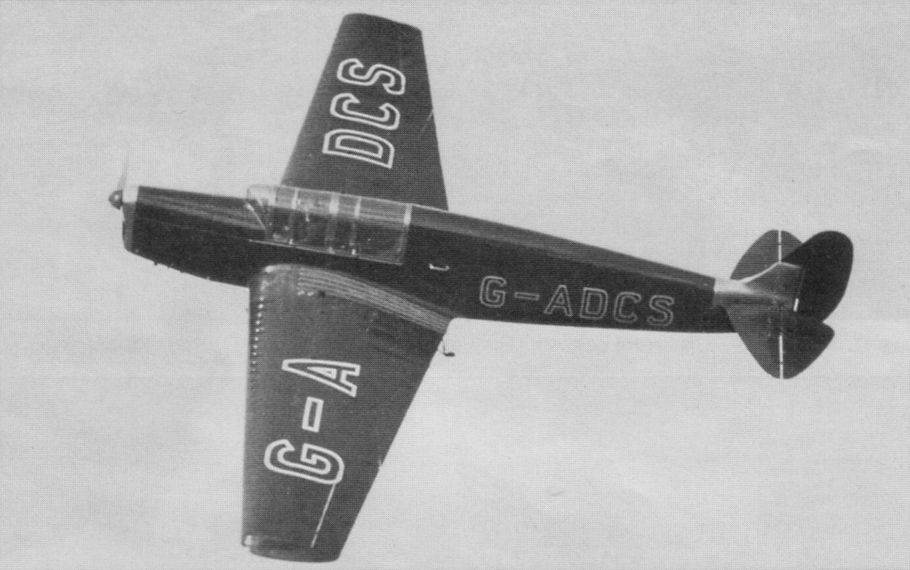
Регистрационный номер: G-ADCS [5] MB.1 в демонстрационном полете
-

Air Enthusiast 1995-09 / P.London - Martin-Baker's Aeroplanes
Регистрационный номер: G-ADCS [5] The Martin-patented system of tubular steel construction was first used in the single MB.1 seen here flying in the summer of 1935.
-

Air Enthusiast 1995-09 / P.London - Martin-Baker's Aeroplanes
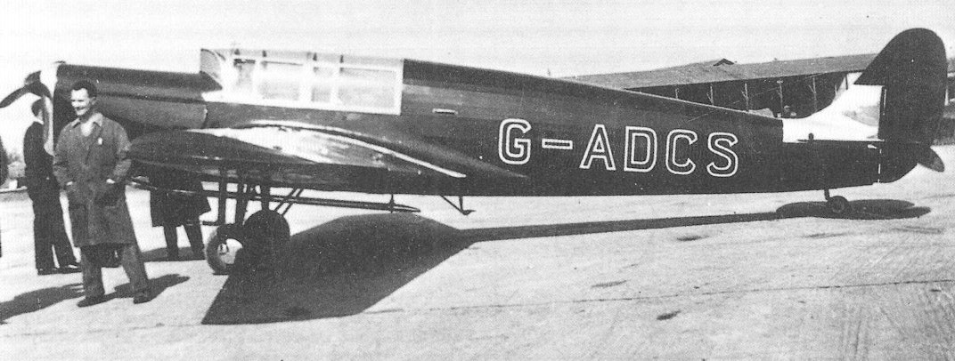
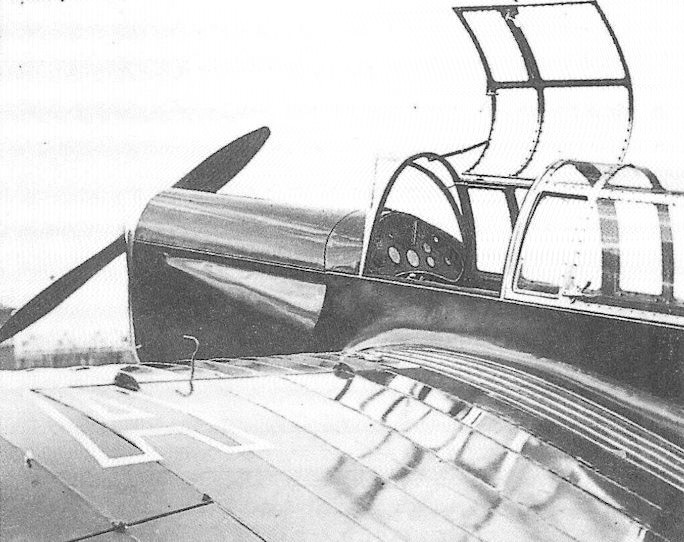
Регистрационный номер: G-ADCS [5] View showing well the ‘V’ windscreen in side view, the fin fillet, the long exhaust (later revised) and the rather stalky undercarriage.
-

Авиация и Космонавтика 2012-08 / В.Котельников - Истребители фирмы "Мартин-Бейкер" /Самолеты Второй Мировой войны/
Регистрационный номер: G-ADCS [5] -

Air Enthusiast 1995-09 / P.London - Martin-Baker's Aeroplanes
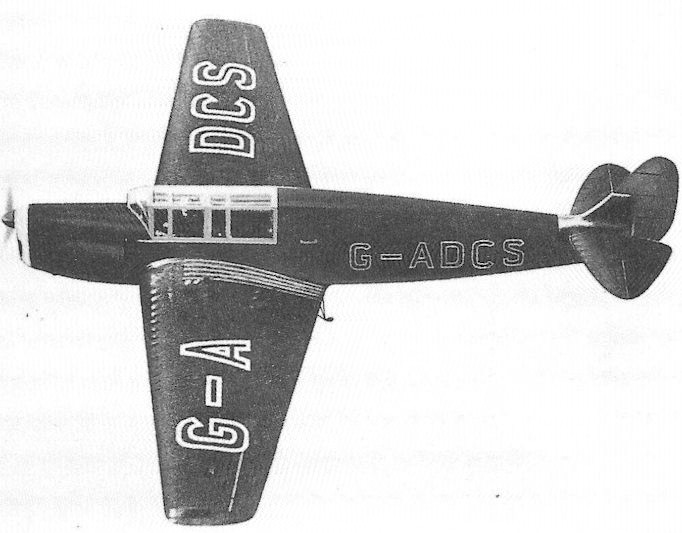
Регистрационный номер: G-ADCS [5] An indication of wing-fold geometry, cockpit hooding and tandem seating for two.
-

Flight 1934-12 / Flight
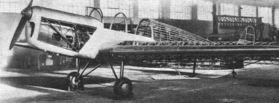
A three-quarter front view of the "MB1" in skeleton. Note the sharp "vee" of the windscreen.
-

Flight 1934-12 / Flight
A closer view of the "MB1" taken from behind, with the flap raised ready for folding the wing.
-

Flight 1934-12 / Flight
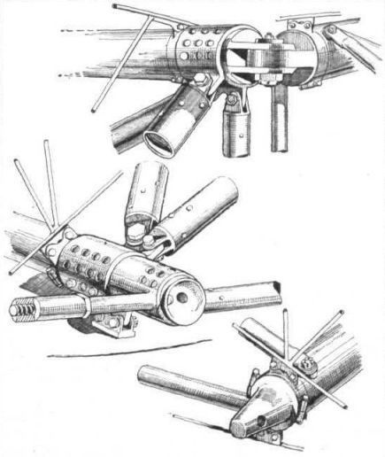
How the wing is released for folding: the front pin is of the screw type, and is withdrawn by rotating the small handle.
-

Flight 1934-12 / Flight
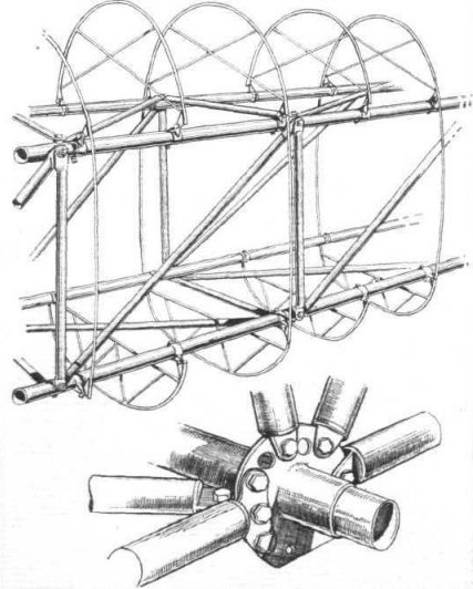
The wing spar consists of three large-diameter but thin-gauge booms, braced by smaller tubes, and converging towards one another at the other extremity.
-

Авиация и Космонавтика 2012-08 / В.Котельников - Истребители фирмы "Мартин-Бейкер" /Самолеты Второй Мировой войны/
Испытание лонжерона, собранного из труб
-

Air Enthusiast 1995-09 / P.London - Martin-Baker's Aeroplanes
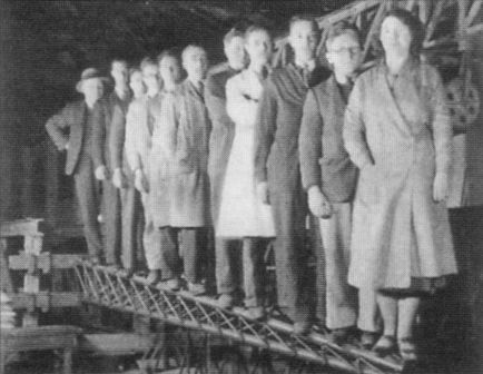
Before the fabric went on, Eric Stevens and Jim Clampitt show off the first applications of Martin’s structure in the MB.1. Its characteristics of ease in manufacture, high structural rigidity and the enormous benefits to be derived from design for maintenance and routine replenishment (armament for instance) cried out for an application more ambitious than a light aeroplane.
-

Flight 1934-12 / Flight
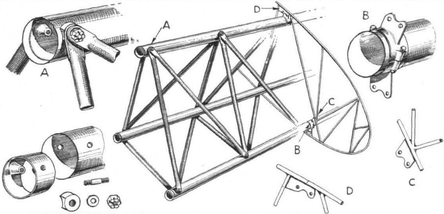
A set of sketches showing the chief points of interest in the wing spar. The details on the left are of the main strut attachment and on the right of the method by which the ribs are secured. The letters are a key to the details.
-

Flight 1934-12 / Flight
A section of the rear part of the fuselage, at which point the struts are secured in the same way as on the wing spar. At the bottom is one of the machined-fitting joints used in the front part of the fuselage.
-

Flight 1934-12 / Flight
(Top) The upper of the two joints about which the wing folds; (below) the two halves of the locking arrangement on the front joint of the wing spar. The screwed pin is worked by a small handle.
-

-

Flight 1934-12 / Flight
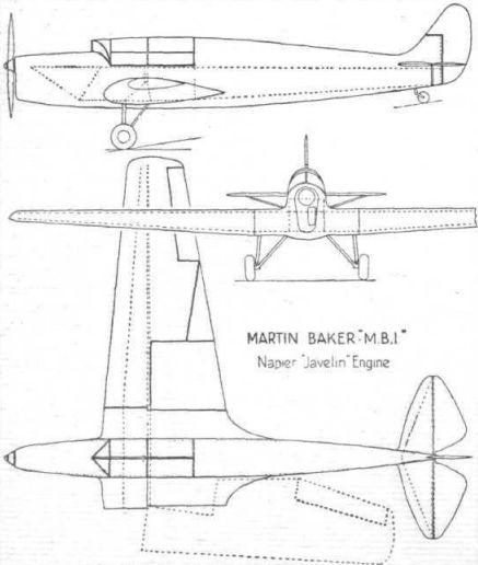
Martin-Baker "M.B.1" Napier "Javelin" Engine
-

Air Enthusiast 1995-09 / P.London - Martin-Baker's Aeroplanes
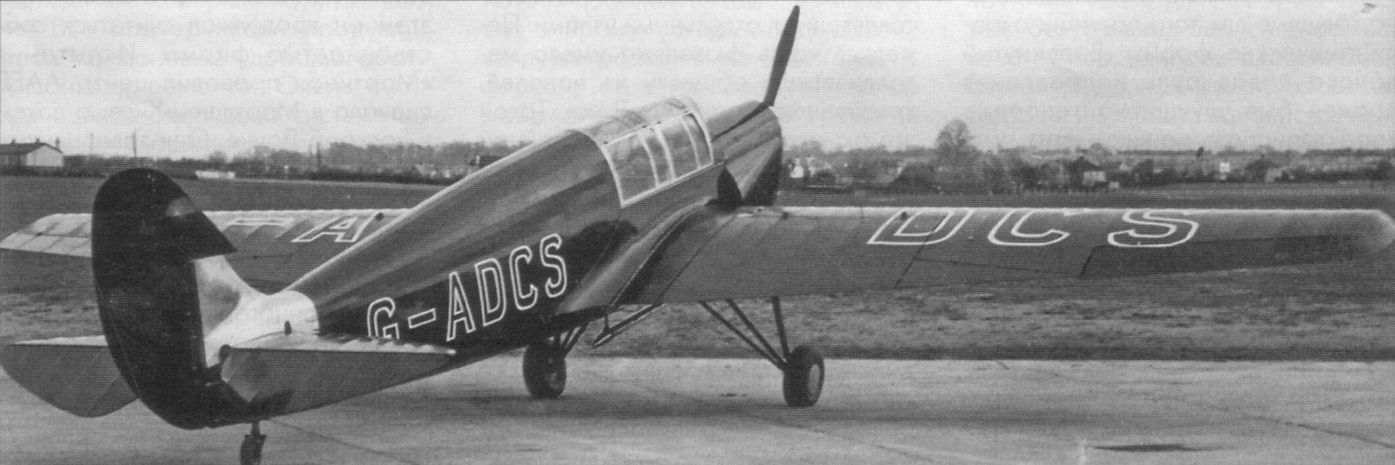
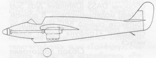
Martin-Baker MB.1.


- Фотографии