Vickers Type 54 Viking, Type 78 Vulture и Type 83 Vanellus
<...>
Viking VI, отличавшийся новой конструкцией крыла и двигателем Napier Lion, был переименован в Type 78 Vulture I. Вторая машина с 360-сильным (268 кВт) ПД Rolls-Royce Eagle IX получила обозначение Type 95 Vulture II, но позднее ее также оснастили двигателем Napier Lion. Эти два самолета использовались для неудачного кругосветного перелета в 1924 году под командованием сквадрон-лидера А.С. Макларена. Vulture II разбился в Бирме и был заменен запасным самолетом, доставленным из Токио. Но и он потерпел катастрофу 2 августа неподалеку от населенного пункта Никольский на дальневосточном побережье СССР.
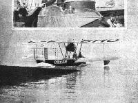
Последним в семействе Viking стал самолет, первоначально названный Viking VII, но позднее переименованный в Type 83 Vanellus. Единственная машина предназначалась для испытаний ВВС в качестве трехместного (пилот, стрелок-наблюдатель и стрелок) корректировщика для флота. Основным ее отличием от предшественника стало оперение, выполненное по схеме моноплана. Viking IV имел размах крыла 15,24 м и с двигателем Napier Lion развивал максимальную скорость 182 км/ч на уровне моря.
Показать полностьюShow all
Flight, March 1924
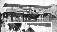
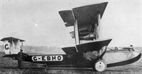
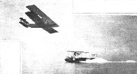
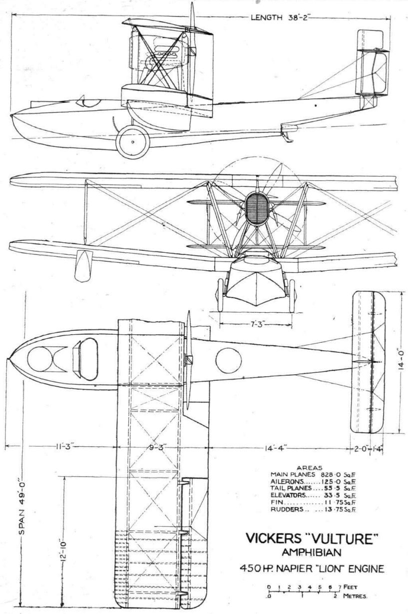
THE VICKERS "VULTURE" AMPHIBIAN
Napier "Lion" Engine
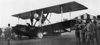
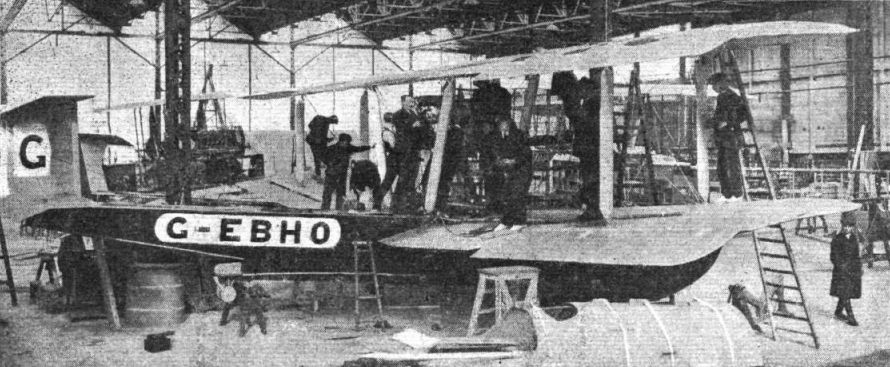
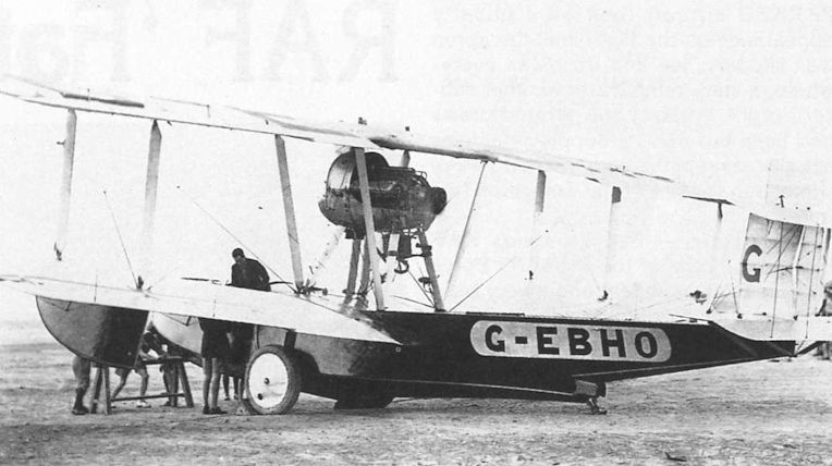
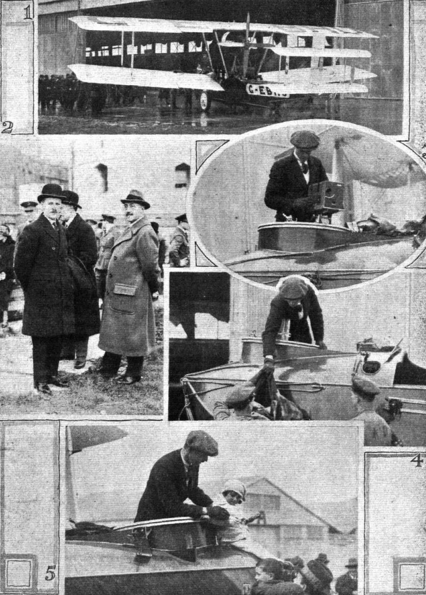
THE machine on which Squadron Leader MacLaren, Flying Officer Plenderleith, and Flight-Sergeant Andrews are to attempt the flight around the world is a Vickers "Vulture" amphibian flying boat with a Napier-Lion engine. Generally speaking the "Vulture" is similar to the "Vikings," and resembles the machine on which the late Sir Ross Smith was to have made the attempt in 1922. In the interim, however, certain changes in design have been effected, but these are chiefly in the nature of detailed improvements, and as a type the "Vulture" may be said to have descended from the "Viking" family. The type should be well known to readers of FLIGHT, as several "Vikings" have been described from time to time. Thus the "Viking IV" was described and illustrated in our issue of October 6, 1921, while the latest type of Vickers amphibian, the "Vanellus," was shown in a set of photographs published in our issue of February 14, 1924. As regards outward appearance, the "Vulture" differs from the "Viking IV" chiefly in being a single-bay instead of a two-bay biplane. This reduction in the number of struts has been made possible by using a thick wing section, No. 64, to be exact, which gives room for spars of very considerable depth. Furthermore, the chord has been increased from 7 ft. 1 in. to 9 ft. 3 ins., although the span has only been increased by 3 ft. (from 46 ft. to 49 ft.). The aspect ratio of the "Vulture" is therefore smaller than that of the "Viking IV," the figures being 5-29 and 6-49 respectively. The wing area has been increased by 243 sq. ft., from 585 sq. ft. to 828 sq. ft. As a matter of fact, one variation of the "Viking IV," built for Holland, had a slightly larger area than the standard type - i.e., 636 sq. ft., for a span of 50 ft.
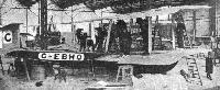
The Hull
The hull of the "Vulture" is very similar in its general lines to that of the "Vikings." The bottom is planked with a double skin of mahogany, the strakes of the two skins running at right angles to one another, and each forming an angle of approximately 45 degrees with the line of flight. The sides and deck are planked with "S.C.T." This is in the form of panels, something like three-ply, but with only two skins whose strakes run at right angles to one another. The skins are cemented together under pressure, and at considerable temperature. For the planing bottom this material could not well be used, as the steps have a considerable curvature, and sheet material cannot be bent to a double curvature. Thus the planing bottom differs from the sides in that, although it looks the same, its planks are applied individually, whereas the planking of the sides is applied in the sheet. The main frames are of mahogany, while the timbers and longitudinal stringers are of rock elm, through fastened to the planking.
The main step is open - i.e., the water is allowed free access to (and exit from) the space between the step planking and the bottom of the main hull. The rear step, however, is closed, and carries the tail skid and water rudders.
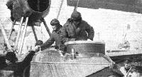
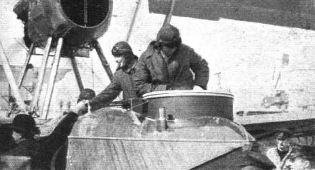
The Cockpits
Pilot and navigator are seated side by side in the main cockpit, the pilot on the starboard side. In front of him is a very complete instrument-board, with air speed indicator, altimeter, oil and petrol gauges, clock, compass, turn indicator, etc. We understand that with the exception of the Reid turn indicator all the instruments were supplied by Smith and Sons. The seat on the port side is placed in front of a small door giving access to the front compartment, which will be used mainly for photographic purposes. A cine-camera is carried, and when in use is mounted on a standard gun-ring, with provision for swinging it rapidly in any direction, ultimate fine adjustment, and locking device. In the bows of this compartment are lockers containing the photographic materials, plates, films, cameras, etc., and as the view from this cockpit is particularly unobstructed the expedition should secure some very fine pictures, "still" and "moving." A fairly large cockpit aft of the wings will be used for housing the spares, of which a considerable quantity are carried. Among these may be mentioned a four-bladed propeller, which, to economise space, is made in the form of two separate two-bladers with thin bosses, which can be secured on the propeller shaft at right angles to one another.
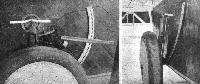
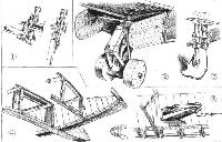
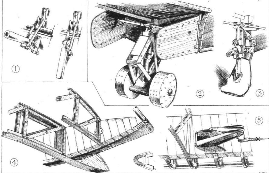
The Engine Mounting
The Napier "Lion" engine is mounted on steel tube struts rising from the hull, the engine supports being independent of the wing structure. Great care has been taken to make the engine as accessible as possible, and to this end the cowling has been made in several sections, held in place by quick release devices of the type shown in one of our sketches. By removing the appropriate panel of the cowling any part of the engine can be reached with a minimum of delay, a matter of considerable importance on an expedition like that planned. A nose radiator with shutters forms the front portion of the engine nacelle, and slung underneath is a small oil radiator of novel design, developed by Mr. Rex Pierson, chief designer of Vickers Aviation Works. This oil cooler consists of circular section copper top and bottom tubes connected by streamline section vertical tubes. A spring-loaded valve in the top tube allows the oil to be pumped through a bye-pass when the pressure exceeds a certain amount. Thus when starting up in the morning, with the oil quite cold and thick, it would be impossible to force it through the streamline tubes; the valve then opens and allows the oil to pass through the horizontal tubes until the oil has become sufficiently thin to pass through the vertical streamline tubes. That this type of oil cooler is effective will be realised when it is recorded that a temperature drop of no less than 16 degrees has been obtained by fitting the cooler.
While on the subject of the engine installation, it should be mentioned that the two large main tanks are carried in the hull, whence petrol is forced to a gravity tank in the top centre-section by two windmill-driven pumps. A hand pump is fitted in the pilot's cockpit. For the long overseas flights an extra tank will be fitted in the cockpit. Extra oil and water tanks are fitted in the bilge, to be pumped into the service tanks as required. The total petrol capacity of the tanks is: 321 gallons in the two main tanks and 80 gallons in the extra tank, giving a total of 401 gallons. Cruising at a little over 80 miles per hour, the machine probably does something like 4 miles per gallon, so that the range, in still air, should be in the neighbourhood of 1,600 miles. As a matter of fact, as the fuel is used up and the machine gets lighter, it will in all probability do more, and under favourable conditions should be capable of the non-stop flight from St. John's to Ireland. If conditions are not favourable for the direct flight the route via the Azores will be followed.
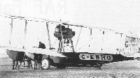
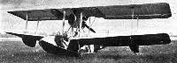
The Retractable Undercarriage
One of the special features of the "Vikings" has always been the retractable undercarriage, whose wheels move forward and up, following quadrants on the sides of the hull, until clear of the water. In the "Vulture" the same principle has been followed, but an oleo undercarriage has been substituted for the rubber shock absorbing gear of the "Vikings." By working at high pressure (about 800 lbs./sq. in.) it has been possible to bring the weight down to the same as that of the rubber chassis. In fact, the oleo undercarriage is actually a little lighter, by something like 3 lbs. per side. The principle of the Vickers oleo gear, which is used on a number of Vickers types, is that a plunger or piston of slightly conical shape works inside a tapered bore cylinder. When the piston, and the oil above it, is at the bottom of its stroke it exactly fits the cylinder. As it moves up it leaves, owing to the taper, a small annular space around the piston, through which some of the oil passes to the space below the piston. The taper is so proportioned as to give a constant pressure.
Working at such high pressures, it was found that the ordinary type of pump was scarcely equal to the job, and consequently Mr. Pierson evolved a special two-stage pump, which raises the pressure to the required figure with apparently little effort. This pump is shown in place on the starboard undercarriage in one of our photographs. It is held on by clips, and is quickly transferred from one side to the other. The oleo undercarriage makes a very "clean" gear, as will be seen from one of our photographs, and as the weight is the same it should be more suitable for this particular flight than the rubber gear with its need for renewal at fairly frequent intervals.
The tail skid of the "Vulture" is slightly different from that of the "Vikings," and does not form a water rudder. For wheeling the machine about on the ground or in a shed a light two-wheeled tail trolley of Vickers Duralumin is fitted. This trolley is shown in place on the skid in one of our sketches. The framework aft of the skid serves as a fulcrum for a jack. When the tail has been raised sufficiently to allow the wheel axle to be pushed through the skid, the two wheels are easily mounted and secured by wing-nuts. Thus the crew should be able to wheel the machine about without outside assistance. This would scarcely be possible without the tail trolley, as there is a very considerable weight on the tail skid when the machine is standing on the ground. Instead of making the tail skid perform the function of a water rudder, as on the "Vikings," two separate water rudders are fitted at the rear step. These rudders are not parallel with one another, but are so placed as to be in line with the sides of the hull just forward of the step when the rudder is central. This arrangement has presumably been chosen in order to reduce the rudder drag. It goes without saying that both the tail skid and the water rudders are connected up to the air rudders so as to enable the machine to be steered on the ground or water, as the case may be.
The Wings
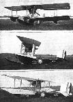
As already mentioned, the wings of the "Vulture" are in the form of a single-bay biplane. The centre-section struts, it will be seen, are. raked outwards considerably so as to reduce the free length of spar in the top plane. The main wing spars are of box section, with spruce flanges and three-ply sides, the whole wound with doped fabric. The ribs are of lattice type, with double lattice bars of spruce, riveted to the top and bottom members with Duralumin rivets. The construction is simple, light and very strong. The ailerons are carried on brackets in the form of continuations aft of the rear spar of certain wing ribs of specially strong construction. The loads which ailerons of this type may throw on the brackets are very large, but by having the hinge ribs running through, sufficient strength is provided. The strength of this part of the structure is probably very greatly increased by the semi-circular section three-ply which covers the face of the rear spar, as the three-ply fits into the webs of the hinge-brackets. The details are shown in a sketch. This three-ply probably relieves the rib flanges of most of the shear. The aileron cables are carried inside the wings, and by using a bracket and crank, as shown in one of our sketches, it has been possible to use tie-rods throughout and to do away with all cables passing over pulleys.
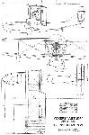
The main dimensions of the Vickers "Vulture" are shown on the general arrangement drawings. The airworthiness weight of the machine is 6,000 lbs., giving a wing loading of 7-25 lbs./sq. ft., which is fairly light for a flying boat, especially in view of the fact that 64 is a fairly high-lift section. The landing speed should not be more than about 45 m.p.h. The top speed with full load and at sea level is about 104 m.p.h., and the climb to 5,000 ft. occupies nine minutes. The cruising speed, as already mentioned, is about. 82 m.p.h. The fact that the Vickers "Vulture" is an amphibian should render it particularly suitable for the flight, as there must necessarily be many occasions when the ability to alight on or get off from land or water equally well, means the difference between success and failure. As all Vickers machines, the "Vulture" is beautifully finished, and no effort has been spared to make the construction as sound as is humanly possible. The fact that the flight is a private venture, in which the machine is supplied by Vickers, Ltd., the engines (two of which have been sent to Toronto and Tokio respectively) by D. Napier and Son, and the petrol supplies by Shell, as against the American Army official attempt, makes the effort all the more creditable, and we are sure all our readers will join us in wishing Squadron-Leader MacLaren, Lieut. Plenderleith and Sergeant Andrews every possible success.
Показать полностьюShow all