
Flight, November 1925
THE POWELL LIGHT 'PLANE
A Successful American Machine with Bristol "Cherub" Engine
As already recorded in FLIGHT, the machine which won all the prizes in its class at the New York air races this autumn was the Powell light biplane, fitted with the Bristol "Cherub" engine. This machine won the Aero Digest Trophy, the Scientific American Trophy, and the Dayton Daily News Trophy, as well as prize money totalling $2,000. The machine was designed, and to a large extent built, by Prof. C. H. Powell, Professor of Aeronautics at the University of Detroit, and formerly of the National Physical Laboratory at Teddington. All the design work was carried out by Prof. Powell, and the machine was built by him, with the assistance of Mr. P. Altaian and the occasional help of others.
Prof. Powell has been good enough to send to FLIGHT a set of blue prints and photographs of his interesting machine, and certain technical data upon which the following description is based. Prof. Powell states that the machine was designed "to win at all costs, which it did at considerable cost," and it may be mentioned that Prof. Powell himself bore the cost of construction and materials, as well as all the expenses incidental to the races. The machine can therefore justly be regarded as purely an amateur effort, and as such is, it will be agreed, very creditable indeed.
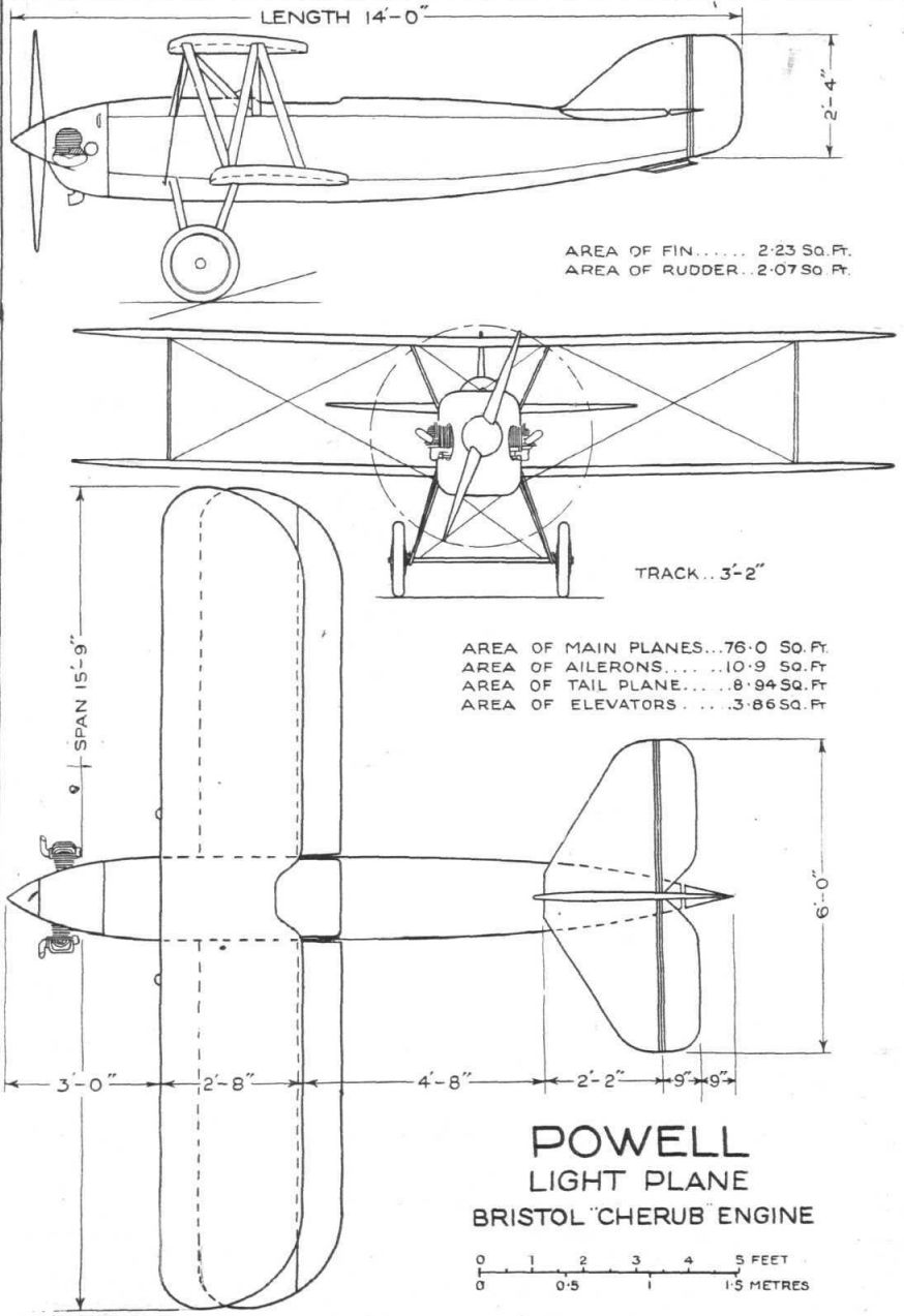
In the design of the Powell light 'plane the biplane type of wings was probably chosen for lightness and compactness. The wing structure is of orthodox design aerodynamically, but considerable scheming must have been required to get the wing fittings for the streamline wires buried inside the wings, since with the thin section used (R.A.F. 15) the rear spar had depth of but 1 3/4 in. These fittings are in the form of forked plates or stirrups, the supports for which are so arranged as to allow the wire to swing in all directions, thus ensuring a direct pull without bending at the threads. The top plane is built in one piece, the dihedral being built in, as it were. Owing to the short span (15 ft. 9 in.) it was possible to build the spars in one piece without splicing.
The fuselage is a ply-wood covered monocoque structure, built on 3/8 in. ply-wood formers. The three-ply covering itself is rather thick (3/16 in.), and Prof. Powell states that, although a good deal of weight could have been saved by the use of thinner ply-wood for the covering, the construction is very robust. The fuselage has been designed with a view to reducing head resistance to a minimum, this being important because the pilot's body is the largest single item and the comparatively large fuselage area forming a considerable proportion of the total resistance. In other words, Prof. Powell was restricted, by the size of his pilot, in the reduction of S, and consequently did all he could to reduce K in the fundamental formula R = KSV^2, of which British designers were reminded by Mr. Fairey recently. The fuselage certainly appears to be of good shape, and the machine is altogether curiously reminiscent of the Curtiss racers, although the "hump" in the nose is below instead of on top.
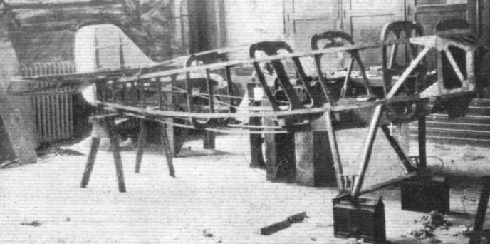
In the construction of the fuselage use was made of jigs for the support of the formers or bulkheads while the covering was put on. Prof. Powell states that, although the making of the jigs took considerable time, they well repaid the work subsequently. A jig was also used in building up the undercarriage, in the construction of which welding was employed.
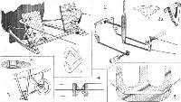
One of the problems encountered was the seating accommodation for the pilot. The seat had to be about two inches from the bottom of the floor, and three push rods in the control unit had to pass under it and still have clearance for working. Two of the accompanying photographs show this part of the fuselage while still in the skeleton stage, and it will be seen that little space is wasted. The controls are shown in a diagrammatic perspective sketch, and are of somewhat unusual form. Ailerons are fitted to the bottom plane only, and are operated by torque tubes as shown. The rudder is operated by pedals in place of the more usual rudder bar, partly in order to get a more delicate rudder control, and probably also because of the narrow width available in the forward portion of the fuselage. Many of the metal fittings are of the sheet steel type, this having been chosen because all the welding work had to be sent out, and it was therefore desired to keep this down to a minimum.
The Bristol "Cherub" engine is mounted on a steel plate mounting in the shape of a truncated pyramid. This mounting may be seen in the photograph of the fuselage in skeleton. Professor Powell states that the mounting is rather heavy, but that this was considered necessary in order to guard against the torque-reaction of the two-cylinder opposed engine. Apart from torque variation, he states, the engine is almost perfectly balanced, and at 3,200 r.p.m. runs very smoothly. A petrol tank of 8 gallons capacity is normally fitted under the deck fairing, but for the New York races a small tank, of 2 1/2 gallons capacity, was fitted and actually made on the field.
The undercarriage is of normal V-type, built up of streamline steel tubes, welding being employed for joining at the angle of the struts. The axle is of the divided type, the two short halves resting in a metal trough or channel running across from side to side. This channel is streamlined with wood fairings, and an unusual feature is that the usual/wires from the axle hinges to the fuselage are absent, the strength of the trough being sufficient to withstand bending without the aid of bracing.
Three-ply wood enters largely into the construction of the tail surfaces, and a very unusual feature is formed by the leather hinges employed for the rudder and elevator. These hinges are in the form of continuous strips of leather, arranged as shown in section in Fig. 4 of our set of sketches. For the rest the Powell light 'plane is of normal construction, and the only other feature to which attention should be called is the almost ridiculously small size of the machine. The photograph and scale drawings do not really convey an impression of the size, any more than will, to the average person, the statement that the span is but 15 ft. 9 in. and the length 15 ft. What these dimensions actually mean is that the machine could stand comfortably in a fairly small living room, and that thus the question of garaging is a simple one. The wing area is but 76 sq. ft. including ailerons, or roughly half of the average area of the Lympne single-seaters of 1923. Thus, the Powell light 'plane is certainly one of the smallest practical aeroplanes hitherto produced.
The dimensions and areas of the Powell light 'plane are shown on the general arrangement drawings. Following are the figures for weight, etc.: Weight of machine empty, 310 lbs.; fuel and oil (2 1/2 gallons), 15 lbs.; crew, 150 lbs.; total loaded weight, 475 lbs. Fuel capacity (small tank), 2 1/2 gallons; large tank, 8 gallons, endurance (large tank), 6 hours; range (large tank), 400 miles. Wing loading, 6-2 lbs./sq. ft.; power loading, 15-8 lbs./h.p. (on 30 b.h.p.). Top speed, 85 m.p.h. Landing speed, 50 m.p.h. Climb to 5,000 ft. in 17 minutes, to 10,000 ft. in 45 minutes. Ceiling, 15,000 ft. These figures, it should be pointed out, relate to the machine as fitted with the small tank.
- Flight, November 1925
THE POWELL LIGHT 'PLANE
Фотографии
-
Flight 1925-12 / Flight
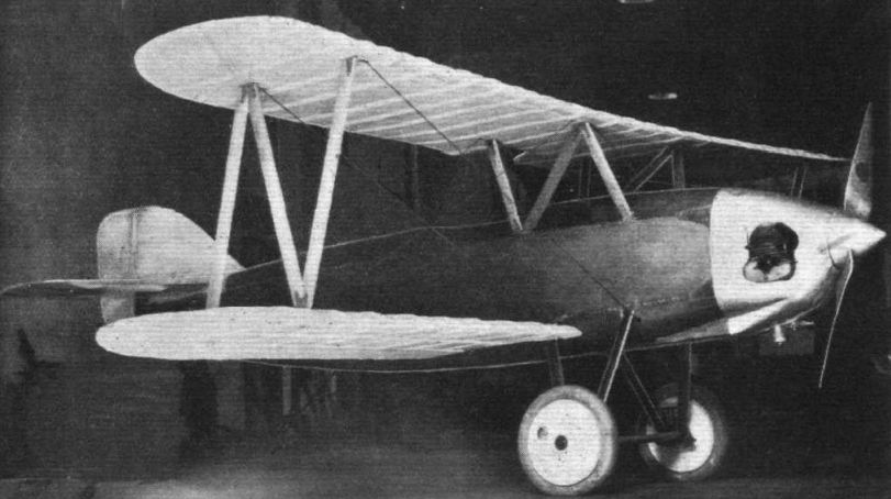
THE POWELL LIGHT 'PLANE: Three-quarter front view. Note the neat cowling around the Bristol "Cherub" engine. The fuselage is covered with ply-wood.
-

Flight 1925-12 / Flight
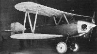
The Powell Light 'Plane: View of the skeleton framework of the fuselage. The undercarriage V's are made of streamline steel tubes.
-
Flight 1925-12 / Flight
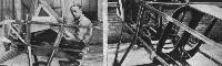
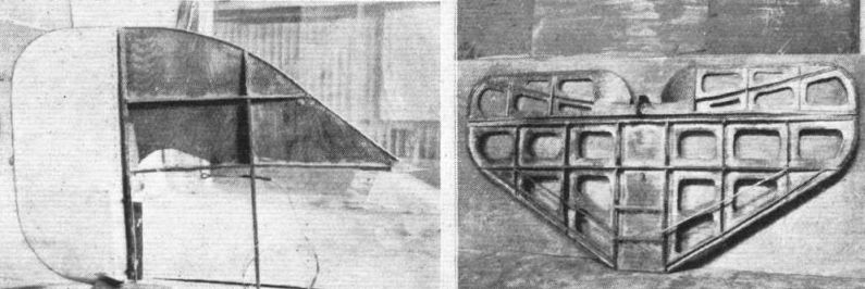
THE POWELL LIGHT 'PLANE: On the left the front portion of the fuselage. The man in the cockpit gives a good idea of the small size of the machine. On the right another view of the pilot's cockpit, showing controls, undercarriage struts, bulkheads, etc.
-
Flight 1925-12 / Flight
THE POWELL LIGHT 'PLANE: Three-ply wood enters largely into the construction of the tail.
-
Flight 1925-12 / Flight
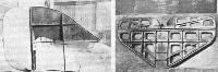
THE POWELL LIGHT 'PLANE: Some constructional features. 1. The rudder pedals which take the place of the more usual foot bar. 1a shows the sheet metal footguards to which the rudder control wires are attached. 2 is a diagrammatic perspective sketch of the elevator and aileron controls, while 2a shows, in the flat and after bending, one of the bell cranks of the aileron control. In 3 and 3a are shown the undercarriage with divided axle. The cross-member is in the form of a channel or trough-section metal strut in which the axles are housed, and which is streamlined with wood fairings. 4 shows the leather hinge used in elevator and rudder, while 5 is a bulkhead with lift wire attachments.
-

Flight 1925-12 / Flight
Powell Light Plane Bristol "Cherub" Engine


- Фотографии