

Описание
Страна : Австрия
Год : 1935
Вертолет (проект)
Flight, August 1939
REAL HELICOPTER PROGRESS
Spectacular Performance of the Asboth Designs : Machine to be Built in England
By THE EDITOR
FOR many years Flight has followed with interest the work of the Hungarian aeronautical engineer Oscar von Asboth, who has long been associated with helicopter research, and who as early as 1918 built a three engined captive helicopter which ascended on several occasions and during one flight reached a height ot 50 metres (about 160 ft.). Political and financial circumstances have hindered and delayed Mr. von Asboth’s research but have not succeeded in stopping it. He has never ceased to work away at his chosen task. Sometimes he has had to work alone, but from time to time he has been able to get together sufficient money by Government grants to run a drawing office, and at such time the rate of progress has, naturally, been greater.
The history of Oscar von Asboth’s career and experiences would make fascinating reading, but space considerations forbid, even were it advisable, to give to the world the story of the obstacles he has met and the intrigues which have sought to put a spoke in his wheel. For the moment we are concerned only with the technical aspect of von Asboth’s work, and with the degree of perfection which has crowned his many years of unremitting labour.
Performance, in the form of horizontal speed, is of no great importance in helicopter operation. If it is there, so much the better. But the ability to ascend and descend vertically, and to hover indefinitely, is a quality not shared by the fixed-wing aeroplane, so that a small loss in maximum horizontal speed is not a high price to pay for it. That the helicopter need not necessarily be hopelessly outclassed in horizontal speed seems to be indicated by the calculations made by Mr. von Asboth for a machine of up to 4,800 lb. gross weight, fitted with a supercharged engine developing 580 h.p. at 12,000 ft. At that gross weight the maximum speed should be 185 m.p.h., and if the gross weight were reduced to 4,000 lb. the speed should be just over 200 m.p.h. These estimates are based on actual results obtained during extensive wind tunnel tests with the best of the types of rotor tried. Mr. von Asboth does not regard this as necessarily the best obtainable, but it is the best that can be expected, using existing design features.
The particular design on which this estimate is based is known as the type A.H.X. The tare weight is 1,300 kg. (2,860 lb.), and calculations have been made for disposable loads of 500 kg. (1,100 lb.), 700 kg. (1,540 lb.), and 900 kg. (1980 lb.). As one of the graphs shows, the rate of climb is extraordinarily high (for instance. the first 3,000 ft. takes only about two minutes at the greatest gross weight, 4,840 lb.), and is maintained up to considerable heights. The absolute ceiling is 5,800 metres (19,000 ft.) with the engine mentioned above.
Autorotation is. of course, an essential feature of any helicopter design. If this is not present, the machine will fall like a stone when the engine stops. In the Asboth designs autorotation is ensured automatically and instantaneously; how this is done we are not permitted to explain at the present time, but we have seen the drawings and there is no doubt that the change in incidence which is necessary for autorotation to take place is ensured.
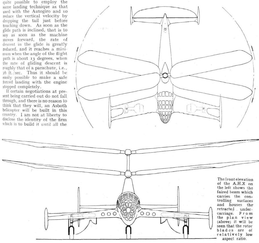
Another graph shows the different rates of descent obtained at different angles of the flight path. As was to be expected, this rate is highest when the angle of the glide path is greatest, viz., when the machine is descending vertically. At the maximum gross weight it is in the region of 41 ft./sec. But it is, of course, quite possible to employ the same landing technique as that used with the Autogiro and so reduce the vertical velocity by dropping the tail just before touching down. As soon as the glide path is inclined, that is to say as soon as the machine moves forward, the rate of descent in the glide is greatly reduced, and it reaches a minimum when the angle of the flight path is about 13 degrees, when the rate of gliding descent is roughly that of a parachute, i.e., 16 ft./sec. Thus it should be easily possible to make a safe forced landing with the engine stopped completely.
If certain negotiations at present being carried out do not fall through, and there is no reason to think that they will, an Asboth helicopter will be built in this country. I am not at liberty to disclose the identity of the firm which is to build it until all the parties concerned have signed on the dotted line. That may happen at any moment.
The machine which is to be built in this country is a variation of the Asboth type AH.6. The engine to be fitted will probably be a Gipsy Six II of 200 h.p., and the following data have been calculated for it: Rotor diameter, 33.5 ft.; area or rotor disc, 1,023 sq ft.; weight empty, 1,763 lb.; disposable load, 385 lb.; loaded weight, 2,148 lb.; lift (calculated on previous rotors) 3,260 lb.; excess of lift 1,100 lb.; rotor efficiency (calculated according to the Bendemann formula) 0.85; rotor disc loading (autorotation), 2 Ib./sq. ft.; rotor disc loading (at greatest power-driven lift), 3 lb./sq. ft.; power loading 11 lb. /h.p.; maximum initial thrust, 1.540 lb.; maximum horizontal speed, 107 m.p.h. ; ceiling 11,500 ft. ; initial rate of climb, 1,760 ft./min. ; 3,300 ft. in 2 mins; 6,600 ft. in 5 mins.; 10,000 ft. in 9 mins. 40 secs.; 11,500 ft. in 18 mins.; minimum rate of descent (autorotation) 14 ft./sec. Lift coefficient by autorotation 1.5.
These figures indicate that Mr. von Asboth has progressed a very long way towards a helicopter with a really practical performance. How he has attained this achievement may not be explained in detail at the moment. I have, however, had the privilege of examining his drawings, and the so-called four-function hub which he has designed is neither complicated nor difficult to manufacture. In outline it may be said that the blades are set rigidly on the hub at an angle to the horizontal plane. That is to say, they have no flapping hinges. The angle is such that it represents the resultant between centrifugal force and lift when the machine is hovering, i.e., when there is no forward speed. Under other conditions there is a residual torque moment, but this is not of great magnitude and is taken care of in the design of the hub.
A Four-function Hub
As the name implies, the Asboth four-function hub performs four duties, three of which are entirely automatic while the fourth is represented by the pilot’s manually-operated control. The oppositely rotating rotors tilt out of the horizontal plane when the machine moves forward, but as the lower can be regarded as the mirror image of the upper rotor, balance is maintained. The angle of incidence is automatically changed to give autorotation the instant the engine speed is reduced. And the hub automatically compensates for sudden changes of the relative wind, such as will be caused by gusts, for example. The pilot's control tilts the planes of the rotors and thus causes the machine to hover or move forwards.
When we are in a position to publish the drawings it will be seen that the Asboth four-function hub is probably the simplest and smallest ever designed so far.
Although the four-function hub is an extremely important part of the Asboth design, it would not by itself give the remarkably high performance which calculations have indicated to be attainable. The secret of this is to be found in the aerodynamic design of the rotor blades. As a result of his long years of research, experiment and mathematical investigations (the latter of which were discussed in great detail with the late Mr. Glauert of the Royal Aircraft Establishment), Mr. von Asboth has come to the conclusion that the type of rotor in which the blade incidence is constant along the span does not and cannot give maximum lift because the lift distribution along the blade is wrong. He claims that an efficiency of only about 0.55 or 0.60, calculated according to the Bendemann formula, 'is possible, whereas with his design of blade efficiencies as high as 0.85 have been proved attainable.
The drawings of the A.H.X. published herewith give some slight hint of the Asboth blade design. It will be noticed that the aspect ratio is relatively low, a fact which should help to reduce rotor weight, since the large blade chord results in room for a deeper spar. But that is by no means the real secret. What in effect Mr. von Asboth has done is to use a blade which is a variation of the familiar airscrew blade, with an inner portion normally set at no angle of incidence, a middle portion set at a small positive angle, and a tip portion set at a negative angle.
Lift is, of course, derived mainly from that portion which is set at a positive angle of incidence. As it is situated fairly far out from the hub, it is travelling fast and thus giving a high lift. The extreme tip contributes little or nothing to the lift, but when autorotation sets in, the negative angle of the tip gives a very powerful torque and maintains autorotation even under conditions in which the constant-angle type of rotor would stop, or at least slow down to a dangerous extent.
Excellent Autorotation
Mr. von Asboth has tested numerous blade forms in a wind tunnel specially constructed for rotor tests. Finality has certainly not been reached, and the already excellent autorotation can be further improved. An important feature of the Asboth rotor system is that rotor speed, and, therefore, lift, increases with sinking speed, so that it is impossible for the machine to "fall out of the air."
The drawings published herewith show the A.H.X type of Asboth helicopter. They are in the main self-explanatory, but it might be pointed out that the wing-like structure in front is merely a streamlined beam for carrying the control surfaces. At the same time it houses the retracted undercarriage. The A.H.6 will, it may be assumed, be of similar appearance. The engine is placed centrally m fuselage, and a fan will be used for cooling when machine is ascending vertically or hovering.
- Flight, August 1939
REAL HELICOPTER PROGRESS
Фотографии
-

Flight 1935-03 / Flight
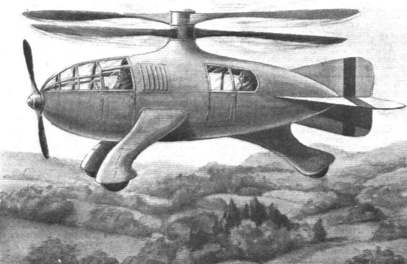
A Flight artist's impression of the Asboth helicopter, drawn from plans of the Hungarian inventor. The two sets of rotor blades revolve in opposite directions, thus cancelling out torque reaction.
-

Flight 1935-05 / Flight
VISION OF THE NOT-SO-DISTANT FUTURE? In Flight of March 21 there appeared an artist's impression, drawn from the inventor's plans, of the Asboth helicopter. Here is another sketch, made from revised designs. The engine-driven rotors for vertical lift revolve in opposite directions, thus cancelling out torque reaction. The original experimental machine has many hours of efficient flying to its credit.
-

Flight 1939-08 / Flight
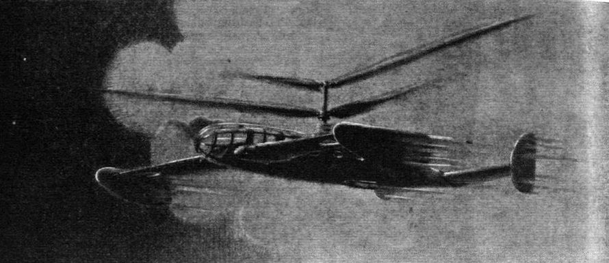
An artist’s somewhat impressionistic idea of how the Asboth helicopter will appear in flight.
-

Flight 1939-08 / Flight
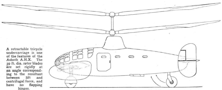
A retractable tricycle undercarriage is one of the features of the Asboth A.H.X. The 39 ft. dia. rotor blades are set rigidly at an angle corresponding to the resultant between lift and centrifugal force, and have no flapping hinges.
-

Flight 1939-08 / Flight
The front elevation of the A.H.X on the left shows the faired beam which carries the controlling surfaces and houses the retracted undercarriage. From the plan view (above) it will be seen that the rotor blades are of relatively low aspect ratio.
- Фотографии