
Варианты
- C.W. Aircraft - Cygnet - 1937 - Великобритания
- General Aircraft - Cygnet II / GAL.42 - 1939 - Великобритания
- General Aircraft - Owlet / GAL.45 - 1940 - Великобритания
Flight, December 1936
A "MINOR" in METAL
Initial Effort by a New Concern: First Details of the C-W Cygnet Minor: Stressed-skin Construction: A Projected "Twin"
STRESSED-SKIN metal construction is no longer the expensive peculiarity of high-powered transports and military types; there is a definite trend, particularly in America, toward light “private-owner” models built on this system. We may count ourselves fortunate that a few enterprising souls have had the foresight to study the possibilities of stressed-metal covering as applied to the smaller types, and among these Messrs. C. K. Chronander and J. I. Waddington, partners in C-W Aircraft, whose works are in Montrose Avenue on the Slough Trading Estate, are deserving of special commendation for producing Great Britain's first completely metal-covered light aeroplane.
As C-W Aircraft is a title not previously met with by readers, let us explain that policy is directed by Messrs. Chronander and Waddington, and that Mr. J. A. Heron is the chief engineer. These three are quite conversant with the most recent practice in stressed-skin construction, and hope to have the Cygnet flying in January. They are talking of delivery of production machines by Easter.
The Cygnet Minor ("Major" when any of the "Major" engines, such as Gipsy Major, Cirrus Major, Villiers-Hay Maya or Menasco Pirate are fitted) has been planned as a two-seater side-by-side machine for private operation or club training. A second passenger may be accommodated if the fuel load is reduced from 20 gallons to 8 gallons. The machine is fully aerobatic.
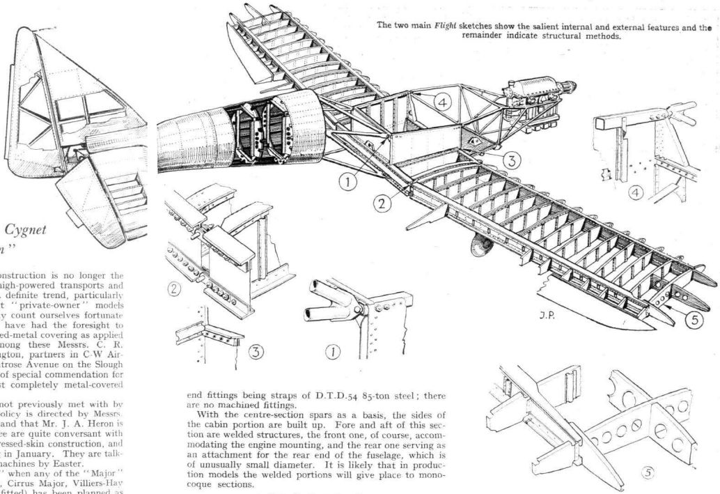
The low, cantilever wing has two main spars with booms of R.R. 56 alloy and light diaphragm ribs stiffened up with members of "bowler-hat" section. Torsional and shear leads are taken by the duralumin skin covering, but bending loads are taken by the spars. It is claimed that the wing, including ailerons, flaps and controls, weighs only 2 lb. per square foot. It is constructed in three sections: two outer panels and a centre section of seven-foot span and twenty-inch depth, which houses the fuel tanks. The comparative shallowness of this portion facilitates entry to the cabin. Attachment to the fuselage is effected by four bolts, the root-end fittings being straps of D.T.D.54 85-ton steel; there are no machined fittings.
With the centre-section spars as a basis, the sides of the cabin portion are built up. Fore and aft of this section are welded structures, the front one, of course, accommodating the engine mounting, and the rear one serving as an attachment for the rear end of the fuselage, which is of unusually small diameter. It is likely that in production models the welded portions will give place to monocoque sections.
A "Tadpole" Fuselage
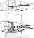
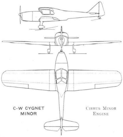
Stringers of Z section and built-up frames feature in the after portion of the fuselage, to the rear end of which the tail unit is attached by eight bolts. The small cross-section of the rear part of the fuselage is said to confer aerodynamic and structural benefits, and merges with the wings through the medium of fillets of unorthodox design, the shape of which is seen to advantage in the accompanying drawings. This means that both in plan form and side elevation there is a very pronounced “slimming off.”
All control surfaces are metal-covered and of quite surprising lightness; the elevator weighs 3 1/2 lb., and the rudder 4 1/2 lb. The basic structure of the one-piece tailplane is similar to that of the wing.
The construction of the monocoque portions and the skinning of the wings has been simplified by the use of pop rivets and the employment of a special adaptation of a standard type of a riveting gun, which, it is claimed, enables the riveting to be done 20 per cent, faster than by normal methods. Countersinking features on the leading edges of wing and tailplane.
For riveting the skin on to members which cannot be drilled completely through a drill has been devised to make an "undercut" hole in the solid metal, enabling a pop rivet to be inserted and the head to be formed inside the undercut. A pantograph device has been developed (for the satisfaction of inspectors) which shows, four times actual size, the contours of the hole.
Flaps of high aspect ratio are incorporated having 24-gauge skin with triangulated ribs of light channel section. Operation is through a torque tube by a manual control with a spring servo device which automatically pulls down the flaps to 15 degrees for take-off. This spring bias also helps to keep the flaps closed in normal flight. The maximum depression is 60 degrees, permitting, it is estimated, a landing speed of 35 m.p.h.
Single-strut Undercarriage
A 6 1/2 in. travel is provided for in the Dowty single-strut undercarriage. The legs are carried in welded steel sockets attached to the front spars. The brakes are of the differentially operated Bendix type.
A single central column between the occupants and twin sets of rudder pedals permit dual control, although for specialised training work the manufacturers visualise two complete sets of controls.
Bias on fore-and-aft trim is effected by a spring in the elevator circuit, one end of which can be moved on either side of a fulcrum so that plus or minus or zero bias can be obtained at will by the operation of a tell-tale knob on the control column. The aileron and elevator controls travel in conduits in the centre of the cabin, lids being provided for inspection.
The two sets of rudder pedals are linked with a parallel motion, so that only the pedals are normally visible. One set can be removed in a few seconds, leaving the passenger's space free from excrescences.
Production Cygnets will be upholstered by Rumbold in any colour or style desired. Doubtless, Mr. Rumbold will find his task of soundproofing considerably simplified by the absence of flat panels. Rhodoid panels of quite unusually large proportions, coupled with the good location of the seats in relation to the wing, should benefit outlook.
Accommodation
The seats are fully adjustable for height and leg-length. Smith's instruments are grouped on the centre and left of the facia board, where they are visible to pilot and passenger. To the left is a capacious locker and map tray. A patented design of exit, hinged about the front side members of the cabin enclosure, is incorporated.
The windscreen is of the forward-sloping variety, for which aerodynamic advantages and visual benefits in rain are claimed. It also facilitates entry and exit. Behind the seats is a large baggage space which can, as already mentioned, be used for the carriage of a second passenger. A large step is inset into the trailing edge of the wing, being spring-loaded to reassume the contour of the surface when not in use. Smoking will be permitted in the 50 cubic-foot cabin, the ventilation of which is controllable.
The prototype Cygnet Minor is being fitted with the new Cirrus Minor of 80-90 h.p., but an alternative unit is the Pobjoy Niagara III. As already mentioned, any of the "Major" series of engines can be fitted, giving a considerable increase in performance with, presumably, a certain reduction in range. A Pobjoy will actually be installed in the prototype after tests with the Cirrus.
It is hoped to market the Cygnet Minor with Cirrus Minor engine at about ?795.
In the light of experience gained during the construction of the Cygnet a small twin-engined monoplane known as the Swan has been planned. This model should prove suitable for feeder-line work or as a "luxury" private-owner's type. It is believed that, utilising a number of components (including the rear fuselage) of the Cygnet, this could be marketed at a very attractive price. The prototype has been designed round a pair of Villiers-Hay Mayas, but engines of a new model, manufactured by the same company and rated at about 170 h.p., will be alternatives, and would give a maximum speed of 180 m.p.h.
C-W CYGNET MINOR
Two-seater Cabin Monoplane 80/90 Cirrus Minor
DIMENSIONS
Span 34 ft. 6 in.
Length 24 ft. 2 1/2 in.
Height 6 ft. 0 in.
Wing area 185 sq. ft.
WEIGHTS
Tare weight 850 lb.
Disposable load 600 lb.
Gross weight 1,450 lb.
PERFORMANCE
Maximum speed 125 rn.p.h.
Cruising speed 110 m.p.h.
Landing speed (with flaps) 35 m.p.h.
Take-off run (with flaps) 75 yd.
Landing run (with flaps and brakes) 60 yd.
Standard range 600 miles
Ceiling 20,000 ft.
Service ceiling 18,000 ft.
Описание:
- Flight, December 1936
A "MINOR" in METAL - Flight, September 1937
SWAN and CYGNET - Flight, February 1938
IN PRODUCTION FORM - Flight, March 1938
British light aircraft - Flight, October 1938
British Sport and Training types
Фотографии

-

Flight 1937-05 / Flight
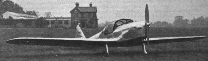
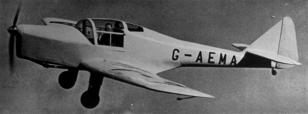
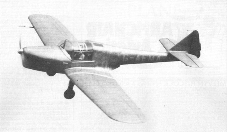
Регистрационный номер: G-AEMA [23] The general lines of the C. W. Cygnet are well shown in this Flight photograph, which also shows how the screen is arranged with quite a pronounced sweep-forward. The cleanness of the cantilever undercarriage noteworthy.
-

Flight 1937-05 / Flight
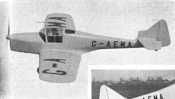
Регистрационный номер: G-AEMA [23] From a three-quarter front view the Cygnet has somewhat squat, though not unattractive lines. The prototype machine is fitted with a Cirrus Minor engine.
-

Air-Britain Archive 1980-02
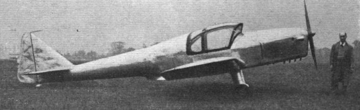
Регистрационный номер: G-AEMA [23] Application for Cygnet G-AEMA was made on 7.4.36 and it first flew at Hanworth in May 1937 with a windscreen raked forward for raindrop removal. The photo (Flight no.14718s) shows it in interim form with rounded windscreen and was probably taken at Hanworth late in 1937.
-

Flight 1938-02 / Flight
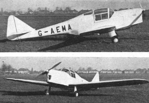
Регистрационный номер: G-AEMA [23] Two typical ground views, showing in each case the tidy cantilever undercarriage, which certainly gives an impression of ground stability
-

Flight 1938-10 / Flight
Регистрационный номер: G-AEMA [23] Recently taken over by General Aircraft, the Cygnet, which is an all-metal stressed skin medium-weight, will shortly be fitted with a tricycle undercarriage. The machine is shown here with its new twin-rudder assembly.
-

Flight 1937-09 / Flight
Регистрационный номер: G-AEMA [23] As flown in the King's Cup Race, the new C.W.A. Cygnet has the Cirrus Major 150.
-

Flight 1937-08 / Flight
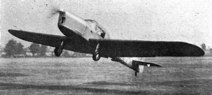
Регистрационный номер: G-AEMA [23] THE CYGNET MAJOR: The new C.W. Cygnet with a Gipsy Major engine, shown here in the act of being taken off by Mr. Wynne-Eaton at Hanworth, is one of the King's Cup entries. In the race the machine, which has been modified in certain details, will be flown by Mr. Charles Hughesdon.
-

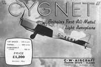
Flight 1937-11 / Flight Advertisements
Регистрационный номер: G-AEMA [23] -
Flight 1938-02 / Flight Advertisements
Регистрационный номер: G-AEMA [23] -

Flight 1938-02 / Flight
Регистрационный номер: G-AEMA [23] The flying picture gives a good idea of its smooth lines with the new cabin top and production finish.
-

Jane's All the World Aircraft 1938 / 03 - All the world's aeroplanes
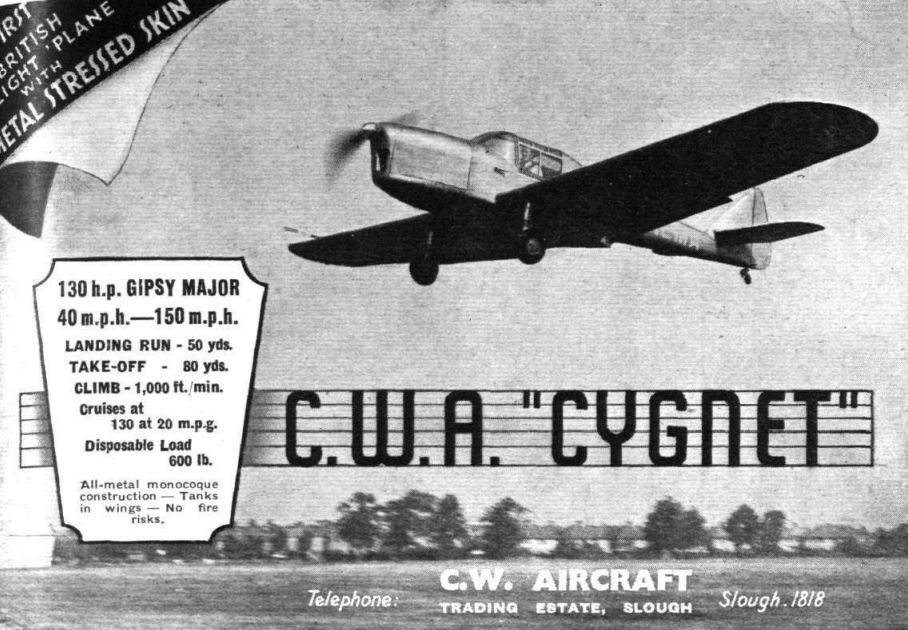
Регистрационный номер: G-AEMA [23] The G.A. "Cygnet" Two-seat Light Cabin Monoplane (130 h.p. D.H. "Gipsy-Major" engine).
-

Aeroplane Monthly 1993-05 / C.Prower - From Brisfit to Beverley (2)
Регистрационный номер: G-AEMA [23] The side-by-side two-seater CW Cygnet flying in its original form in 1937. At the time it was the smallest British all-metal stressed-skin aircraft. Priced at £895 with the 80-90 h.p. Cirrus Minor engine, it attracted little interest; the design was sold to General Aircraft, who further modified the aircraft
-
Flight 1937-06 / Flight
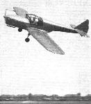
Регистрационный номер: G-AEMA [23] STRESSED SHIN IN MINIATURE. Capt. Hubert Broad flies the new C.W. Cygnet for the benefit of "Flight's" photographer. As will be seen there is a certain amount of cleaning up still to be done, but with a Cirrus Minor engine the Cygnet has a cruising speed of well over 100 m.p.h. and an 800-ft.-a-minute climb.
-

Aviation Historian 40 / R.Lezon - From West London to South America
Регистрационный номер: G-AEMA [23] The original CW Aircaft Ltd Cygnet I, G-AEMA (c/n 0001), was markedly different from the later General Aircraft Ltd production examples, the sole Cygnet I prototype having a conventional tailwheel undercarriage and single fin and rudder. It also incorporated a split trailing-edge flap running under the fuselage, as seen deployed here during landing.
-

Flight 1938-02 / Flight
Регистрационный номер: G-AEMA [23] The Cygnet’s two-piece flap gear in the “down” position
-

Air-Britain Archive 1980-02
Регистрационный номер: G-AEMA [23] The view (General Aircraft, via Aeroplane Photo Supply collection/D.M. Hannah) shows the conversion to twin fin configuration and was taken at Hanworth in November 1938. The final variation, the adoption of a tricycle undercarriage, took place early in 1939.
-

Flight 1938-02 / Flight
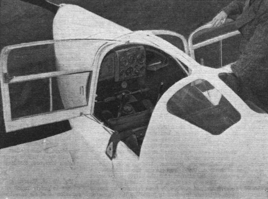
Регистрационный номер: G-AEMA [23] The wide doors of the Cygnet may be fixed in any position by means of the adjustable stops, and this photograph also shows the neat instrument panel layout, with the easily seen and reached fuel tap immediately below it. The amount of transparent area is noteworthy.
-

Flight 1938-02 / Flight
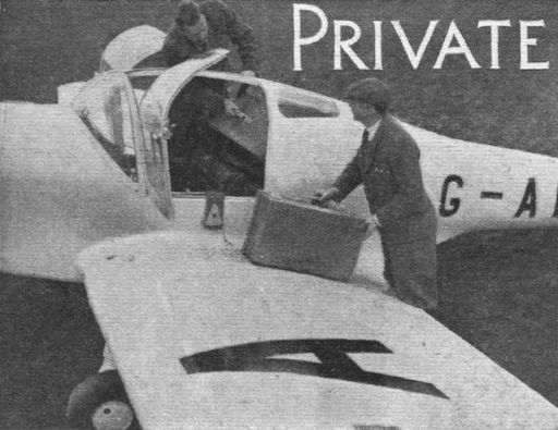
Регистрационный номер: G-AEMA [23] SPECIALISED LUGGAGE: One way of overcoming the luggage accommodation difficulty. Specially built and fitted suitcases are designed for the production model of the C.W. Cygnet
-

Flight 1937-05 / Flight
Регистрационный номер: G-AEMA [23] Side-by-side seating, with a centrally disposed control column, is a feature of the Cygnet. This Flight photograph gives an idea of the "entry area"; there is a similar door on the starboard side. In the machine are the two directors of the company, Messrs. S. I. Waddington (nearest camera) and C. R. Chronander.
-

Flight 1937-08 / Flight
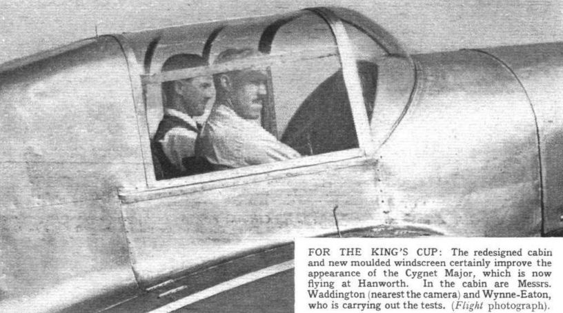
Регистрационный номер: G-AEMA [23] FOR THE KING'S CUP: The redesigned cabin and new moulded windscreen certainly improve the appearance of the Cygnet Major, which is now flying at Hanworth. In the cabin are Messrs. Waddington (nearest the camera) and Wynne-Eaton, who is carrying out the tests.
-

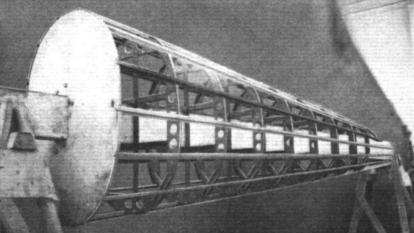
Flight 1936-12 / Flight
Регистрационный номер: G-AEMA [23] It is likely that the rear fuselage portion of the Cygnet will be simplified in production. This view shows the component for the prototype
-
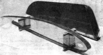
Flight 1937-10 / Flight
Регистрационный номер: G-AEMA [23] A rib and elevator in Noral, which material is being extensively employed in the production Cygnets.
-
Flight 1938-03 / Flight
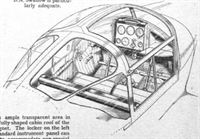
Регистрационный номер: G-AEMA [23] There is ample transparent area in the carefully shaped cabin roof of the C.W. Cygnet. The locker on the left of the standard instrument panel can be used to accommodate any special blind flying instrument panel.
-

-

Flight 1936-12 / Flight
The two main Flight sketches show the salient internal and external features and the remainder indicate structural methods.
-

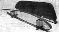
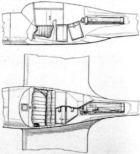
Flight 1936-12 / Flight
The basic construction of the monocoque fuselage is founded on built-up frames and "Z" section stringers..
-
Flight 1937-10 / Flight
The Cygnet accommodates pilot and passenger and has liberal stowage for luggage and sports gear. It will be seen that the seat now extends across the cabin.
-

Flight 1936-12 / Flight
C-W Cygnet Minor Cirrus Minor Engine
-

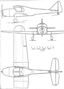
Flight 1937-03 / Flight
Stressed-skin in miniature: the CW. Cygnet Minor, which should shortly be flying.


- Фотографии