
Фотографии

-
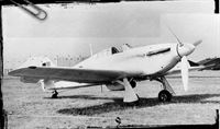
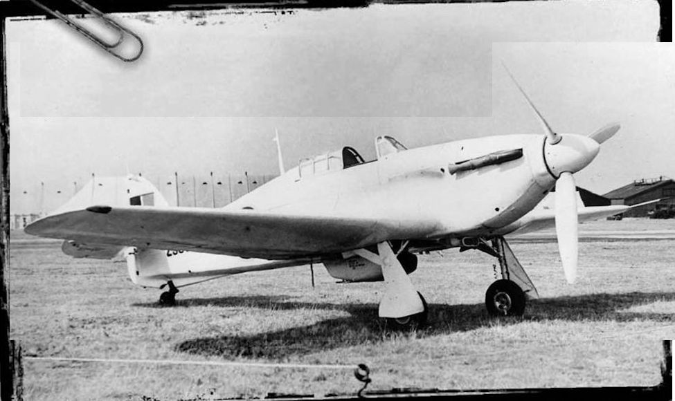
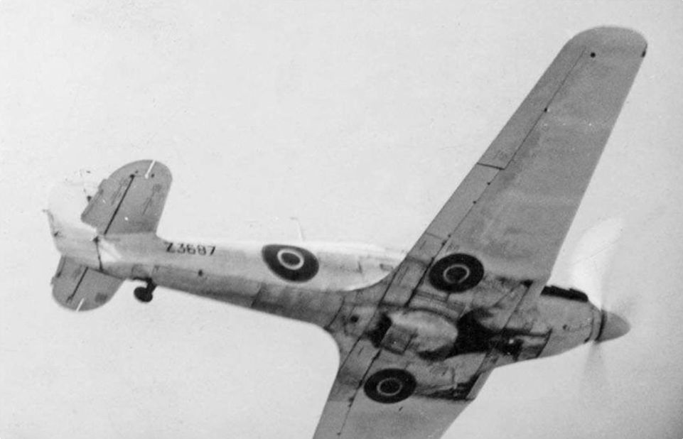
Регистрационный номер: Z3687 [2] Hawker Hurricane IIA Z3687 with Armstrong Whitworth-built laminar-flow wings, at RAE Farnborough. Note the upward-cranked leading edges of both wings just outboard of the centre section, with fairings over the transition between conventional and laminar-flow aerofoil sections. The back of the original print bears the note, "Griffiths, Boundary Layer Research Hurricane, FBoro 11/9/48”.
Самолёты на фотографии: Hawker Hurricane - Великобритания - 1935
-

Регистрационный номер: Z3687 [2] Hurricane Z3687 in its initial laminar-flow test configuration, with two Armstrong Whitworth-built wing outer sections. Later trials on a Hurricane with just the starboard wing altered by means of a sleeve have become conflated with this earlier work. Note the underwing roundels relocated to the inner sections of the hybrid wing.
Самолёты на фотографии: Hawker Hurricane - Великобритания - 1935
-

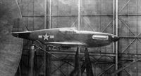
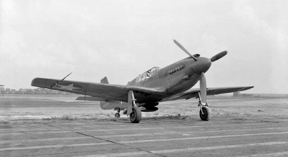
The second XP-51 prototype, 41-039, at Langley in the spring of 1943. Becoming famous as the Mustang, the type was without doubt an extraordinary achievement of both design and engineering. Innovative yet capable of being mass-produced, it was built to far more precise tolerances than were “industry standard” at the time.
Самолёты на фотографии: North American P-51 Mustang - США - 1940
-
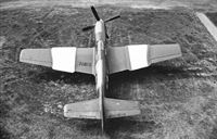
NACA aerodynamicists were eventually able to study laminar flow over the top surfaces of the Mustang’s wing by fitting “sleeves” of the same profile of the type’s standard wing, but with an ultra-smooth finish. This continued focus on attaining natural laminar flow contrasted with concurrent British work on bi-convex sections.
Самолёты на фотографии: North American P-51 Mustang - США - 1940
-
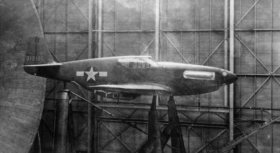
A P-51B in the full-scale NACA windtunnel at Langley in 1943. There is surprisingly little contemporary drag data available for the Mustang and almost nothing on the wing. What survives came from German and British sources and indicates that high manufacturing standards rather than laminar flow were the key to the type’s success.
Самолёты на фотографии: North American P-51 Mustang - США - 1940
-

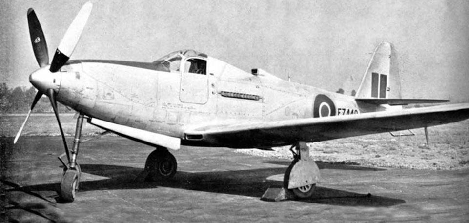
Регистрационный номер: FZ440 Bell P-63A Kingcobra FZ440, formerly serialled 42-69423 in USAAF service, was thoroughly wrung out by the RAE during 1945 in trials undertaken to explore the “real-world” behaviour of a laminar-flow wing under various conditions. The type incorporated a low-drag wing profile of NACA design; but, even with a highly polished surface, the profile drag was still deemed “much too high” by the RAE.
Самолёты на фотографии: Bell P-63 Kingcobra - США - 1942
-

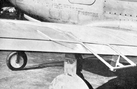
The standard method of measuring drag during the Kingcobra trials was by means of an array of pitot tubes mounted beyond the trailing edge. Comparison of recorded pressures from the array with a “free air” pitot head indicated total profile drag. Although this did not distinguish friction drag from pressure effects, it nevertheless yielded valuable aerodynamic data.
Самолёты на фотографии: Bell P-63 Kingcobra - США - 1942
-

Регистрационный номер: R4071 The first of the Miles light aircraft supplied to the RAE to be fitted with a "laminar flow" wing was M.3F Falcon Six R4071 (c/n 269). It is seen here sporting the Piercy-type aerofoil (with maximum thickness at 40 per cent chord) with which it was fitted during trials with spoilers (seen extended on the port wing) as a means of roll control.
Самолёты на фотографии: Miles Falcon M.3 / Hawcon M.6 - Великобритания - 1934
-

Регистрационный номер: K5924 Seen here before its laminar-flow modifications, Miles M.3B Falcon Six Special K5924 (c/n 252) was much used by the RAE as a wing testbed from early 1936. It was re-delivered to Farnborough circa March 1940 with a 60 per cent laminar-flow aerofoil profile (i.e. maximum thickness at 60 per cent of chord) for testing during 1940-41.
Самолёты на фотографии: Miles Falcon M.3 / Hawcon M.6 - Великобритания - 1934
-

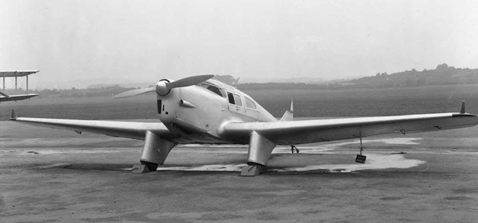
Регистрационный номер: L9705 [2] Falcon L9705 was fitted with another, far more radical, set of wings in 1944, this time intended to test prospective wing profiles for the turbojet-powered Miles M.52. These sharp, thin, bi-convex wing profiles required the undercarriage to be relocated on the “Gillette Falcon”, as it was dubbed, and were designed to combat supersonic shock, not explore laminar flow.
Самолёты на фотографии: Miles Falcon M.3 / Hawcon M.6 - Великобритания - 1934
-
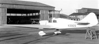
Регистрационный номер: K5925 Designed specifically as a research aircraft to investigate the effects of wing thickness on drag, the sole Miles M.6 Hawcon (c/n 187) was given the serial K5925, and arrived at the RAE in Farnborough in late November 1935. The data the tests yielded were of use to Melvill Jones for his boundary-layer lecture in New York in 1937.
Самолёты на фотографии: Miles Falcon M.3 / Hawcon M.6 - Великобритания - 1934
-

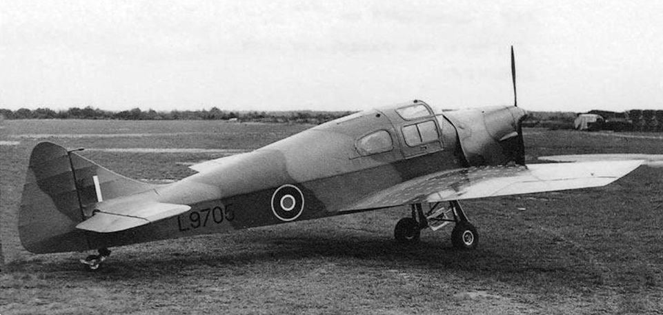
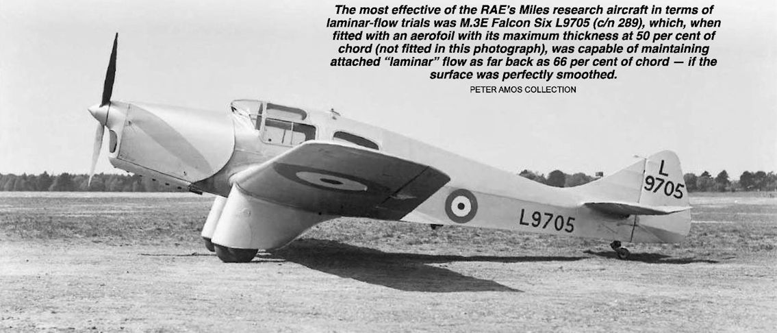
Регистрационный номер: L9705 [2] The most effective of the RAE’s Miles research aircraft in terms of laminar-flow trials was M.3E Falcon Six L9705 (c/n 289), which, when fitted with an aerofoil with its maximum thickness at 50 per cent of chord (not fitted in this photograph), was capable of maintaining attached “laminar” flow as far back as 66 per cent of chord - if the surface was perfectly smoothed.
Самолёты на фотографии: Miles Falcon M.3 / Hawcon M.6 - Великобритания - 1934
-

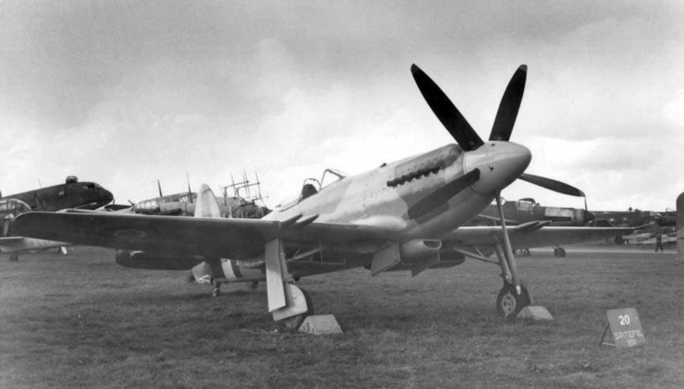
Often described as having a laminar-flow wing, the Supermarine Spiteful was in fact fitted with a hybrid aerofoil, beginning at the root as a shock-reducing shape and blending to a laminar-flow section towards the tip, away from walkways, hatches, cannon barrels and propwash, all of which would trigger significant turbulent flow.
Самолёты на фотографии: Supermarine Spiteful / Seafang - Великобритания - 1944
-

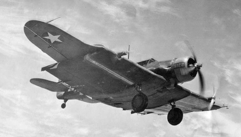
Northrop A-17 serial 35-122 was fitted with large sleeves on each wing for trials with the laminar-flow wing proposed for Douglas’s C-74 Globemaster. Each was fitted with two-bladed propellers driven by an auxiliary motor to study the effects of swirling airflow. Douglas blamed NACA for “wasting time” on laminar flow development.
Самолёты на фотографии: Northrop A-17 / 8A Nomad - США - 1934


Статьи
- -
- B.Cahill - The Mayaguez Incident
- B.Livingstone - Unbroken
- E.Wild - Say Cheese! (1)
- G.Baughen - 1939. Was the RAF ready to war?
- G.White - The world's first..?
- J.-C.Carbonel - Super-Caravelle atomique!
- J.Mesnard - Soldier of Misfortune
- J.Proctor - TWA's Skyliners
- K.Hayward - The one that got away
- M.Bearman - Going with the Flow?
- P.Davidson - Off the Beaten Track...
- P.Jarrett - Lost & Found
- R.Lezon - Southern Exposure
- S.Sumbodo - Garuda's 'Hamble Boys'