
Фотографии

-
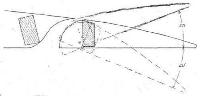
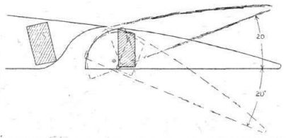
The Handley Page W 8C: Diagram of slotted and balanced aileron
Самолёты на фотографии: Handley Page H.P.18 (W.8) / H.P.30 (W.10) - Великобритания - 1919
-
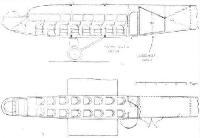
The Handley Page W 8C: Section and plan of Saloon.
Самолёты на фотографии: Handley Page H.P.18 (W.8) / H.P.30 (W.10) - Великобритания - 1919
-
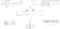
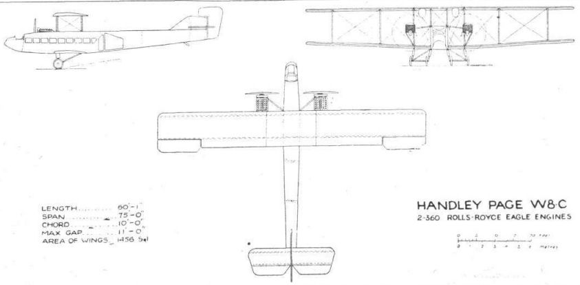
Handley-Page W8.C 2-360 Rolls-Royce Eagle Engines
Самолёты на фотографии: Handley Page H.P.18 (W.8) / H.P.30 (W.10) - Великобритания - 1919
-
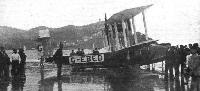
Регистрационный номер: G-EBED Vickers "Viking," Napier "Lion" engine, in Spain: Our photograph shows the machine at San Sebastian after alighting in the bay on its way to Madrid.
Самолёты на фотографии: Vickers Viking / Type 54 - Великобритания - 1919
-

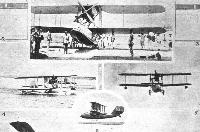
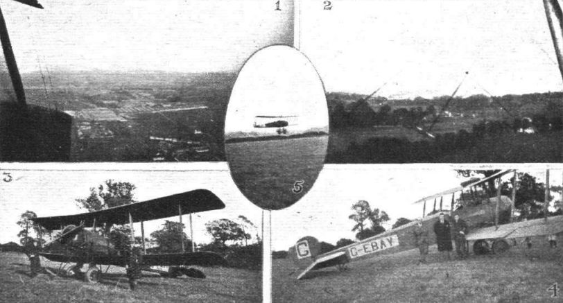
Регистрационный номер: G-EBAY WITH FRASER'S FLYING SCHOOL AT KINGSBURY: 1. View of the late Airco Works, taken from one of the school Avros. 2. Leaving the aerodrome. 3. Getting ready for a "flip" in an Avro. 4. A. Fraser J. P. C. Phillips and W. Mitchell pose for the camera beside one of the school Avros. 5, Just landing on Kingsbury Aerodrome.
Самолёты на фотографии: Avro Avro 504 - Великобритания - 1913
-

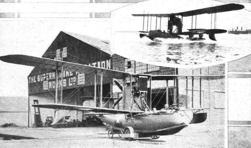
SUPERMARINES IN CHILE: A "Channel type, Mark II," with 230 h.p. Siddeley "Puma" engine. Inset, the machine taxying. Note the "cleanness" of the machine after having its front step re-designed.
Самолёты на фотографии: A.D. Flying Boat - Великобритания - 1916
-

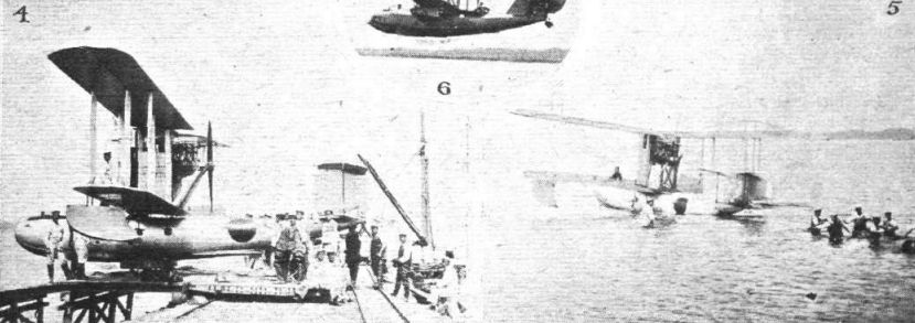
SUPERMARINES IN JAPAN: 4. A "Channel type" training machine with Siddeley "Puma" on the slipway. 5. The machine on the water.
Самолёты на фотографии: A.D. Flying Boat - Великобритания - 1916
-

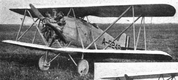
Регистрационный номер: A-6248 THE CURTISS MODEL TS BIPLANE: This machine, which was built under special contract for the U.S. Navy, can be adapted for either land or sea work, the substitution of pontoons for land gear, as seen here, being easily accomplished. Note the petrol tank formed in lower centre section.
Самолёты на фотографии: Naval Aircraft Factory TS - США - 1922
-

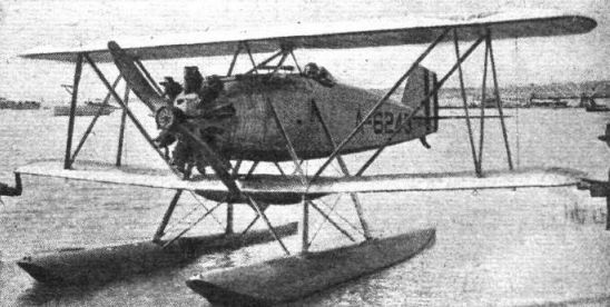
Регистрационный номер: A-6243 THE CURTISS MODEL TS BIPLANE: This machine, which was built under special contract for the U.S. Navy, can be adapted for either land or sea work, the substitution of pontoons for land gear being easily accomplished.
Самолёты на фотографии: Naval Aircraft Factory TS - США - 1922
-

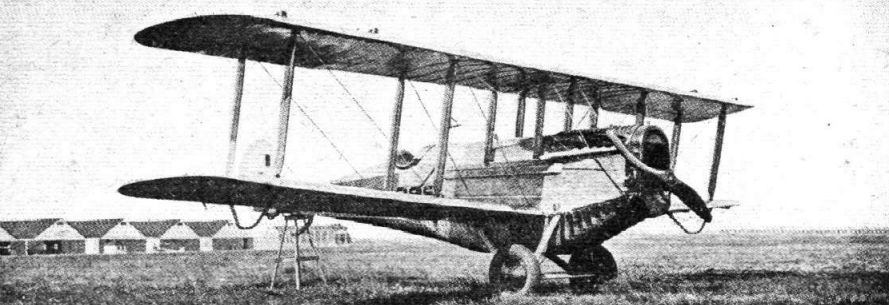
The converted D.H. Mail 'Plane of the U.S. Air Mail Service. It is fitted with A2 wings, and has 40 cu. ft. of cargo space.
Самолёты на фотографии: Boeing DH-4M / O2B / Model 16 - США - 1920
-
SUPERMARINES IN JAPAN: 1. A "Seagull" amphibian flying boat with Napier "Lion" engine. 2. The "Seagull" taxying. 3. The "Seagull" flying over land. Note the lowered undercarriage. 6. The "Seagull" in flight. Note the gunner's cockpit aft of the planes.
Самолёты на фотографии: Supermarine Seal / Seagull - Великобритания - 1921
-

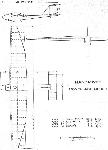
THE KLEMPERER "DUCK": Plan view of the machine, with main dimensions, etc., shown.
Самолёты на фотографии: FVA (Flugwissenschaftliche Vereinigung Aachen) FVA-1 Schwatze Duvel/FVA-2 Blaue Maus/FVA-3 Ente - Германия - 1920
-
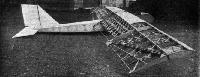
The Handasyde Glider: View of the machine in skeleton, taken during construction at Addlestone.
Самолёты на фотографии: Handasyde glider - Великобритания - 1922
-

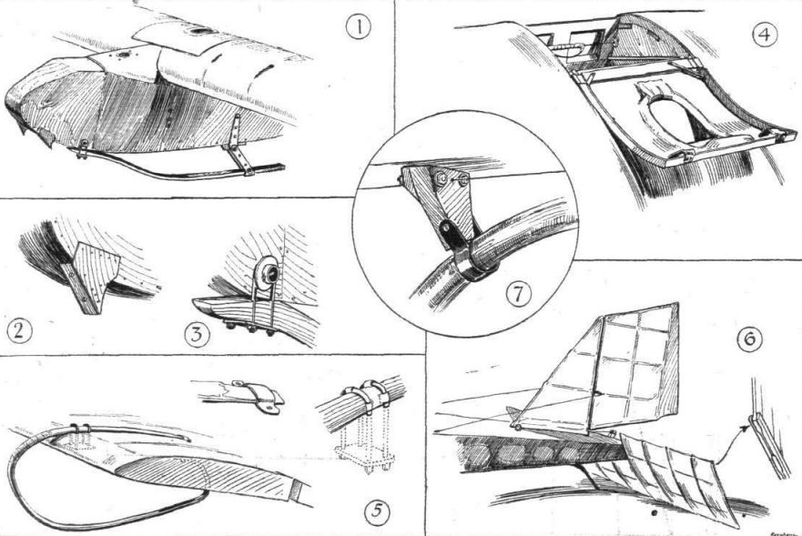
THE HANDASYDE MONOPLANE GLIDER: Some constructional details. 1. The nose of the machine, showing landing skids. 2. One of the cleats which support the launching rope during the start. 3. Front attachment of landing skid. 4. Cover over cockpit thrown back. When the cover is pulled down the pilot's head projects through the small opening. Note the hand guard on the aileron cable. 5. Details of a wing tip skid. 6. The tail. 7. Detail of tail skid attachment.
Самолёты на фотографии: Handasyde glider - Великобритания - 1922
-
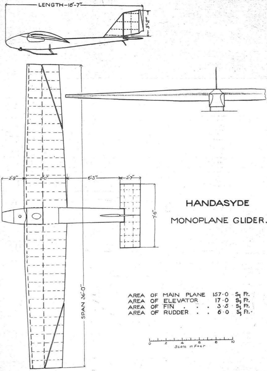
Handasyde Monoplane Glider
Самолёты на фотографии: Handasyde glider - Великобритания - 1922
-
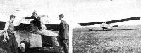
THE WHITELEY BANK SCHOOL OF GLIDING: On the left Mr. Merriam is seen getting out of his machine after a trial flight. Mr. Newman, who had a large share in building the machine, is standing by the nose. On the right, the Merriam-Newman glider is seen just before touching after a flight.
Самолёты на фотографии: Merriam glider - Великобритания - 1922
-

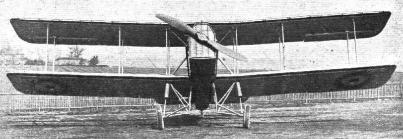
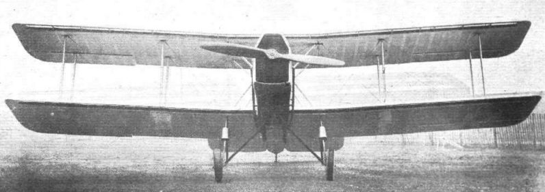
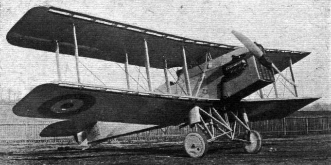
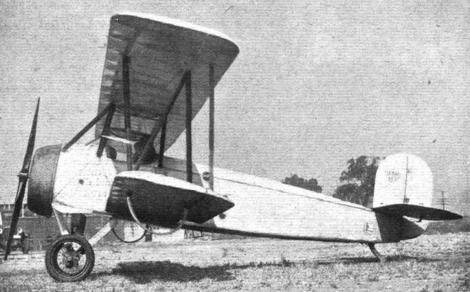
THE HANDLEY PAGE "HANLEY" TORPEDO 'PLANE: The front view gives a very good idea of the divided undercarriage which gives accommodation for the torpedo. The machine is fitted with slotted planes, and has slotted ailerons, which are found to be effective right up to the stalling angle.
Самолёты на фотографии: Handley Page Hanley/H.P.19 / Hendon/H.P.25 - Великобритания - 1922
-

THE HANDLEY PAGE "HANLEY" TORPEDO 'PLANE: Front view.
Самолёты на фотографии: Handley Page Hanley/H.P.19 / Hendon/H.P.25 - Великобритания - 1922
-

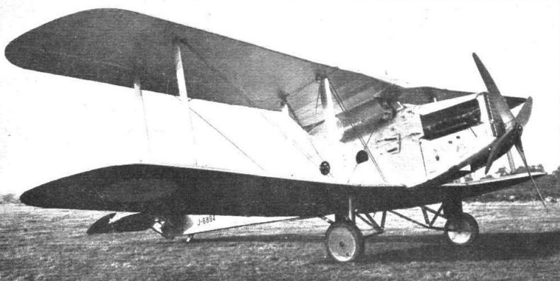
Another view of the Handley Page "Hanley'' torpedo 'plane, 450 h.p. Napier "Lion" engine: Three-quarter front view. The slots can be clearly seen in the picture. Although this machine is officially known as the "Hanley," it is affectionately called the "Heintz," owing to the number of levers which the pilot has to operate.
Самолёты на фотографии: Handley Page Hanley/H.P.19 / Hendon/H.P.25 - Великобритания - 1922
-

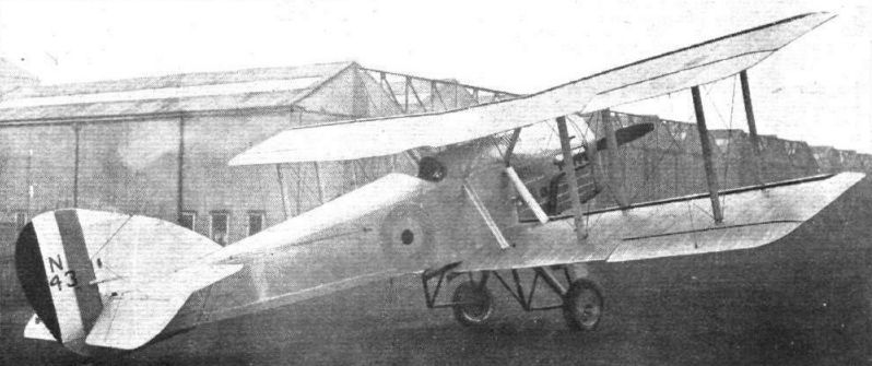
Регистрационный номер: N143 [2] THE HANDLEY PAGE "HANLEY": Side view.
Самолёты на фотографии: Handley Page Hanley/H.P.19 / Hendon/H.P.25 - Великобритания - 1922
-

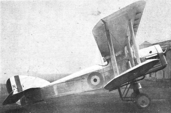
Регистрационный номер: N143 [2] THE HANDLEY PAGE "HANLEY": Three-quarter rear view.
Самолёты на фотографии: Handley Page Hanley/H.P.19 / Hendon/H.P.25 - Великобритания - 1922
-

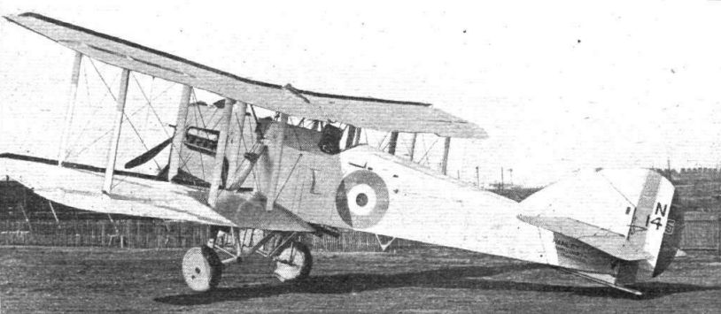
Регистрационный номер: N145 THE HANDLEY PAGE "HANLEY": Three-quarter rear view.
Самолёты на фотографии: Handley Page Hanley/H.P.19 / Hendon/H.P.25 - Великобритания - 1922
-

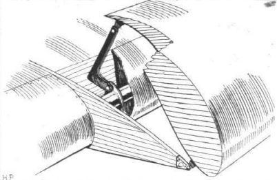
Slot-operating mechanism of the Handley Page "Hanley."
Самолёты на фотографии: Handley Page Hanley/H.P.19 / Hendon/H.P.25 - Великобритания - 1922
-

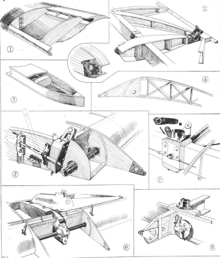
THE HANDLEY PAGE "HANLEY": Some constructional details of the wings. 1, partly-sectioned view of a portion of the auxiliary aerofoil. In shape this resembles the famous Joukowsky wing section. 2, shows the construction of an aileron. Note the triangulated construction. The shackle near the trailing edge receives the wire to the top aileron, while the fitting on the nose fo the rib shown in more detail in the inset sketch, is for the return cable. 3, section of the end portion of a built-up box spar. Note the triangular section corner strip, which provides large glued area. In 4 is shown one of the double lattice ribs which carry the brackets on which the auxiliary aerofoil is mounted. The nose of the main aerofoil is formed by thin three-ply, bent over the small curved strip screwed to the bracket. 5, details of the locking pin and spar fitting on the lower plane at the point where the wing is joined for folding. A lever is used for pulling back the locking bolt when the vertical slide at the back has been raised. 6, details of the slot operating mechanism. The tube from the pilot's controls carries on its front end a worm, which engages with a worm wheel on the transverse tube in the leading edge. Rotation of this tube raises or lowers the auxiliary aerofoil through levers hinged to lugs on the tube, thus opening or closing the slot. 7, inter-plane strut socket on the lower plane rear spar. 8, lower spar, with bracket for aileron hinge.
Самолёты на фотографии: Handley Page Hanley/H.P.19 / Hendon/H.P.25 - Великобритания - 1922
-

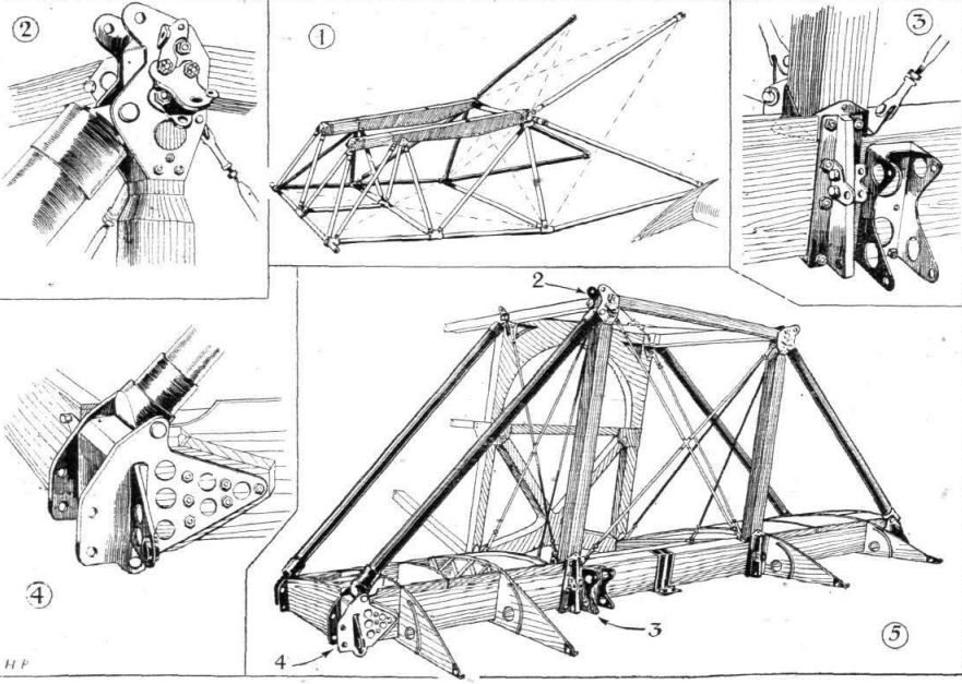
THE HANDLEY PAGE "HANLEY": Some constructional details. 1, View of the engine mounting. 2, Attachment of sloping strut to vertical strut and longeron. 3, Brackets for attachment of engine tubes and slot control gear. 4, Lower attachment of sloping strut to wing root spar. The lug projecting forward carries the slot control tube. 5, General view of front portion of fuselage with lower wing spar roots, sloping tubes, etc.
Самолёты на фотографии: Handley Page Hanley/H.P.19 / Hendon/H.P.25 - Великобритания - 1922
-

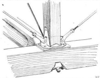
Standard fuselage fitting of the Handley Page "Hanley."
Самолёты на фотографии: Handley Page Hanley/H.P.19 / Hendon/H.P.25 - Великобритания - 1922
-

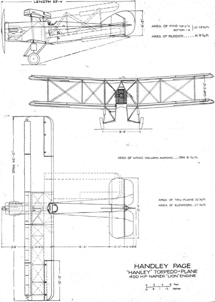
Handley Page "Hanley" Torpedo-Plane 450 hp Napier "Lion" Engine
Самолёты на фотографии: Handley Page Hanley/H.P.19 / Hendon/H.P.25 - Великобритания - 1922
-

The Dayton-Wright "Chummy" Training Biplane: A two-seater side-by-side machine, fitted with a Le Rhone 80 h.p. engine. In September last a student of the Dayton-Wright Co., K. M. Lane, who had never previously touched the controls of a 'plane, started to take instruction on one of these machines early in the morning, and that evening made his first solo flight. His total instruction time was 4 hrs. 26 mins. His instructor was W. E. Lees.
Самолёты на фотографии: Dayton-Wright Chummy - США - 1922
-

Регистрационный номер: J6894 [2] THE NEW DE HAVILLAND BOMBER, TYPE D.H.27, "DERBY," fitted with Rolls-Royce Condor engine: Three-quarter front view.
Самолёты на фотографии: De Havilland Derby / DH.27 - Великобритания - 1922
-

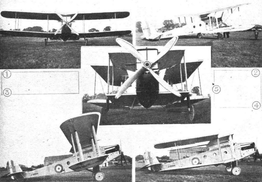
Регистрационный номер: J6894 [2] THE NEW DE HAVILLAND BOMBER: Known as the D.H.27 "Derby," this Machine is fitted with a Rolls-Royce "Condor" engine. The Air Ministry has sanctioned publication of these photographs, but no details may be given. 1. Front view. 2. Three-quarter rear view. 3. Side view with wings extended. 4. Side view with wings folded. 5. Close-up view of machine with wings folded.
Самолёты на фотографии: De Havilland Derby / DH.27 - Великобритания - 1922


Статьи
- Flight