
Фотографии

-
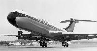
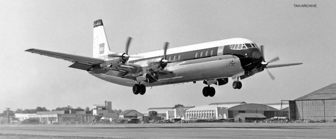
Регистрационный номер: G-ASGA The silver lining? The VC7 had been conceived from the outset as a fast, economical airliner for BOAC’s vital North Atlantic routes, a type finally delivered with the advent of the Super VC10 - the prototype of which, G-ASGA, made its maiden flight in May 1964, and which is seen here at Farnborough in September the same year.
Самолёты на фотографии: Vickers VC-10 - Великобритания - 1962
-
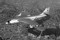
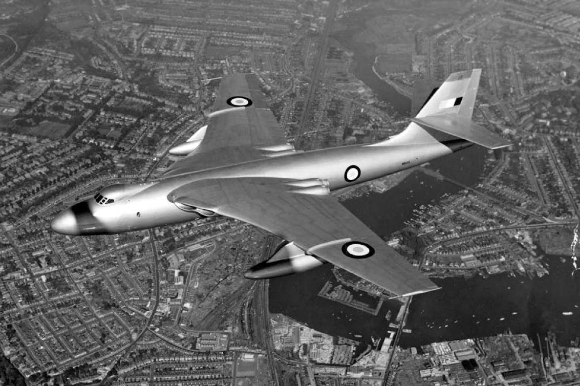
Регистрационный номер: WB215 The second prototype Vickers Valiant, WB215, photographed by Charles E. Brown soon after its first flight in April 1952. Vickers’ Type 716 proposal for a jet-powered replacement for the Handley Page Hastings was to use the wings, tail unit and undercarriage of the Valiant, fitted to a new fuselage capable of carrying at least 90 troops.
Самолёты на фотографии: Vickers Valiant - Великобритания - 1951
-

In 1953 the Vickers design team began exploring a larger, improved Viscount, to become the Vanguard, which was developed entirely as a private venture. The type’s extensive development became another burden on the already hard-pressed Vickers production team.
Самолёты на фотографии: Vickers Vanguard - Великобритания - 1959
-
Регистрационный номер: XD662 [8] The sole V.1000 under construction at Wisley.
Самолёты на фотографии: Vickers VC-7/V.1000 - Великобритания - 1957
-
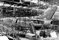
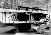
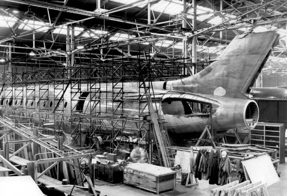
Регистрационный номер: XD662 [8] The sole V.1000 prototype, allocated RAF serial XD662, being built at the Vickers factory at Wisley. Most of the components were fabricated at the company’s experimental site at Foxwarren, between Weybridge and Wisley, then transported to Wisley for final assembly. The fin was built as an integral part of the fuselage rear section.
Самолёты на фотографии: Vickers VC-7/V.1000 - Великобритания - 1957
-
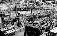
Регистрационный номер: XD662 [8] Engineers work on the Vickers V.1000 during its assembly at Wisley in the mid-1950s,
Самолёты на фотографии: Vickers VC-7/V.1000 - Великобритания - 1957
-
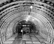
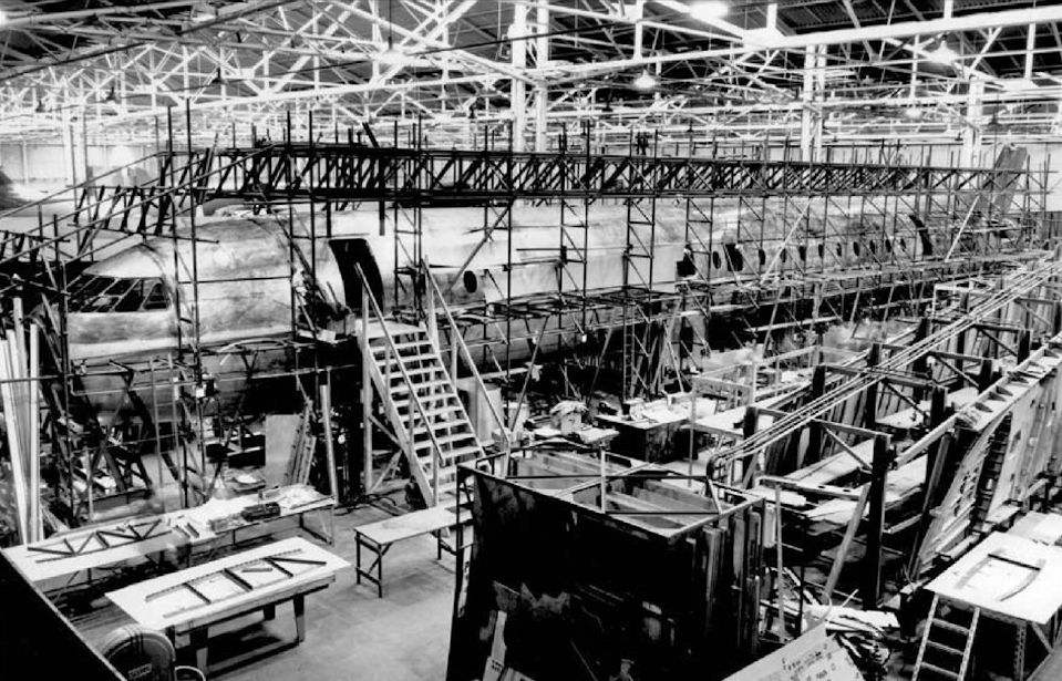
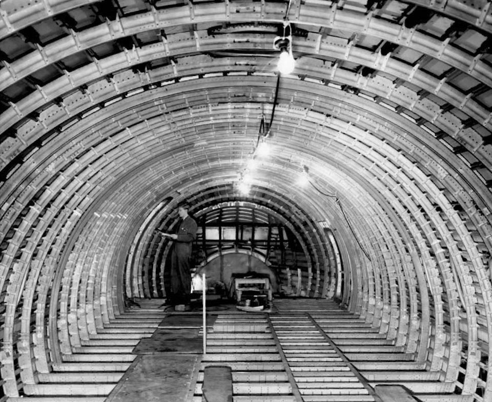
Регистрационный номер: XD662 [8] Inside the V.1000 fuselage looking forward. The fuselage was 137ft 11 in (42m) long with a diameter of 12ft 6in (3-8m), with a stringer-skin structure supported by light channel-section frames; Z-section stringers were fixed to the skin with countersunk rivets. The frames were attached to the stringers and not directly to the skin.
Самолёты на фотографии: Vickers VC-7/V.1000 - Великобритания - 1957
-
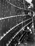
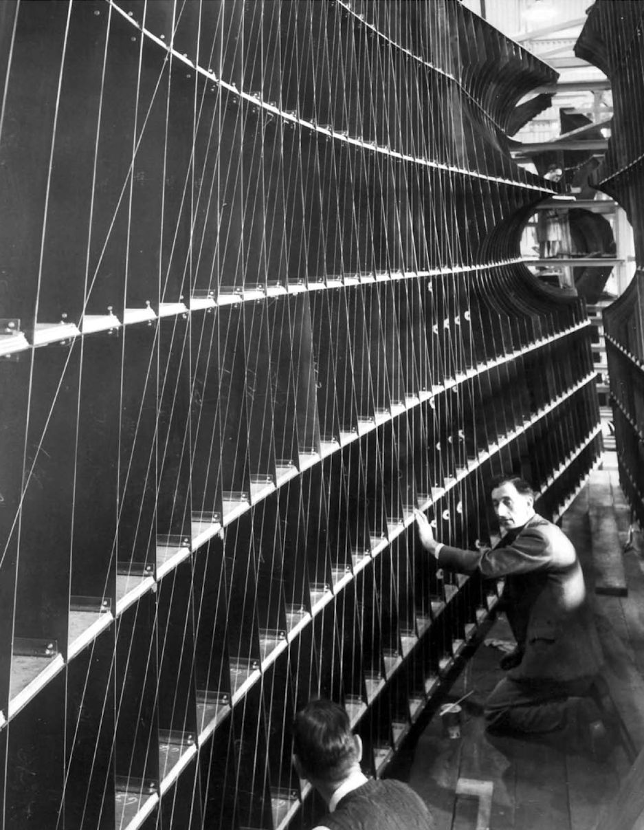
Регистрационный номер: XD662 [8] The air intake apertures on the V.1000’s port wing. The engines were to be buried in the wing roots but placed well out from the fuselage to reduce noise levels in the cabin and avoid jet-efflux effects on the rear fuselage. The inner wing sections were given a sweep of 38° 24', with the outer sections having a sweep of 26° 23'.
Самолёты на фотографии: Vickers VC-7/V.1000 - Великобритания - 1957
-
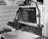
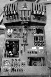
Регистрационный номер: XD662 [8] The mock-up of the navigator’s station, with instrumentation illustrations for positional purposes, in the V.1000 prototype at Wisley
Самолёты на фотографии: Vickers VC-7/V.1000 - Великобритания - 1957
-
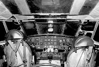
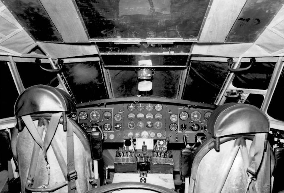
Регистрационный номер: XD662 [8] The flightdeck of the prototype at Wisley during construction. Crew accommodation for the military V.1000 included positions for five crew, comprising two pilots, a flight engineer, a navigator and a signaller. The 140ft (42-67m) span of the V.1000 was considerably greater than the 114ft 4in (34-83m) span of its original forerunner, the Valiant.
Самолёты на фотографии: Vickers VC-7/V.1000 - Великобритания - 1957
-
Регистрационный номер: XD662 [8] The throttle quadrant and central control pedestal, incorporating the braking parachute-release switch (between throttles at top) and trim controls (beneath parachute switch).
Самолёты на фотографии: Vickers VC-7/V.1000 - Великобритания - 1957
-
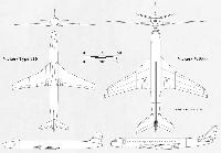
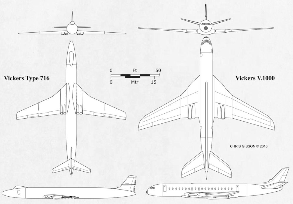
LEFT A provisional drawing by CHRIS GIBSON of an initial Valiant-based low-wing study for Vickers’ Type 716, based on documents in The National Archives. By the end of 1952 the firm had dispensed with the Valiant elements and was working on the V.1000, the military version of which, with dorsal spine, is seen RIGHT.
Самолёты на фотографии: Vickers VC-7/V.1000 - Великобритания - 1957


Статьи
- -
- A.Metzmacher - Local Hero
- D.Powers - Bunny Power!
- J.Franzi - A Proper Firebomber /An eye for detail/
- J.Knightly - The Last Seagull
- J.Pote - New Year on Skyline Ridge
- J.Stroud - Beirut: Lebanon's Propliner Paradise /The John Stroud Archive/
- K.Hayward - The Blame Game
- M.O'Leary - Magical Mystery Tourer
- N.Braas - Machtrainer
- N.Stroud - The Hot Seat
- P.Davidson - Off the Beaten Track...
- P.Jarrett - Lost & Found
- P.Jarrett - Mr. Cody & Mr. Roe (1)
- P.Thompson - Young Japan
- R.Flude - The Molotov Express