Hampden / H.P.52
Средний бомбардировщик, двухмоторный цельнометаллический моноплан с двухкилевым оперением, убирающимся шасси с хвостовым колесом. Экипаж 4 - 5 человек. Спроектирован в КБ фирмы "Хэндли-Пейдж" под руководством Г.Лачманна. Первый полет совершил 21 июня 1936 г. ДальшеMore>>>
Серийное производство начато в июне 1938 г. Выпускался заводами "Хэндли-Пейдж" (Криклвуд), "Шорт энд Гарланд" (Белфаст), "Инглиш электрик" (Сэмлсбюри), "Кэнедиэн асошиэйтед эйркрафт" (Мэлтон, Сент-Губерт). Всего построено 1580 экз.
Вооружение первых серий 4x7,69, последующих - 6x7,69; многие самолеты доработаны в частях в вариант 8x7,69. Бомбы до 1250 кг.
Самолет состоял на вооружении в Великобритании с августа 1938 г., в СССР - с октября 1942 г., в Канаде - с начала 1941 г.
Выпускался в двух основных вариантах:
- "Хэмпден" I с моторами "Пегасус" XVIII;
- "Хирфорд" I с моторами "Дэггер" VII.
С сентября 1939 г. "хэмпдены" применялись британскими ВВС для дневных и ночных операций над морем, включая постановку мин у побережья Германии. С декабря 1939 г. действовали только ночью, участвуя в налетах на цели в Германии, в т.ч. в августе 1940 г. в первом английском налете на Берлин. В конце 1940 г. вынужденно применялись как ночные истребители. Как бомбардировщики использовались до сентября 1942 г., затем были переделаны в торпедоносцы "Хэмпден" TBI (эксплуатировались до середины 1943 г.)
Самолеты "Хирфорд" в боевых условиях почти не применялись и служили в основном как учебные. В СССР самолеты модификации TBI имелись в ВВС Северного флота, где действовали как ночные бомбардировщики и торпедоносцы. В Канаде эти машины использовались только для учебных целей.
Производство прекращено в Англии в марте 1940 г. "Хэмпдены" сняли с вооружения в Великобритании в конце 1943 г., в Канаде - в конце 1944 г. Все советские "хэмпдены" были потеряны в боях к июню 1943 г.
"Хэмпден" I||
Размах:||21,01 м
Длина:||16,28 м
Моторы, количество х мощность:||2x10¹⁵ л.с.
Взлетная масса, максимальная:||8525 кг
Максимальная скорость:||406 км/ч
Практический потолок:||6920 м
Дальность:||1920 км
Hampden ТВ.I
Торпедоносец на базе среднего бомбардировщика, двухмоторный цельнометаллический моноплан с двухкилевым оперением и убирающимся шасси. Спроектирован в КБ фирмы "Хэндли-Пэйдж" под руководством Г. Лачманна. Опытный образец "Хэмпдена" совершил первый полет 21 июня 1936 г. Серийное производство начато в июне 1938 г. Выпускался заводами "Хэндли-Пэйдж" (Криклвуд), "Инглиш электрик" (Сэмлсбюри), "Кэнэдиан ассошиэйтед эйркрафт" (Мэлтон, Сент-Губерт). Всего построено 1580 экз. Производство прекращено в марте 1940 г.
Экипаж - 4-5 чел. Моторы "Пегасус" XVIII. Вооружение 6x7,69, в СССР переделывалось под стандарт 1x12,7+ 4x7,69.
Опытный образец торпедной подвески был испытан на "Хэмпдене" в марте 1942 г. Самолет мог нести бомбы до 1250 кг или одну торпеду (907 кг) в бомбоотсеке. Сразу же начата переделка бомбардировщиков в торпедоносцы на заводе "Инглиш электрик" в Сэмлсбюри. Всего переделано до октября 1942 г. 144 экз.
Самолет состоял на вооружении Берегового командования ВВС Великобритании с апреля 1942 г., в СССР -с ноября 1942 г. Британские торпедоносцы использовались в боевых операциях в Северном море с мая 1942 г. В сентябре того же года базировались под Мурманском в составе сил прикрытия конвоя PQ-18.
Обратно они не вернулись - их передали авиации советского Северного флота. Машины дорабатывались местными авиамастерскими под новое вооружение, монтировалась система нейтрального газа. Бомбоотсек удлиняли под торпеды советского образца. "Хэмпдены" применялись одним из полков ВВС Северного флота с ноября 1942 г. как разведчики, торпедоносцы и ночные бомбардировщики.
В Великобритании "хэмпдены" сняли с вооружения в декабре 1943 г. В Советском Союзе все имевшиеся машины были потеряны в боях к июлю 1943 г.
"Хэмпден" TB.I||
Размах:||21,01 м
Длина:||16,28 м
Моторы, количество х мощность:||2x10¹⁵ л.с.
Взлетная масса, максимальная:||10660 кг
Максимальная скорость (с торпедой): 406 км/ч||
Практический потолок (с бомбами): 6920 м||
Дальность (с бомбами):||1920 км
Handley Page H.P.52 Hampden
В сентябре 1932 года Министерство авиации Великобритании подготовило техническое задание B.9/32 на двухмоторный бомбардировщик, в рамках которого свои предложения представили компании "Handley Page" и "Vickers", с каждой из которых был заключен контракт. Появившиеся в результате этого прототипы H.P.52 и Vickers Type 271 совершили свои первые полеты с недельным интервалом: H.P.52 - 21 июня 1936 года (с двумя двигателями Bristol Pegasus PE.5-SM (Pegasus XVIII)), а модель Vickers Type 271, ставшая позже Wellington, - 15 июня. Учитывая, что эти самолеты были разработаны по одному техническому заданию, они вряд ли могли сильно отличаться. Однако компания "Handley Page" использовала очень тонкий фюзеляж с тремя пулеметами с ручным управлением, а компания "Vickers" выбрала фюзеляж большего размера, оборудованный автоматическими турелями и установленными в самой широкой части фюзеляжа пулеметами с ручным управлением.
Самолет Hampden, как впоследствии был назван бомбардировщик H.P.52, имел несколько особенностей: использование предкрылков типа Хендли Пейдж по передней кромке крыла снизило посадочную скорость до 117 км/ч, хотя его максимальная скорость 409 км/ч была большей, чем у самолетов Wellington и Armstrong Whitworth Whitley, и самолет мог брать 1814 кг бомбовой нагрузки.
15 августа 1936 года компания получила заказ на 180 самолетов Hampden Mk I по новому техническому заданию B.30/36, а в 1937 году свой первый полет совершил опытный серийный самолет. Одновременно с первым контрактом был подписан другой - на 100 самолетов H.P.53 Hereford с двигателями Napier Dagger VIII.
В мае 1938 года первый серийный самолет Hampden Mk I совершил свой первый полет на аэродроме компании в Радлетте. Расширение боевого состава британских ВВС стало причиной того, что 6 августа 1938 года поступили другие заказы: от компании "English Electric" на 75 самолетов, а в Канаде шли переговоры с консорциумом "Canadian Associated Aircraft Ltd" на производство 80 самолетов. Эти построенные по субподряду Hampden начали сходить с конвейера в 1940 году.
После испытаний в сентябре 1938 года машины стали поступать в британские ВВС - в Исследовательский центр самолетов и вооружения в Мартлешем-Хит и Центральную летную школу в Упавоне. Первая партия бомбардировщиков поступила в 49-ю эскадрилью в Скемптоне, графство Линкольншир. Эскадрилья была частью 5-й группы, которая почти полностью была вооружена бомбардировщиками Handley Page Hampden.
С началом Второй мировой войны самолетами этого типа были оснащены 10 эскадрилий: 7-я и 76-я в Финнингли, 44-я и 50-я в Уоддингтоне, 49-я и 83-я в Скемптоне, 61-я и 144-я в Хемсвелле и 106-я и 185-я эскадрильи резерва. 29 сентября в одном из вылетов 5 из 11 самолетов были уничтожены вражескими истребителями - отчетливо выявились недостатки самолетов в оборонительном вооружении. Вскоре было принято решение об использовании этих самолетов ночью, они также участвовали в психологических операциях - разбрасывали листовки. К зиме 1939-1940 годов самолеты Hampden эффективно применялись в качестве минных заградителей - бомбардировщики пяти эскадрилий в ночь с 13 на 14 апреля 1940 года, сразу после немецкого вторжения в Норвегию, успешно минировали немецкие воды, а к концу года самолеты 5-й группы поставили 1209 мин.
Однако норвежская кампания еще раз подтвердила недостатки самолетов Hampden: из-за слабого оборонительного вооружения они не могли противостоять немецким истребителям, особенно когда использовались в качестве дневных бомбардировщиков.
В ночь с 25 на 26 августа 1940 года бомбардировщики Hampden и Whitley приняли участие в первом воздушном налете британских ВВС на Берлин. Самолеты Hampden продолжали вести наступательные ночные бомбардировки вплоть до конца 1942 года. В ночь с 15 на 16 сентября самолеты канадских ВВС из состава 408-й эскадрильи нанесли удар по Вильгельмсхафену - это были последние вылеты самолетов Hampden в составе Бомбардировочного командования. С апреля 1942 года самолеты начали переводиться в Береговое командование для выполнения торпедно-бомбовых ударов - 157 машин, переоборудованных под эту задачу, получили обозначение Hampden TB.Mk I. Первыми такие машины получили 144-я и 455-я эскадрильи, причем группы из состава обеих эскадрилий были отправлены в СССР для проведения операций по сопровождению конвоев. 4 сентября 1942 года 32 самолета из двух эскадрилий покинули базу на Шетландских островах. Девять из них были потеряны во время перелета, еще два разбились в Норвегии и один - во время посадки в СССР. Перед тем, как покинуть СССР 23 октября, летчики передали свои самолеты советским пилотам.
455-я эскадрилья, базировавшаяся в Сумбурге, была последней, эксплуатировавшей данные машины. Самолеты привлекались к операциям против немецких подлодок. 4 апреля 1943 года была потоплена одна подводная лодка, а в конце 1943 года самолеты Hampden закончили свою службу, им на смену в Береговом командовании пришли Bristol Beaufighter. Несмотря на многие недостатки, самолет имел и ряд преимуществ: хорошая управляемость и хороший обзор для пилота. Но условия, в которых находились экипажи, были весьма некомфортны. Всего были построены 1432 машины: 502 из них произвела компания "Handley Page", 770 самолетов - "English Electric" и 160 самолетов были построены в Канаде.
Варианты
Hampden Mk II: обозначение двух самолетов с экспериментальной силовой установкой в составе двух звездообразных ПД Wright R-1820 Cyclone мощностью по 1100 л.с. (фирменное обозначение самолета H.P.62)
ТАКТИКО-ТЕХНИЧЕСКИЕ ХАРАКТЕРИСТИКИ
Handley Page Hampden Mk I
Тип: средний бомбардировщик с экипажем из четырех человек
Силовая установка: два звездообразных ПД Bristol Pegasus XVIII мощностью по 1000 л. с. (746 кВт)
Летные характеристики: максимальная скорость на высоте 4205 м - 409 км/ч; крейсерская скорость на оптимальной высоте 269 км/ч; начальная скороподъемность 299 м/мин; набор высоты 4570 м -18 мин 54 с; практический потолок 5790 м; дальность полета 3034 км - с бомбовой нагрузкой 907 кг
Масса: пустого 5343 кг; максимальная взлетная 8508 кг
Размеры: размах крыла 21,08 м; длина 16,33 м; высота 4,55 м; площадь крыла 62,06 м2
Вооружение: один 7,7-м пулемет Vickers или Browning впереди слева в верхней части фюзеляжа, один 7,7-мм наводимый пулемет Vickers "K" в носовой части, один или два 7,7-мм наводимых пулемета Vickers "K" в надфюзеляжной установке для обороны задней полусферы и один или два таких же пулемета в подфюзеляжной установке - также для обороны задней полусферы, плюс до 1814 кг бомб в бомбоотсеке в нижнем крыле и на двух подкрыльевых узлах подвески - обычно нагрузка включала две 907-кг бомбы, либо четыре или шесть 227-кг бомб, либо мины, либо одну 457-мм торпеду Mk XII
Flight, May 1939
A VERY REMARKABLE AEROPLANE
Details of the Handley Page Hampden Disclosed : Unusual Production Methods Based on “Split” Construction
(Illustrated with “Flight“ Photographs and Drawings)
THE specialised experience of the Handley Page Company in the construction of multi-engined bombing aircraft is brilliantly reflected in the design of the Hampden monoplane, which for some months has been in quantity production for R.A.F. bomber squadrons. Not only is the Hampden an outstandingly efficient weapon, capable of high speeds, of long range and of carrying a heavy military load, but, thanks to its unorthodox design, would be well able to defend itself if intercepted by enemy fighters.
Ease of production and maintenance has not been sacrificed to military effectiveness. On the contrary, the Hampden is probably the easiest machine of its type in the world to build owing to features which will be described here. Only by seeing the Hampdens in production at the Cricklewood works can one thoroughly appreciate the ingenuity of its design.
The Hampden is a three/four-seater mid-wing cantilever monoplane of all-metal construction. As at present in production it is powered with two Bristol Pegasus XVIII nine-cylinder radial engines fitted with two speed superchargers.
When a crew of four is carried it consists of: (a) a pilot, who also operates the fixed gun ; (b) navigator/bomber, who has charge of the front lower gun; (c) wireless operator, who is also the top rear gunner; and (d) a lower rear gunner.
The Hampden is unique among our multi-engined bombers in that it has no power-driven turrets, three of its four machine-guns being fired from a manually operated mounting, while the fourth is fixed.
The pilot’s fixed gun is so arranged as to fire through a port in the nose just aft of the transparent section. Below this is a floor mounting for a machine gun which can be completely detached from its mounting and stowed in the fuselage. The top fuselage gun, which is set rather forward of the trailing edge of the wing, would be used mainly to fire aft between the twin rudders. The gunner who operates this weapon is shielded by a spring-loaded transparent dome. Located at the bottom rear corner of the fuselage ”box,” the lower rear gun has a particularly wide field of fire in a rearward and downward direction. The gunner is entirely within the fuselage, and the gun is easy to train without mechanical assistance.
A heavy load of bombs is carried in a bay in the bottom of the fuselage; additional bombs, carried in the “overload” condition, may be slung outboard of the engine nacelles under the wings. The bomb aimer (who is also the navigator) is situated in the extreme nose of the fuselage from which an exceptionally wide and clear view is obtainable. An optically flat circular Triplex panel is built into the nose section to facilitate bomb aiming.
The Service load includes wireless, which is installed in the rear part of the top rear gunner’s station, and can be operated from the same seat; an automatic pilot; and an automatic camera, which is fitted immediately below the wireless set. Each member of the crew is provided with an exit to enable him to use his parachute.
The machine is fitted with the latest type of blind-flying and fog-landing equipment.
As at present in production, the Hampden is fitted with two Bristol Pegasus XVIII engines. The Pegasus XVIII is rated at 815 h.p. at 4,750ft., using medium supercharge, and 750 h.p. at 14,750ft. using lull supercharge. The take-off output is 965 h.p., and the maximum power for all-out level flight (five minutes) is 1,000 h.p. at 3,000ft., or 885 h.p. at 15,500ft. Alternative engines of the Pegasus series (e.g., Pegasus XXV or XXVI) could equally well be installed. In any case, the engines would be fitted with the standard Bristol long-chord cowling embodying a leading-edge exhaust collector with single outlet and adjustable cooling gills on the trailing edge.
The Hampden could, alternatively, be equipped with in line engines of liquid- or air-cooled type, notably the Rolls Royce Merlin X (1,030 h.p. max. at 16.250ft. with two-speed supercharger in high gear) or the Napier Dagger VIII (1,000 h.p. max. at 8,750ft.). With the latter engines the machine is, in fact, built under the name Hereford by Short and Harland, of Belfast.
With Pegasus XVIII engines the Hampden is normally fitted with three bladed De Havilland constant-speed airscrews.
If one were looking for proof of the contention that, provided the size of the initial order is sufficiently large, the rate of production can be greatly speeded-up by careful study of production problems during the design stage, such proof is furnished by the Hampden. The following notes, and a considerable proportion of the illustrations, are therefore devoted to the production aspect.
Assembly has always been the bottle-neck of production, whether it be the assembly of the innumerable "bits and pieces" of which a modern aircraft structure is composed, or whether it be the installation of the almost incredible range of equipment and "services" necessary for the proper functioning of a military aeroplane. That this must necessarily be so is obvious when one stops to consider that the manufacture of small parts and components can be speeded-up to any desired extent by multiplying the number of machines and operators: but when the various "bits and pieces" meet on the aircraft only a limited number of men can get to work on assembling them without getting in one another’s way. So with the installation of equipment. Once the shell of a fuselage, for example, is completed, the number of men who can be accommodated inside for the purpose of mounting and connecting-up the instruments, armament, hydraulic and electric services, and so forth, in short, attend to "the plumbing," is obviously limited.
“Split” Construction
Realising this, the Handley Page Company decided, when the Hampden was being planned, to attack the problem in a different and more logical way. The aerodynamic design, as one may term it, once decided upon, the drawing office and the works got together, and, after a good many discussions, one may suppose, evolved the scheme on which the Hampden was ultimately produced. For its working this scheme is so completely dependent upon the closest co-operation between structural design and production that in the follow ing notes the two must be dealt with concurrently.
The foundation of the scheme was actually laid in connection with the previous Handley Page bomber type, the Harrow. When the initial order for Harrows was received it was, however, not of a size to justify very extensive jigging and tooling. Consequently, the scheme could not be carried to its logical conclusion, and a sort of halfway measure had to be adopted.
In the Hampden, however, the initial order was sufficiently large to justify much greater expenditure on jigs and tools, and consequently the principle could be carried almost to its logical conclusion. Not quite, because even the Hampden order was not sufficiently large to extend the desirable production methods down to the last small detail. However, the fundamental principle is there and can be applied to any type, so long as the size of order makes it financially possible.
Briefly explained, it may be stated that the "theme" of the Hampden production is to adopt a "split" form of construction. This can best be illustrated by taking the fuselage as an example. Instead oi building this in one piece, or in two at the most, the fuselage of the Hampden is divided first into three main parts, the front portion, the centre portion and the tail portion. The last two ol these are again divided into two halves, with a vertical "split" down
the centre.
Three advantages result from this scheme. Actual assembly of the structure is facilitated, because by splitting the fuselage into two halves, a port side and a starboard side, riveting becomes an easy operation, as there are no inaccessible corners where holding up is difficult. A second advantage is that when equipment is being installed and electrical or hydraulic leads have to be run along, the men can stand up to the work in convenient positions, and there is never at any time any need for crawling about on hands and knees or lying down in order to get at some out-of-the-way piece of equipment or inaccessible pipe union. The third advantage is that complete interchangeability is ensured.
A somewhat similar scheme is followed tn the construction of the wings. This consists of three main units: the centre section, the port outer wing and the starboard outer wing; but each of these is again sub-divided into smaller units, so that during assembly almost any desired number of men can be put to work by duplicating the number of units. Before the smaller units are assembled into larger units, some of the equipment and installation which goes in the wing is secured in place, so that when, finally, the larger wing units go together it is only a question of connecting up such leads, wires or controls as pass from one unit to the other.
In discussing the Handley Page Hampden type of construction, we have frequently met with the objection that, although the "split" type of construction may be very fine from a production point of view, it must of necessity entail extra structure weight. An examination of the Handley Page Hampden construction does not show any signs of such added weight, and actual figures disclose the interesting fact that the structural weight of the machine - that is to say, the airframe without engines - is only 32 per cent, of the normal gross weight. This figure actually includes a certain amount of structure which carries fixed equipment but which is not actually a part of the aircraft structure There are probably few comparable machines which show such a good figure of airframe weight.
In its general structural design the Handley Page Hampden is of the usual stressed-skin type. That is to say, the external sheet metal covering carries part of the stresses and is reinforced by local stringers, frames, etc Considerable use is made throughout the structure of extruded sections. In fact, these are used wherever the gauge makes an extrusion economical. In the lighter gauges this would not be so, and there bent-up sheet metal strip is used instead of extrusions. Apart from their good mechanical properties, the use of extruded sections has the advantage that a good deal of work in the aircraft factory is saved. The drawback is, of course, the very obvious one that the aircraft constructor is entirely dependent on the manufacturer of extruded sections for his supplies. If there is any delay in delivery, the production in the aircraft manufacturer's shop is inevitably held up.
In these notes we do not propose to devote much space to the actual forming and manufacture of the small components. The usual processes are employed for pressing and drawing sections, and the Handley Page works do not differ materially from others in this respect. Where they are unique is in the system of assembly, and it is to this aspect that we propose to devote most of the space available.
The Fuselage
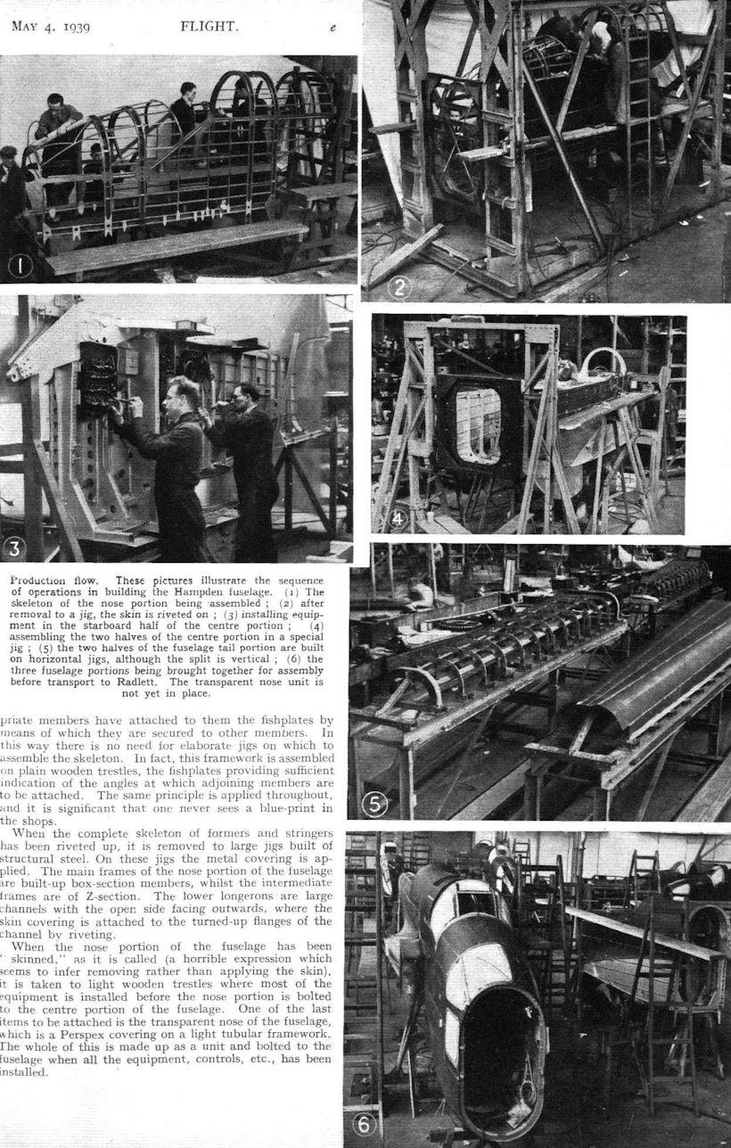
As already mentioned, the fuselage of the Hampden is made in three main units, of which the central and rear portions are again divided into two halves, port and starboard. The nose portion is not so divided, because during its assembly it is open at both ends and partly at the bottom, so that the men can get at the inside quite comfortably, and there was no real necessity to split it into two halves. The hoops, formers and stringers which compose its skeleton framework are manufactured in the shop, and the appropriate members have attached to them the fishplates by means of which they are secured to other members. In this way there is no need for elaborate jigs on which to assemble the skeleton. In fact, this framework is assembled on plain wooden trestles, the fishplates providing sufficient indication of the angles at which adjoining members are to be attached. The same principle is applied throughout, and it is significant that one never sees a blue-print in the shops.
When the complete skeleton of formers and stringers has been riveted up, it is removed to large jigs built of structural steel. On these jigs the metal covering is applied. The main frames of the nose portion of the fuselage are built-up box-section members, whilst the intermediate frames are of Z-section. The lower longerons are large channels with the open side facing outwards, where the skin covering is attached to the turned-up flanges of the channel by riveting.
When the nose portion of the fuselage has been "skinned," as it is called (a horrible expression which seems to infer removing rather than applying the skin), it is taken to light wooden trestles where most of the equipment is installed before the nose portion is bolted to the centre portion of the fuselage. One of the last items to be attached is the transparent nose of the fuselage, which is a Perspex covering on a light tubular framework. The whole of this is made up as a unit and bolted to the fuselage when all the equipment, controls, etc., has been installed.
The middle portion ol the fuselage is, as already mentioned, built in two halves, a port and a starboard. In the front part of this fuselage section the longerons are channel sections with a flat covering strip on the inside In the rear part, however, the longerons are plain open channels, with the open side facing downwards. The main frames are of built-up box-section of light gauge, while the intermediate frames are of Z-section. The wing fairings of the centre-section are built integral with the centre portion of the fuselage. The skeleton of each half is assembled on trestles horizontally, and the riveting is done on very simple wooden jigs. When removed from the jigs these frameworks are, of course, very flexible, but when they are in place on the metal jigs in which the skin covering is applied they are held rigid and prevented from distorting. These large jigs each hold two fuselage halves, one port and one starboard.
Installing equipment
Probably due largely to the fact that the wing root fairings are built integral with the fuselage halves, these are fairly stiff when they leave the jigs in which the "skinning" is done. Consequently, they deform but little when being removed from the main jig to be transferred to the light wooden jigs on which they rest while such items as wiring, piping and equipment are being installed.
It is here that, in following the process through at the Cricklewood works, one first begins to appreciate the cleverness of the type of production adopted for the Hampden. While a very few jigs serve for keeping pace with the skinning operation, many more may be needed for the installation of equipment. These simple wooden jigs, actually little more than slightly elaborated trestles, can readily be duplicated at very low cost, so that the installation of equipment can never form the "bottleneck" which it is likely to form with more orthodox methods of production.
Naturally, not all of the equipment can be installed while the central fuselage portion is in two halves. A certain amount, and such items as floors, etc., must necessarily be carried on transverse structure members. However, the percentage of equipment which has to wait until the two fuselage halves are joined together is relatively small.
Fairly elaborate jigs built ot structure steel are used tor assembling the port and starboard portions of the fuselage. But only a small number of them is required, as the operation of joining the two halves together is not a lengthy one. In these jigs the cross-members are put in, and the butt joints of frames and formers are secured by fishplates. The top of the fuselage is still open, and is covered, also in this jig, by a "lid" formed by the cambered top decking. In these jigs also the bomb "bay" is built on to the bottom of the fuselage, and the hinged doors attached, as well as the necessary wiring for the bomb-operating gear.
The Tail-carrying Boom
Elsewhere in the works the two halves of the fuselage rear portion have been manufactured. This portion of the fuselage is a very simple tapering tube with flat sides and rounded corners. It is “split” vertically like the middle portion of the fuselage, and has formers of simple Z-section and rather elaborate stringers, which can, perhaps, be described as being built up of two "Fig. 2" sections, of which the curl of one goes over the outside of the curl of the other (see sketch) The stringers, bv the way, are joggled into the frames in order to provide smooth lines for the application of the skin.
The port and starboard halves of the tail portion of rhe fuselage have their frameworks assembled and skins attached on horizontal jigs. They are then transferred to an assembly jig, in which they are rigidly held by their ends while the joint between the two halves is being made. For the frames this joint takes the form of fishplates, but for the skin a somewhat unusual system has been adopted. The “plank” nearest the joint is left slightly wide, and an L-section strip is riveted on the outside. The free edge of the skin plank is then turned up to lie along the vertical limb of the L-section. When the two halves are brought together in the jig, a strip of bisection is placed over the free edges and the whole riveted together. The process is extremely simple from the manufacturing point of view, and the only projections are the two U-section strips which run fore and aft and so probably add nothing appreciable to the air drag.
On their way down the shop the different fuselage portions gradually assume a more and more finished form until they finally meet at the far end, where the nose, middle and tail portions are brought together and joined. The joint between tail and middle portions is particularly simple. This is due to the fact that it occurs so far aft that there is no equipment to interfere, and a very straightforward joint can be made. The front end of the fuselage tail portion and the rear end of the middle portion have end frames of extruded L-section. One limb of each L is riveted to the fuselage skin. The other lies flat against the corresponding limb of the frame of the other fuselage portion, and the two limbs are secured by numerous bolts.
The joint between middle and nose portions is of a totally different kind. Owing to the fact that much equipment, and certain highly stressed structure members, are involved at this point, it has been necessary to design a form of "four point mounting" with very substantial bolts and lugs for carrying the concentrated stresses at these points. On the other hand, the task of connecting and disconnecting the front or nose portion from the middle portion of the fuselage is greatly facilitated.
So carefully has been the jigging of the fuselage portions on their various stages that when the three main parts meet at the end of the shop, no jig is necessary for their assembly. The middle portion has inserted in the place where ultimately the wing centre-section will go a dummy undercarriage on which the fuselage is transported to Radlett. This dummy undercarriage forms the support while the fuselage is finally assembled and the few remaining items of equipment installed. When the last cover strip of the joints in the skin has been put in place, the fuselage, now complete, is wheeled into the dope shop.
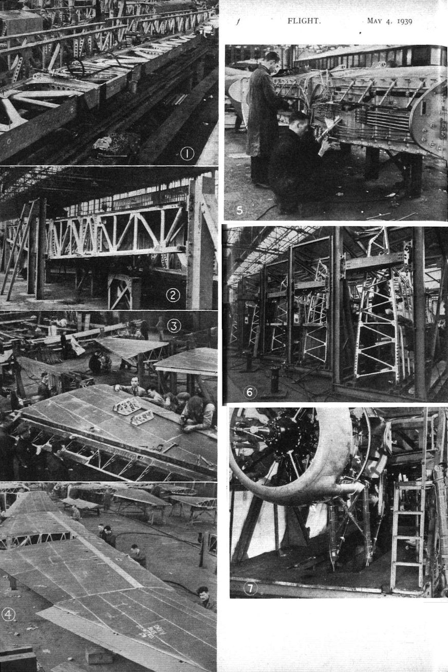
In the construction of the Hampden wing the key member is the large single main spar. This takes all the bending loads, while sheer and torsion bracing is provided by the spar box and the stressed-skin covering. The main spar has flanges ot built-up construction, consisting of two extruded T-sections placed side by side, a plain, heavy-gauge strip on top of the two Ts, and a thin sheetmetal covering strip which forms part of and serves as attachment for the rest of the sheet covering.
Generally the vertical and diagonal braces between spar flanges are duralumin tubes, but in places where concentrated stresses are found, or where certain components or equipment have to be attached to the wing structure, the braces are of built-up box-section. These sections are of very simple construction, consisting of two channels opposite one another, with the free edges turned outwards, and two flat strips on the other two sides. By this arrangement the lines of rivets are very accessible.
The spar “box” comprises a solid front wall or false spar, the rib channels and tubular braces. The box is, for ease of manufacture, built on to the centre-section main spar in five units. The trailing portion of the wing is of similar construction, but of lighter gauge material in view of the lower stresses in it. Instead of a false spar of ordinary type, this portion of the wing terminates in a curved strip to form the fixed portion of the slot between flap and wing. The extreme leading edge is a trough of U-section, attached to the lower edge of the false front spar by “piano” hinges. It is built in short units. Not only does this form of construction facilitate access to the leads, engine controls, etc., carried on the front wall of the spar box, but in case of damage to a leading edge the chances are that only a short unit will need replacement.
Outer wing portions are of generally similar construction to the centre-section, with the exception that the main spar has a solid web, and flanges of extruded L-section. On their leading edges they carry the automatic slots, and on the trailing edges the Frise ailerons. Each outer wing portion is attached to the centre-section by four bolts; two large ones on the ends of top and bottom flanges of the main spar, one near the upper edge of the front spar wall, and one a short distance ahead of the junction of flaps and ailerons to the trailing edge. The two latter are quite light fittings, and almost the entire load is taken by the two very large bolted joints on the main spar flanges.
In order to “close” the spar box and to give access for inspection of the internal structure during the subsequent life of the machine, the under-surface of the wing has two straight (non-tapering) panels, about 8in. wide, running the entire span. These panels are located adjacent to the lower spar flange, and piano hinges are provided along one edge of each. Finally, the three main wing portions pass to the main assembly jig, in which they are bolted together and the interchangeability assured.
The production “flow” system may be described as a lateral inflow of small pieces from the different shops into two parallel longitudinal lines, one the fuselage components and the other the wing components. Owing to the “split” type of production one does not see anywhere in the works the familiar rows of finished or nearly finished fuselages and wings. When the three fuselage portions meet the centre-section at the far end of the shop, they are bolted together temporarily for transport by road to the works at Radlett aerodrome. There the fuselage is removed from the road chassis and finally assembled on the wing, resting on the proper undercarriage, which has been attached in the meantime.
At the Cricklewood works elaborate jigs are used for the assembly of the engine mountings. Each jig carries two mountings, back to back, and all the engine equipment which goes in the mounting unit is installed there. The undercarriages are also assembled on these jigs, pits in the concrete floor of the shop permitting of the undercarriage being fully extended for test.
One feature of the Handley Page works system which deserves mention is that nowhere does one see a blueprint. Presumably they were used when production first started, but by now the men have become so accustomed to the work that they do not need drawings to guide them. This obviously saves a good deal of time.
The type of production adopted at Cricklewood could equally well be introduced elsewhere. For example, there does not appear to be any reason why, if Hampdens are wanted in larger quantities than the parent firm can produce, the great shipbuilding concerns should not undertake the work. Handley Page, Ltd., have had to train a large percentage of their workers, and the shipbuilding firms could do the same. Already something of the sort is taking place in that the English Electric Company, Ltd., by arrangement with Handley Page, Ltd., and the Air Ministry, is building the Hampden at Preston. In Canada the machine is to be built by the Canadian Central Aircraft Corporation.
Flight, November 1939
Britain's Military Aircraft
A Survey of Our Service Machines
HANDLEY PAGE
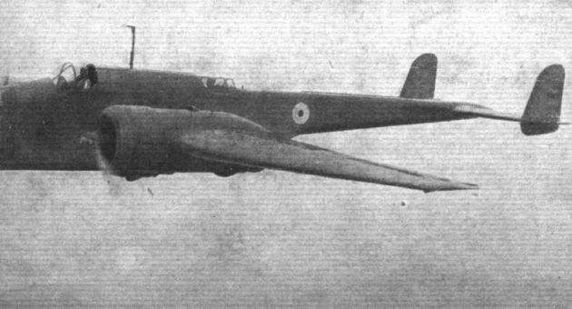
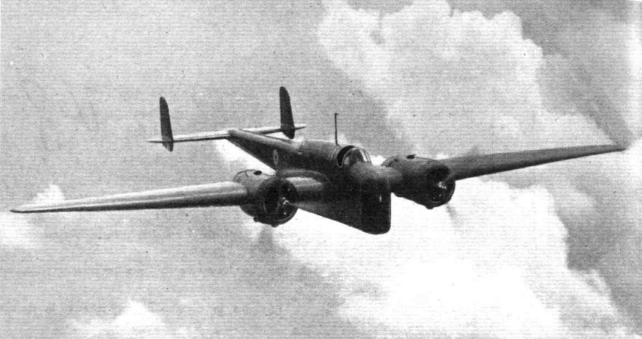
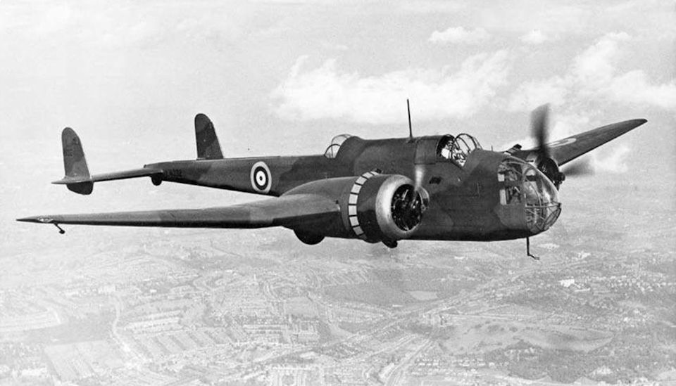
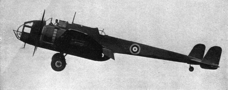
BOMBING aircraft have always been the Handley Page forte. Latest of the line to go into service with the R.A.F. is the Hampden, a twin-engined, mid-wing monoplane of unorthodox appearance. The wings are sharply tapered, and the fuselage, though of clean design, is unusual in that the rear part becomes abruptly small, lessening the wetted area, and permitting a good field of fire for the rear guns.
The fine performance of the Hampden is due in a large measure to the fitting of Handley Page automatic slots and hydraulically operated split flaps. The machine is of all-metal construction with flush riveted, stressed-skin covering. Of cantilever type, the tail has twin fins and rudders.
The engines are two Bristol Pegasus XVIIIs fitted with two-speed superchargers and driving three-bladed De Havilland constant-speed variable-pitch airscrews.
Bombs are stowed in the centre section, and there are four machine guns. One of these is fixed in the nose and is fired by the pilot; a second fires downward from the nose; the third is operated from on top of the fuselage roughly in line with the trailing edge of the wing; and the fourth is mounted to fire rearward and downward from the lower end of the box-like forward section of the fuselage.
The crew consists of a pilot, navigator-bomber, wireless operator-gunner, and lower rear gunner.
Dimensions are: Span, 69ft. 4in.; length, 53ft. 4in.; wing area, 668 sq. ft.; weight, empty, 11,780 lb.; gross weight (normal), 18,756 lb.; top speed, 265 m.p.h. at 15,500ft.; cruising speed (normal r.p.m.), 217 m.p.h.; economical cruising speed, 167 m.p.h.; service ceiling, 22,700ft.; maximum range at economical speed with 2,587 lb. load, 1,790 miles.
Handley Page. Ltd.. Cricklewood. London, N.W.2.
Prototype
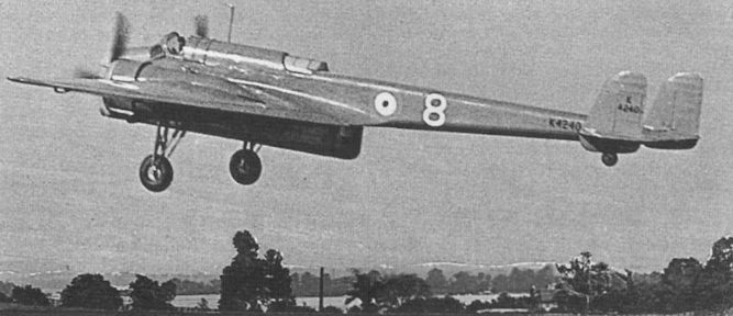
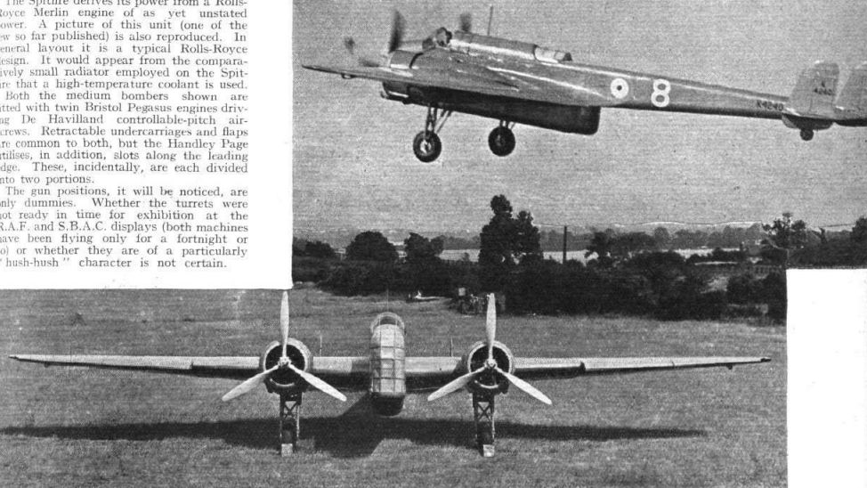
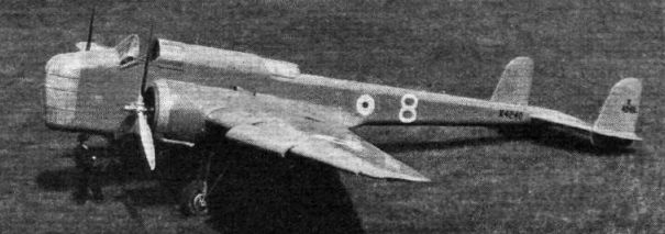
HIGH LIFT: HIGH SPEED. The new Handley-Page medium bomber with two Pegasus engines, controllable-pitch airscrews, slots and flaps, and retractable undercarriage. It is painted a sombre mud colour, which may signify a revision of official colour schemes.
The H.P.52 prototype, with modified Heyford ventral turret, takes off from Radlett in July 1936.
The same aircraft in its RAF Display configuration, with the nose glazing sheeted over with aluminium to hide its interior from public gaze.
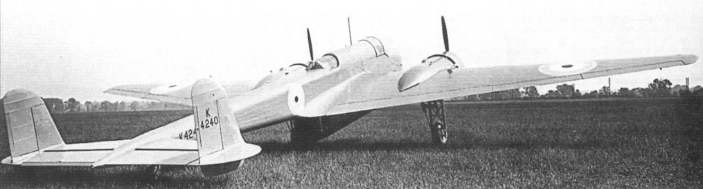
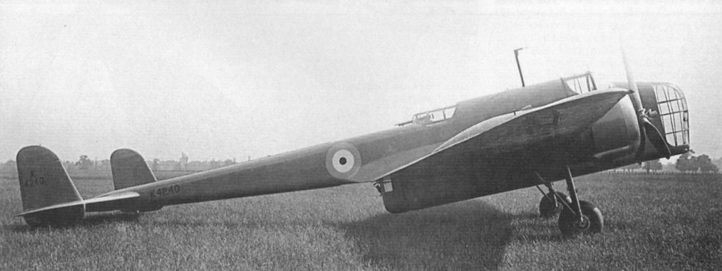
Handley Page medium bomber (two views).
Прототип H.P.52 (K4240) был полностью окрашен глянцевой краской серо-зеленого цвета. Впервые самолет публично продемонстрировали в июле 1936 года на авиашоу британских ВВС в Хендоне.
K4240 photographed in the late summer of 1936; it was painted glossy grey-green all over. In the H.P.52 or Hampden slots and flaps have taken the place of the early plan form, and the power has gone up to about 1,500 h.p.
The Handley Page Hampden (two Pegasus) will very soon be in service in considerable numbers. The nose of the production type will be more rounded than in the photograph.
The striking lines of the H.P.52 medium bomber are well brought out here.
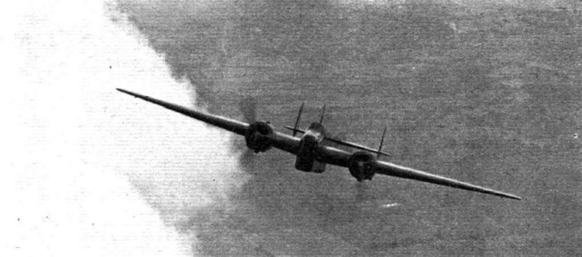
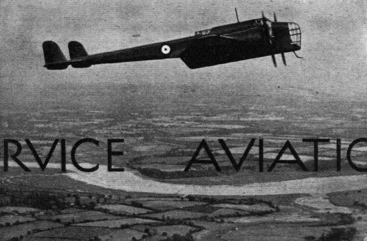
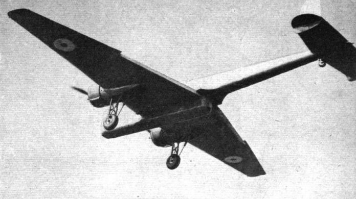
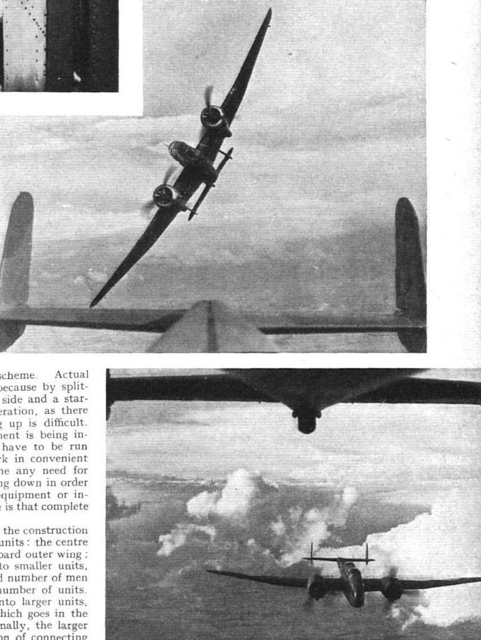
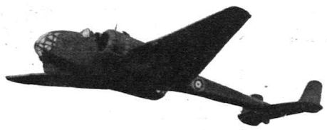
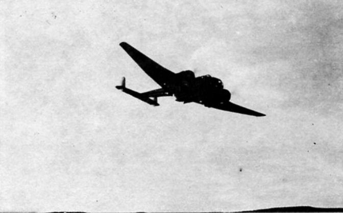
INTERCEPTOR FASHION: The climb of the new Handley Page medium bomber, in this striking picture, suggests the fighter of not so very many years ago.
VISIBLE PITCH: Careful study of this Flight photograph of a Handley Page Hampden will reveal spirals of vapour trailing from the airscrew tips. The photograph is untouched.
The Flight photograph referred to in the Editorial footnote to "Commonwealth’s" letter. The vortices visible at the airscrew tips have been very slightly touched-up for reproduction purposes, but they are just as clearly visible in the untouched original, and the picture is in no way "faked."
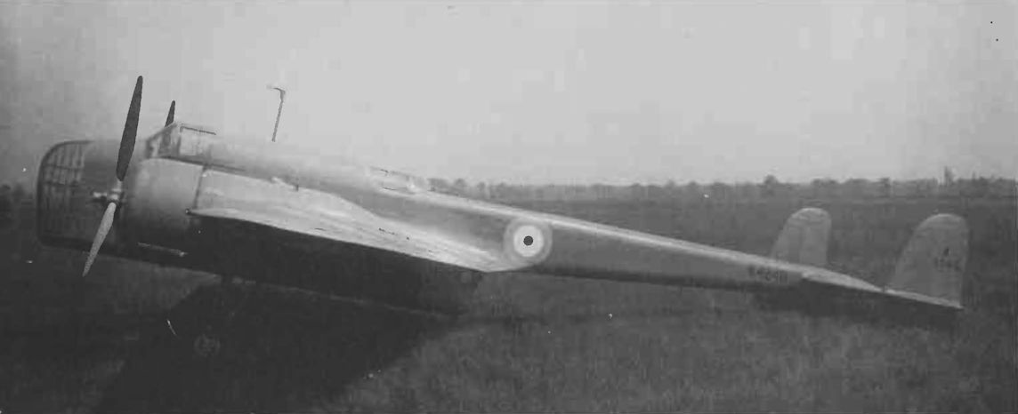
SLIM AND DARK: Off the ground, and with wheels retracted, the new Handley Page medium bomber (two Pegasus engines and C.P. airscrews) has a sinister beauty of line. For this photograph - the first taken with wheels up - the machine was "posed" by Capt J. B. L. H. Cordes, the makers' chief test pilot.
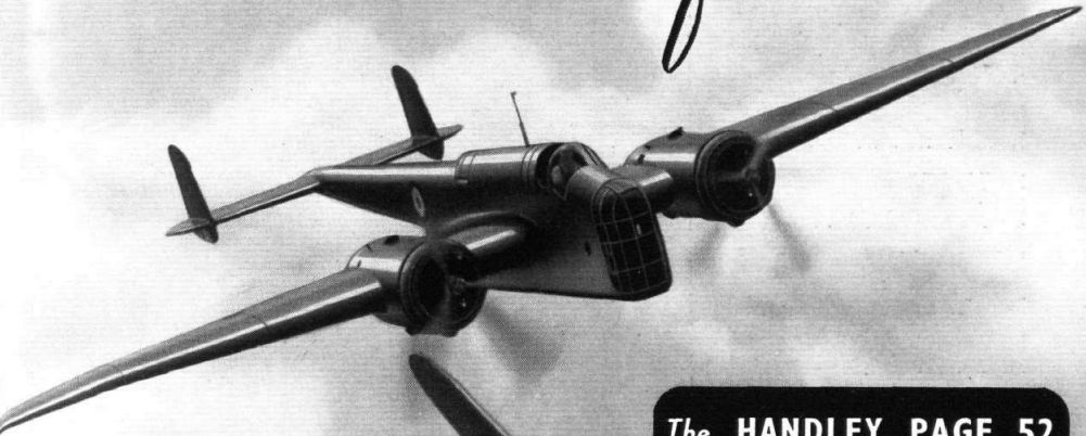
The HANDLEY PAGE 52 HEAVY BOMBER
The prototype Handley Page Hampden medium bomber.
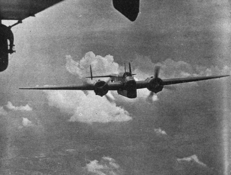
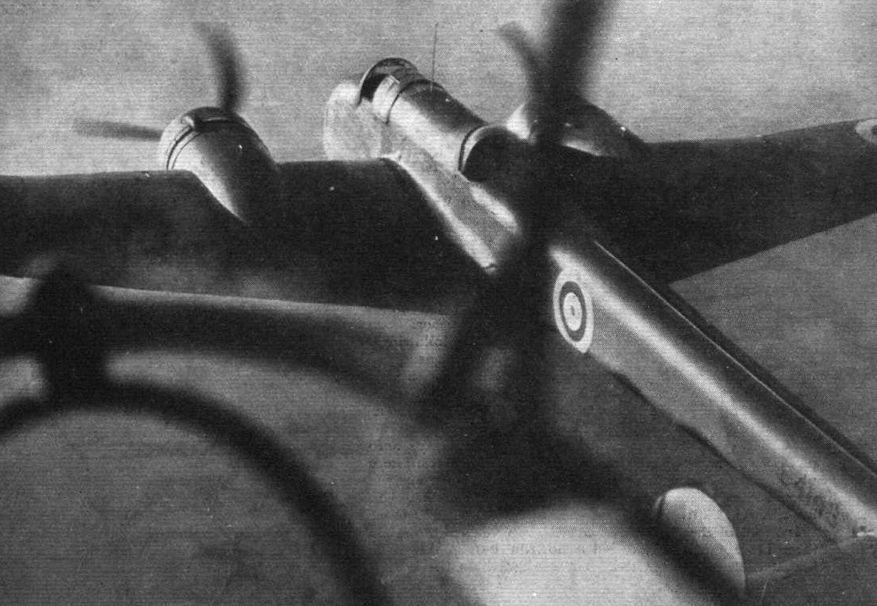
CLOSE-UP: Handley Page Hampden in rather startling proximity to another from which our photograph was taken.
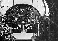
The unimpeded view obtained from the compartment of the front lower gunner and bomber.
INCIDENTS at Hatfield last Tuesday: the H. P. Hampden.
Pegasus XX engines were specified for the Handley Page Hampden prototype shown here. An improved version is in production with Napier E.108s.
K4240 photographed at Martlesham Heath.
Another view of K4240 during one of its visits to Martlesham Heath.
PRESENTED TO HIS MAJESTY. This view of the King studying the retractable undercarriage on the new Handley Page medium bomber during his visit to Martlesham last week is but another illustration of His Majesty's genuine interest in things aeronautical.
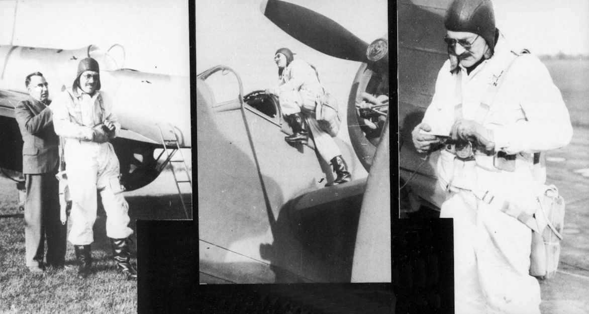
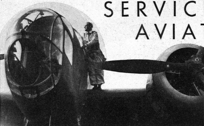
Cape. J. H. Cordes, Chief Test Pilot of Handley Page Ltd., goes aboard a Page Hampden.
The three photographs show Maj Cordes preparing for a test flight in a Hampden at Radlett in 1938. Hampdens were constructed at Cricklewood and assembled and test flown at Radlett.
Handley Page's response to B9/32 was the HP.52 K4240. This entered production as the Hampden.
This view of the prototype H.P. 52 shows the small amount of wing dihedral.
One of outstanding military types of 1936: The Handley Page Hampden.
Handley Page Hampden prototype.
The Handley Page "Hampden" Medium Bomber (two Bristol "Pegasus" engines).
THE REVISED HAMPDEN: Liberal application of slots and flaps combines with clean design and Pegasus engines of the latest series to make the Handley Page Hampden bomber (seen here in its production form) one of the fastest machines of its calibre in the world.
Well defended and able to carry a heavy load at high speed, the Handley Page Hampden, in production for the R.A.A.F., is a brilliant example of the modern twin-engined bomber
SEEING FOR HIMSELF: Mr. W. J. Sanderson, president of Fleet Aircraft of Canada, Ltd., Fort Eerie, Ontario, is an accomplished pilot, and he recently visited the Handley Page aerodrome at Radlett and flew a Hampden. His company, which is one of the manufacturing units of Canadian Associated Aircraft, Ltd., is to build Hampdens.
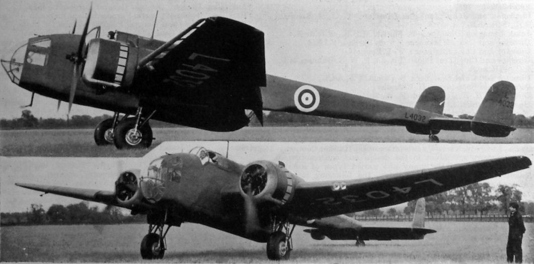
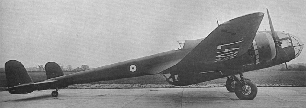
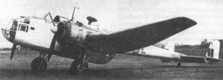
The production prototype Hampden, L4032, was first flown in May 1938. After evaluation by the A&AEE and RAE is was given the Maintenance serial number 2711M in 1941.
Handley Page Hampden I built in Canada and later converted into a torpedo bomber.
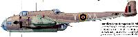
"Хэмпден Mk.I" из состава 106-й эскадрильи. Хорошо виден выпущенный предкрылок
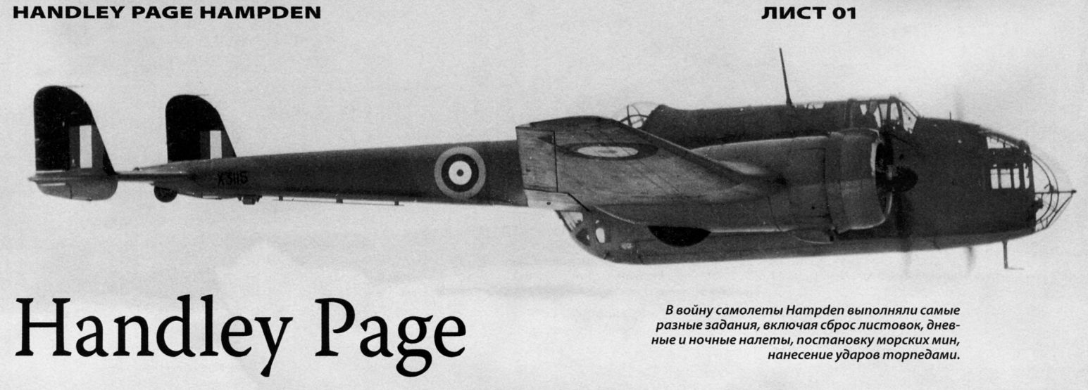
HANDLEY PAGE H.P.62 HAMPDEN II. Published for the first time is a photograph of a Cyclone-powered Hampden II, the H.P.62 - in this case a standard English Electric, Preston-built Hampden, X3115 (in Coastal Command slate- and sea-grey camouflage) which served with No.415 (R.C.A.F.) Squadron from 1940 until permanently grounded in December 1943. This photograph was taken in England in January 1943 and reveals the unpainted, short-chord cowling of the 1,100-h.p. Wright GR1820-G102A 9-cylinder radials which replaced the normal 1,000-h .p . Bri stol Pegasus XVIIIs of the H.P. 52 Hampden I. At one time the Ministry of Aircraft Production had planned to fit Canadian-built Hampdens with Cyclones but the scheme never materialised. Other Cyclone installations included K4032 and and L4032. No other data available.
A few of the Hampdens which are now leaving Radlett aerodrome in a nice steady stream for “unknown destinations.”
Hampden L4080 at Radlett in February 1939. Powered by two 1,000 h.p. Bristol Pegasus XVIII radial engines, nearly 1,400 were built.
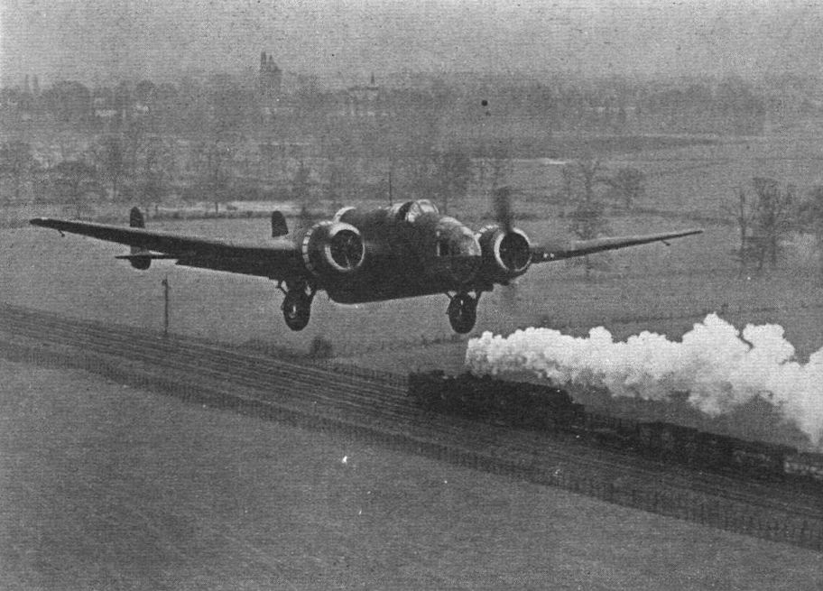
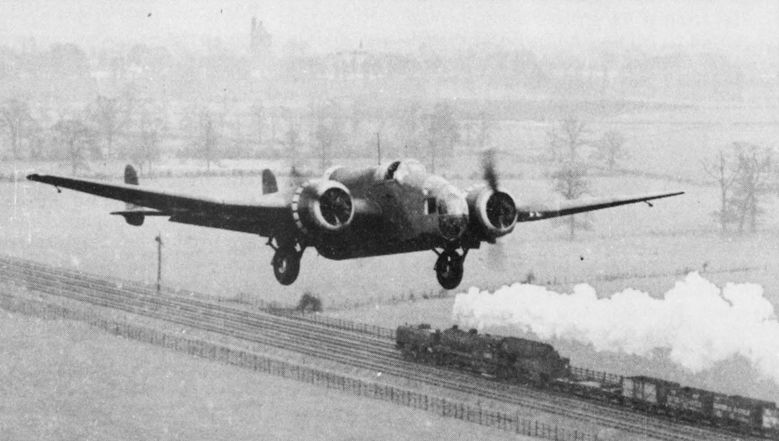
TRACTIVE EFFORT: Capt. J. H. Cordes retracts the undercarriage of a Hampden as he passes - on the L.M.S. line skirting Handley Page’s Radlett Aerodrome - a “Garratt” type locomotive, which is capable of a tractive effort of 45,620 lb. The combined take-off output of the Pegasus engines of the Hampden is between 1,900 and 2,000 h.p.
Cordes flying Hampden L4135 along the railway line at Radlett in April 1939. (First person to write in and tell us what type of locomotive is travelling in the opposite direction will receive a print of the photograph.)
В войну самолеты Hampden выполняли самые разные задания, включая сброс листовок, дневные и ночные налеты, постановку морских мин, нанесение ударов торпедами.
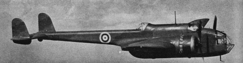
Hampden II with Cyclone engines, distinguished by the short-chord cowlings.
The Handley Page Hampden (two Bristol Pegasus) follows the Harrow as the standard production type at the Handley Page works;
PROBOSCIDAL MODS: The new nose of the Handley Page Hampden bomber (two Pegasus) as now in quantity production. Deliveries will start very shortly. Note the dihedral on the wings and the revised gun position.
The Handley Page "Hampden" Medium Bomber (two Bristol "Pegasus" engines).

THE HANDLEY-PAGE "HAMPDEN": two “Bristol” Pegasus XX engines, with C.P. airscrews. A mid-wing monoplane day and night bomber-fighter of all-metal construction with flush riveting and stressed skin; fitted with the H.P. flapped-and-slotted wing system, giving a wide speed range. Retractable undercarriages and tail-wheel. The crew of four are accommodated in enclosed cockpits giving three gun positions. No details of performance may be given, but manoeuvrability, speed and capacity are notable characteristics. Built by Handley-Page Ltd.
The Handley Page Hampden was the last of the RAF’s twin-engined monoplane bombers to go into service before the outbreak of war. While it had no power-operated gun turrets, it was fast and manoeuvrable with fighter-like handling.
The single-pilot Handley Page Hampden was dubbed “the flying suitcase” by The Aeroplane’s Editor, C.G. Grey owing to its extremely slim fuselage. Interestingly, a German intelligence assessment of the time rated the Hampden as the RAF’s best bomber.
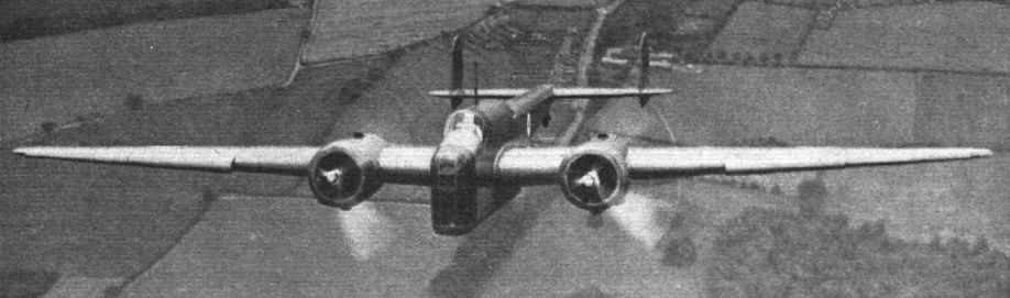
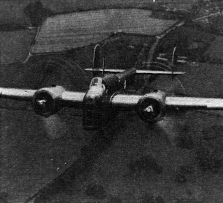
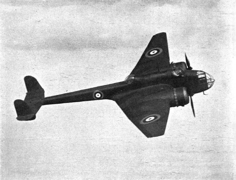
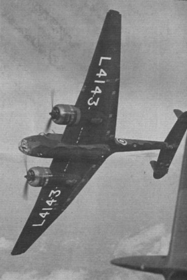
TRAPEZOIDAL: The unusual plan form of the Handley Page Hampden is well brought out in this picture. The machine is now in large-scale production at Cricklewood, where, the makers claim, the new system will “result in a peak rate of production at least twice that of the Harrow for the same floor space.”
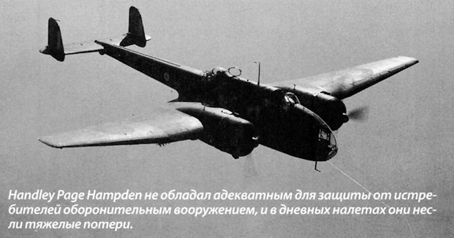
Handley Page Hampden не обладал адекватным для защиты от истребителей оборонительным вооружением, и в дневных налетах они несли тяжелые потери.
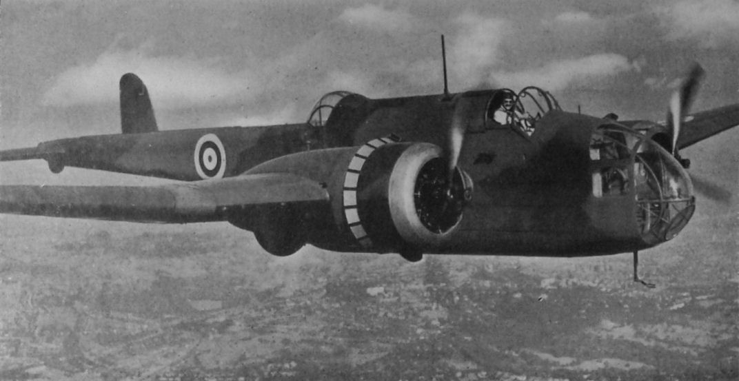
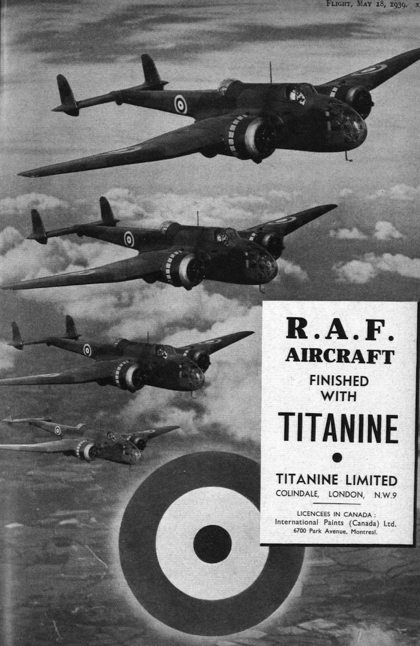
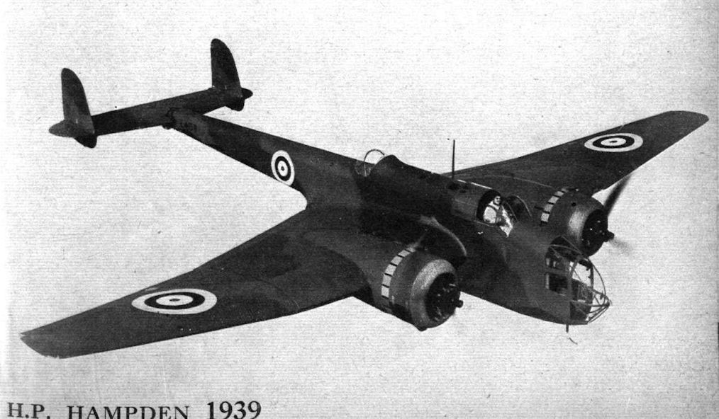
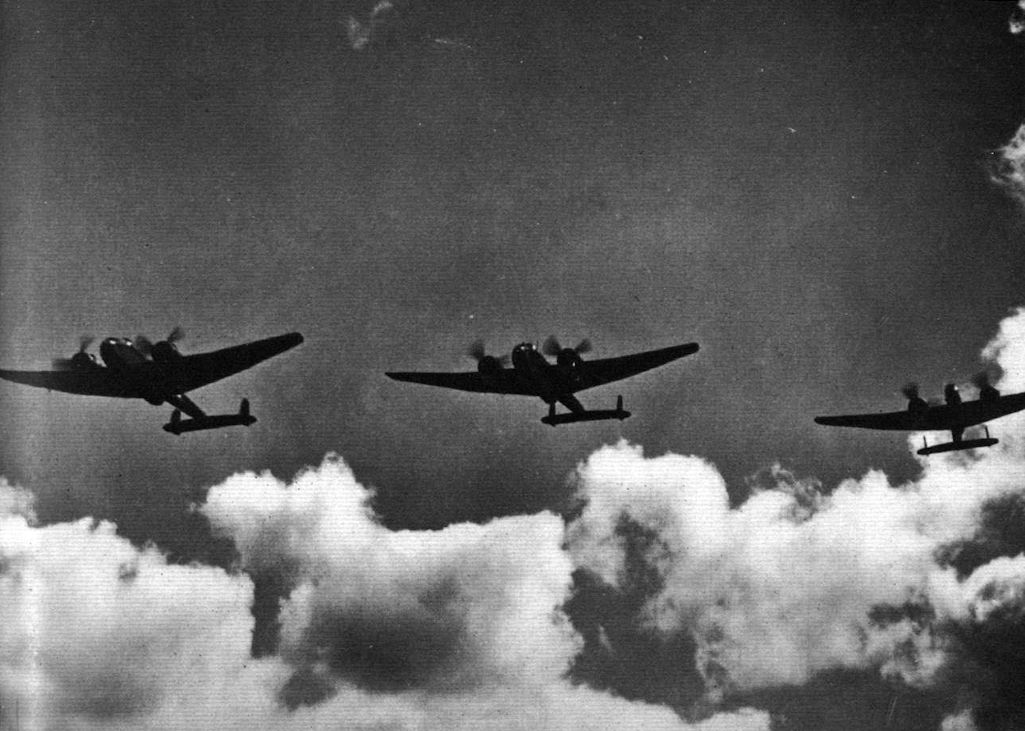
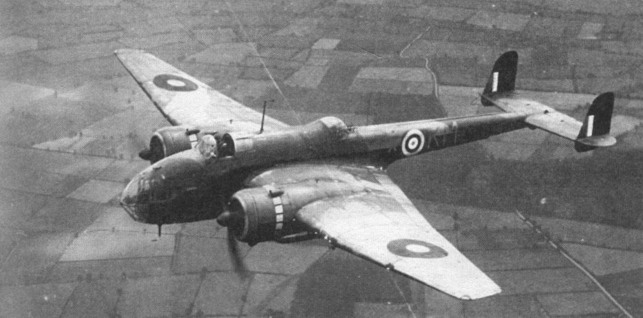
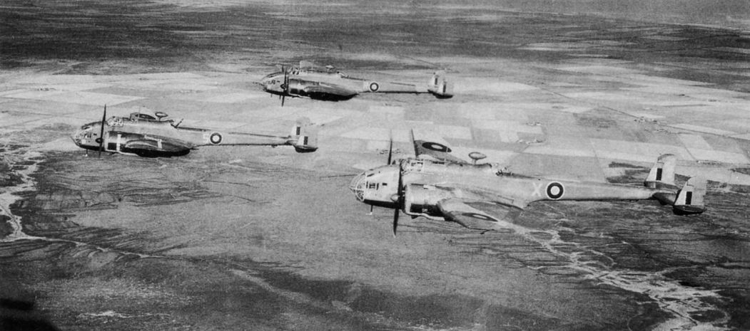
PEGASUS-POWERED: Handley Page Hampden I bombers on a practice flight. The Hampden is powered with two Bristol Pegasus XVIII engines and has a top speed of 265 m.p.h. The armament is four machine guns.
Last of the RAF’s twin-engined bombers to go into service, the Hampden was used extensively during the early part of the war, initially with 49 Sqn. Eight Hampden squadrons were ready on declaration of war in September 1939.
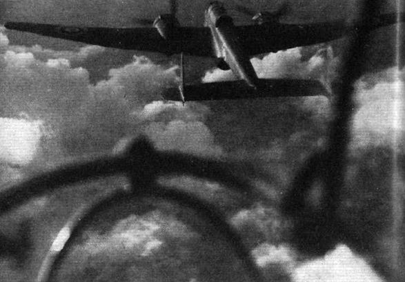
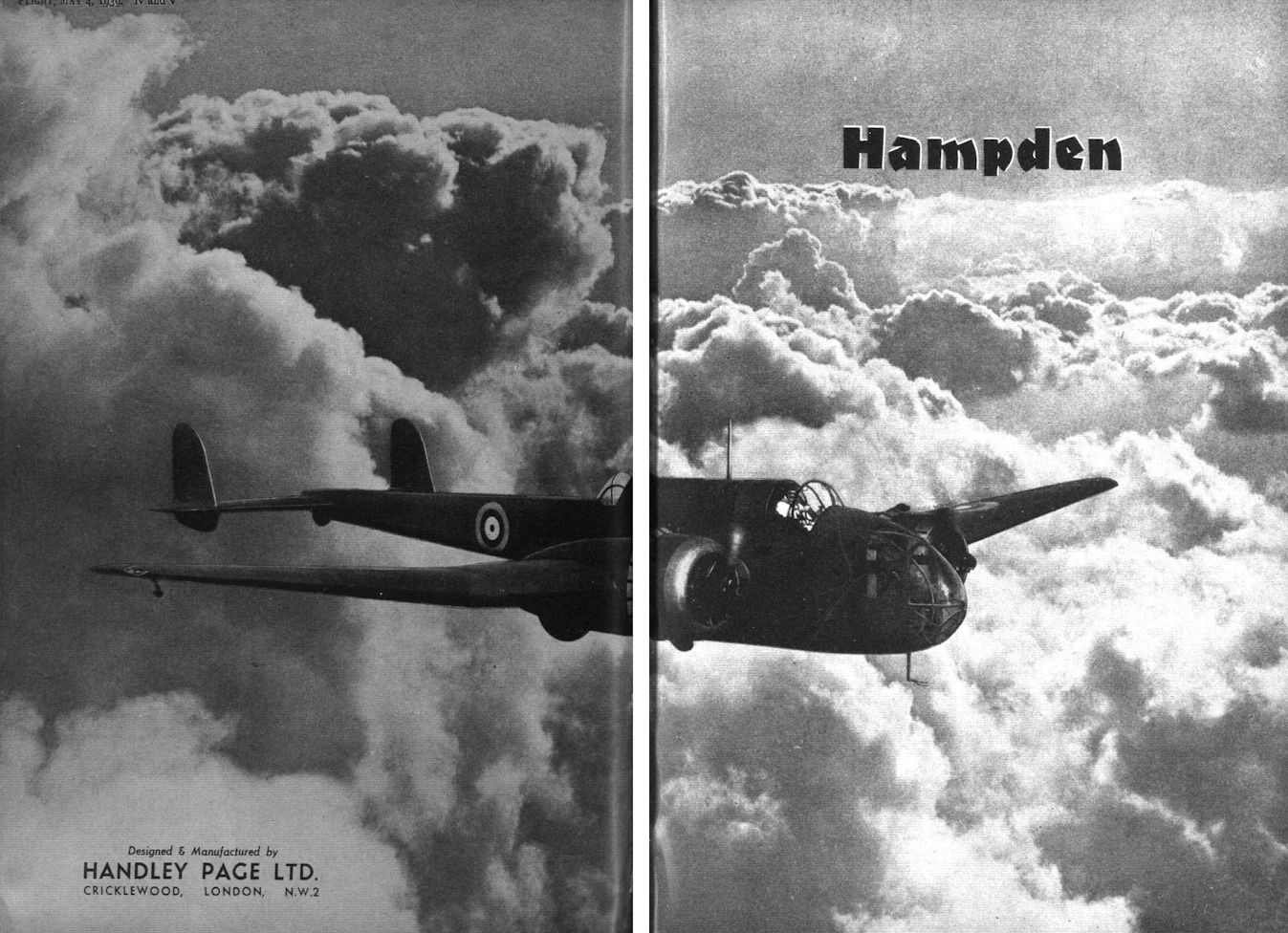
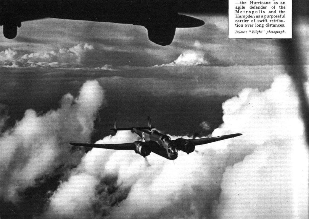
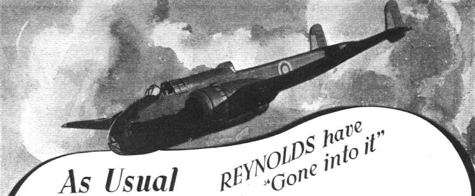
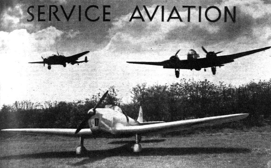
Cloudscape which give an oddly symbolic impression of the duties of the machine depicted - the Hampden as a purposeful carrier of swift retribution over long distances.
STRIKING POWER. Handley Page Hampden bombers of a type which composes a large portion of our bomber force. Although in service in large numbers the Hampden is still among the most efficient bombers in the world.
Last of the twin-engined bombers to go into RAF service during the expansion was the Handley Page Hampden bomber.
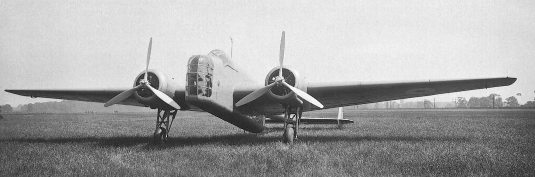
На этой фотографии хорошо видно, каким узким был фюзеляж Hampden, за который самолет и прозвали "The Flying Suitcase".
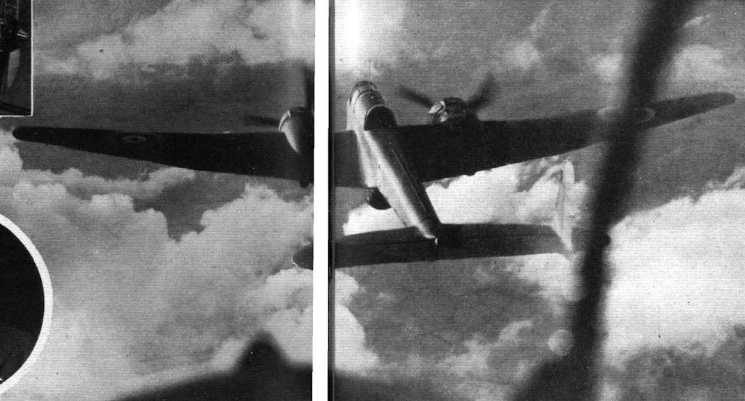
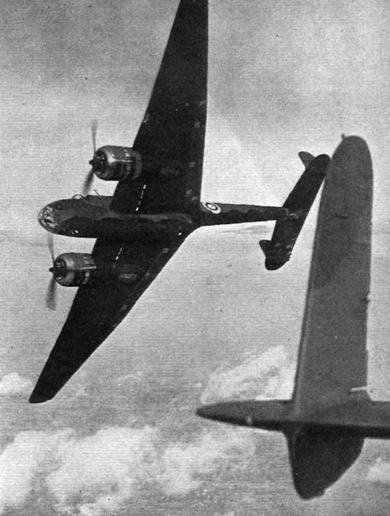
There are two rear gun positions in the Hampden, an upper and a lower. How unhindered are the fields of view and fire obtained from them is shown in the pictures. Major Cordes gives a good illustration of the Hampden as a fighter bomber.
The manoeuvrability and the clear arcs of fire justify the makers in terming the Hampden a fighter bomber. On the occasion depicted, its agility was being demonstrated by Major Cordes. The photographic Hampden was piloted by Flt. Lt. J. R. Talbot.
Maj Cordes displays Hampden I L4143 for Flight’s photographer, 1938.
Handley Page Hampden bombers, which, like the Blenheims, are outstanding examples of the work of an old-established manufacturer.
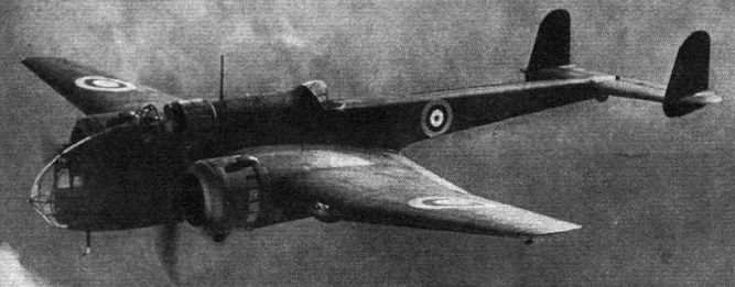
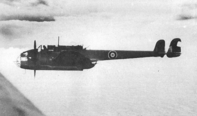
Бомбардировщик "Хэмпден" I в полете
Development: The production version of the Hampden, a bomber of outstanding merit.
Fitted with two Bristol Pegasus XVIII engines the Handley Page Hampden bomber has a top speed 265 m.p.h. It is armed with four machine guns.
"Хэмпден" I из 44-й эскадрильи британских ВВС, 1940 г.
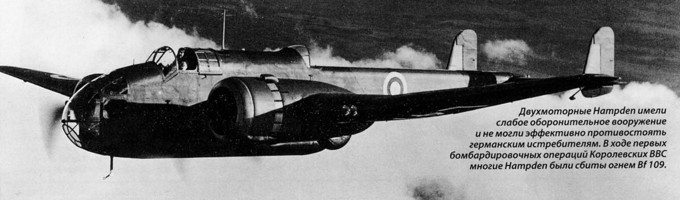
Двухмоторные Hampden имели слабое оборонительное вооружение и не могли эффективно противостоять германским истребителям. Входе первых бомбардировочных операций Королевских ВВС многие Hampden были сбиты огнем Bf 109.
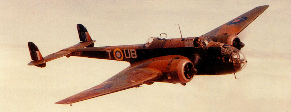
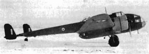
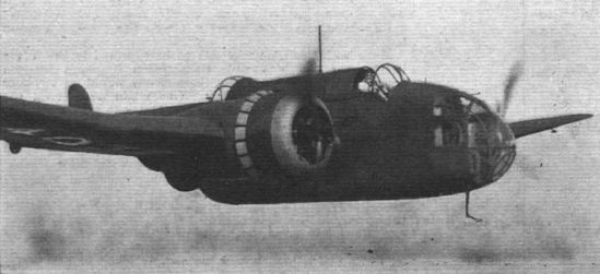
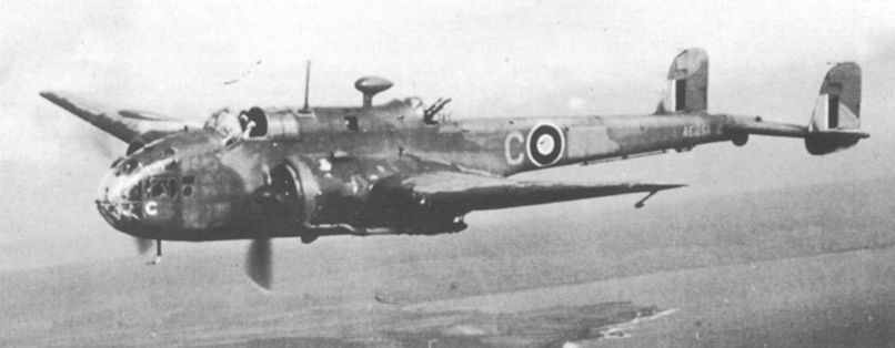
This Hampden is seen returning from a mission off the Norwegian coast with much of the port rudder shot away by flak - winter 1942-43.
185-я эскадрилья, входившая в состав 5-й группы Бомбардировочного командования, использовала бомбардировщики Hampden (на снимке) и одно звено ненадежных Hereford с моторами Dagger. Номинально эта часть считалась учебной.
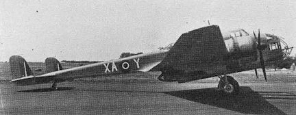
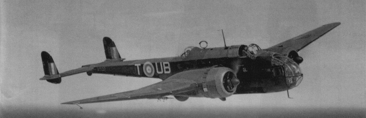
Новозеландская 489-я эскадрилья летала на торпедоносцах-бомбардировщиках Hampden из Льючерза с марта 1942 года по декабрь 1943 года.
Hampden TB Mk 1 in service with RNZAF-manned No 489 Sqn, in 1942. The code letters XA appear to have been overpainted.
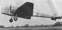
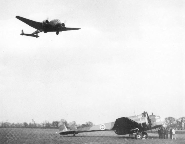
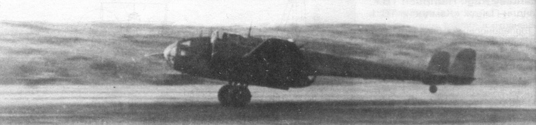
LOW APPROACH: Thanks to its slots and flaps the Handley Page Hampden can be operated from small aerodromes. A pair of Hampdens are seen approaching low with a Miles Magister in the foreground.
Controllability is but one of the many strong points of the Hampden. Here Major Cordes shows it “formating” at 65 m.p.h. with wheels and flaps down.
A Hampden 1 bearing the prewar codes of No 66 Sqn at RAF Waddington.
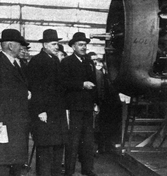
CAPT. BALFOUR, Under-Secretary for Air, sees Hampdens in production. On the right is Mr. Handley Page and on the left Rear-Admiral Sir Murray Sueter.
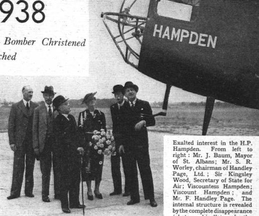
Exalted interest in the H.P. Hampden. From left to right : Mr. J. Baum, Mayor of St. Albans; Mr. S. R. Worley, chairman of Handley Page, Ltd. ; Sir Kingsley Wood, Secretary of State for Air; Viscountess Hampden; Viscount Hampden; and Mr. F. Handley Page. The internal structure is revealed by the complete disappearance (photographically) of the moulded Perspex windows.
The Handley Page Hampden medium bomber (two Bristol Pegasus) posing for its portrait after last Friday's ceremony.
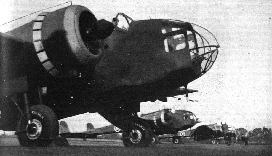
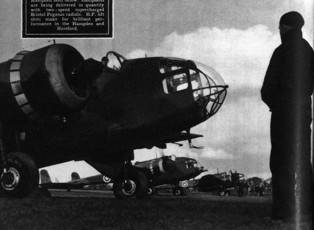
Hampdens being delivered in quantity with two-speed supercharged Bristol Pegasus radials. H.P. lift slots make for brilliant performance in the Hampden and Hereford.
Боевой дух личного состава Бомбардировочного командования в начале войны сильно упал из-за тяжелых потерь, понесенных в дневных налетах.
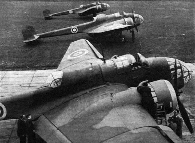
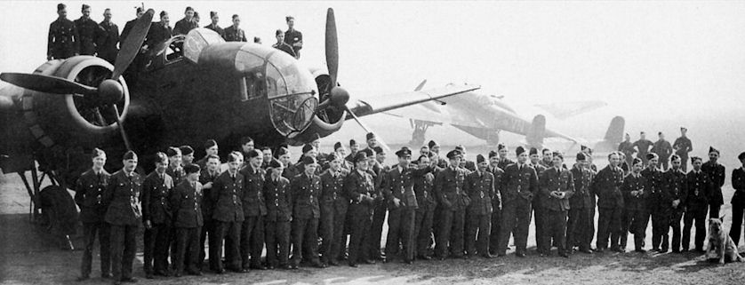
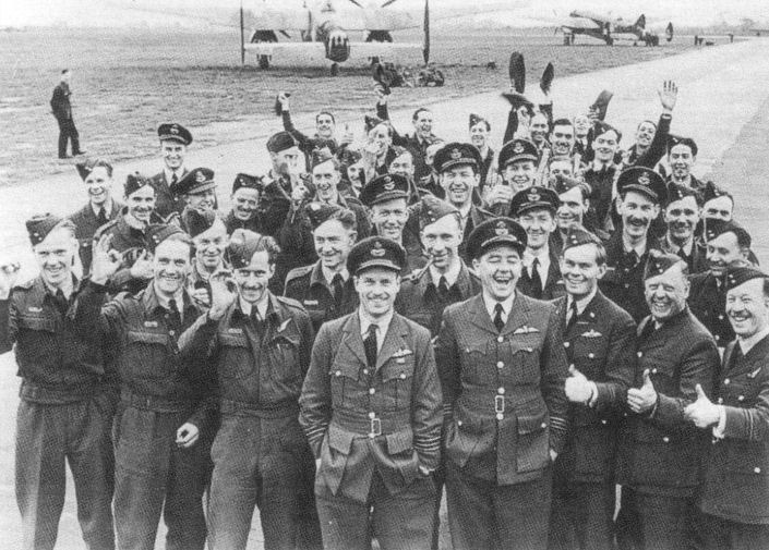
Летный состав 106-й эскадрильи 5-й авиагруппы Бомбардировочного Командования вместе со своим командиром уинг коммандером Гаем П.Гибсоном (на снимке стоит впереди всех) позирует после успешно проведенных ночных вылетов. На заднем плане видны бомбардировщики "Хэмпден" (слева) и "Манчестер" (справа). Судя по всему, фото сделано в период между февралем и маем 1942г., когда 106-я эскадрилья осваивала самолеты последнего типа. Уже в мае она начала оснащаться четырехмоторными "Ланкастерами Mk.IB". Авиабаза Конигсби.
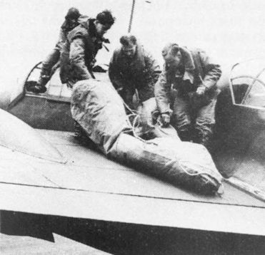
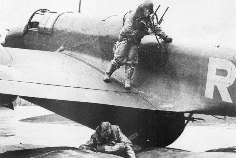
A Hampden crew practise emergency ditching procedure with the dinghy on the wing.
The pilot about to jump into the inflated dinghy.
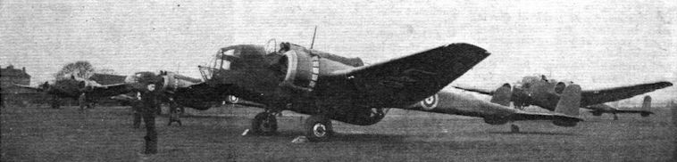
HAMPDENS about to leave their makers aerodrome for delivery to squadrons.
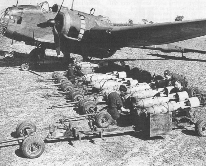
Hampden I P1333 being bombed up in 1940. The maximum bomb load was 4,000 lb. P1333 served with 49 Squadron and went missing on August 17, 1940. It was one of a batch of 200 Hampden Is delivered to the RAF between June 1939 and February 1940.
"Хэмпден" TB.I из 521-й эскадрильи Берегового командования, аэродром Докинг
Торпедоносец "Хэмпден" из 3-й эскадрильи 9-го МТАП перед боевым вылетом. 5 мая 1943г.
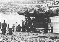
Торпеду Mk XII готовят к подвеске на "Хэмпден" TB1. 24-й мтап, Северный флот. Конец 1942 года.
Английские "Хэмпдены" оказались плохо приспособлены для эксплуатации в суровых условиях Заполярья, а с учетом неважных пилотажных характеристик, оценивались пилотами советской минно-торпедной авиации существенно ниже отечественных Ил-4.
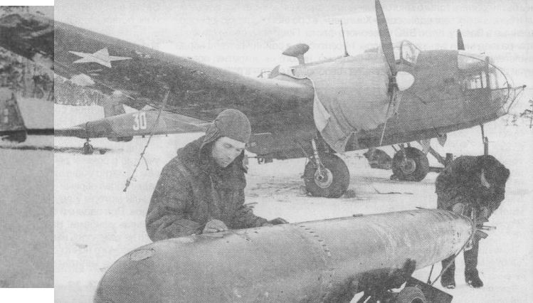
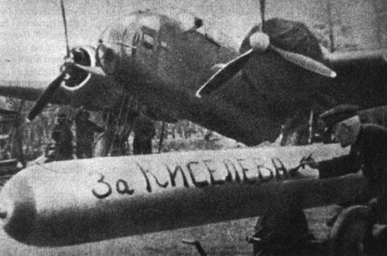
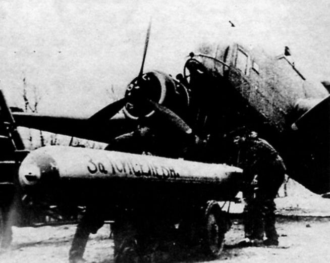
One of the 23 Hampden TB Mk Is that passed into service with the Soviet Navy’s air arm in 1942.
This photograph shows a Hampden in service with 24 PLMT in the Soviet Union. The inscription on the torpedo reads "For Kisyelev".
25 апреля 1943 года в атаке на немецкий конвой геройски погиб экипаж торпедоносца "Хэмпден" под командованием капитана В.Н.Киселева. В ряде изданий указывается, что летчики совершили "огненный таран", потопив немецкий транспорт "Леезее". По другим, более достоверным данным транспорт был потоплен торпедой.
Подвеска торпеды под один из самолетов 24-го мтап, май 1943г.
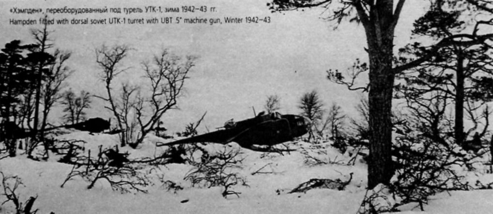
"Хэмпден", переоборудованный под турель УТК-1, зима 1942-43гг.
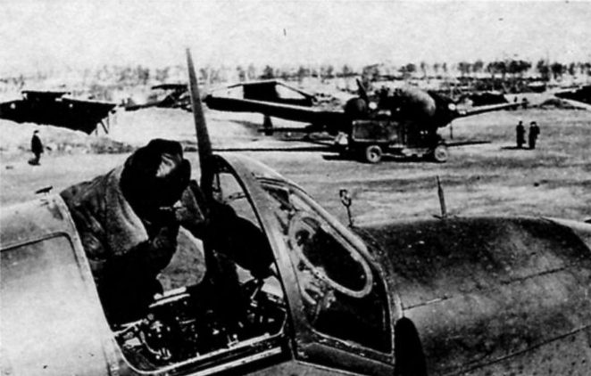
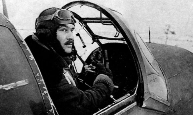
Гвардии капитан А.Стоянов в кабине своего самолета.
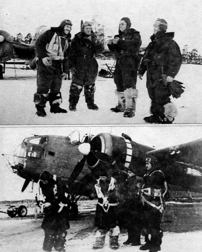
Экипаж командира 2-й эскадрильи 24-го МТАП ВВС СФ А.З.Стоянова перед боевым вылетом у своего "Хэмпдена", аэродром Ваенга (под Мурманском). 1942г.
А.Стоянов (первый слева, на фото снизу - первый справа) со своим экипажем: к-н Коровинский (штурман), с-т Ковтун (стрелок), ст.с-т Зайцев (радист).
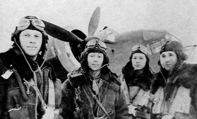
Экипаж, одержавший первую победу на английском торпедоносце. Капитан С.Трунов (первый слева) со своим экипажем: ст.с-т Черных (штурман), с-т Камнин, с-т Гортованный.
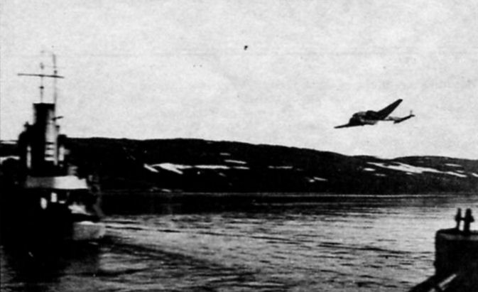
Один из самолетов 24-го полка на посадке в Ваенге
Production flow. These pictures illustrate the sequence of operations in building the Hampden fuselage. (1) The skeleton of the nose portion being assembled ; (2) after removal to a jig, the skin is riveted on; (3) installing equipment in the starboard half of the centre portion; (4) assembling the two halves of the centre portion in a special jig; (5) the two halves of the fuselage tail portion are built on horizontal jigs, although the split is vertical; (6) the three fuselage portions being brought together for assembly before transport to Radlett. The transparent nose unit is not yet in place.
Growing wings: (1) the Hampden main spar in a horizontal drilling jig; (2) the spar in the assembly jig, where it forms the basis of the whole centre-section; (3) an outer wing having covering finished and ailerons attached; (4) assembling centre and outer wing portions before dismantling them for transport to Radlett; (5) installing leads and engine controls on front wall of spar box; (6) assembling trailing-edge portions in their jigs; (7) the engine installation jigs also have provision for assembling the undercarriage fully extended.
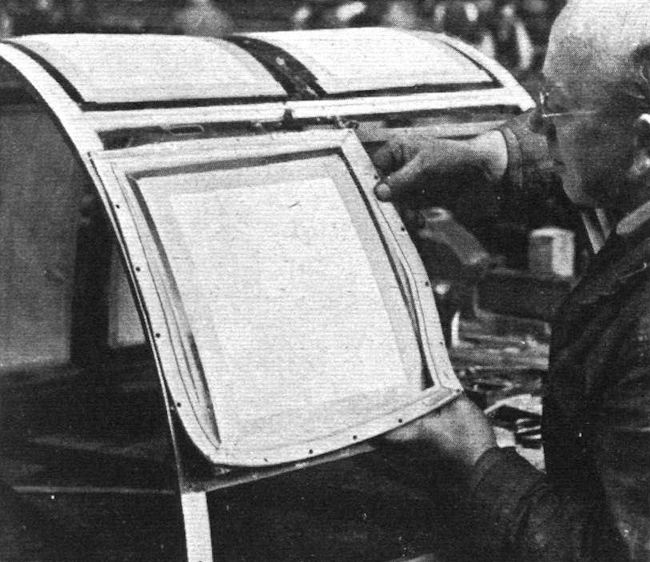
INSTALLING “LINATEX” KNOCK-OUT WINDOWS ON THE HAMPDEN.
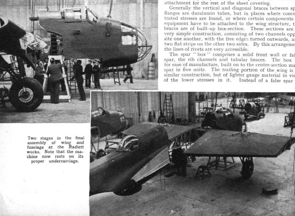
Two stages in the final assembly of wing and fuselage at the Radlett works. Note that the machine now rests on its proper undercarriage.
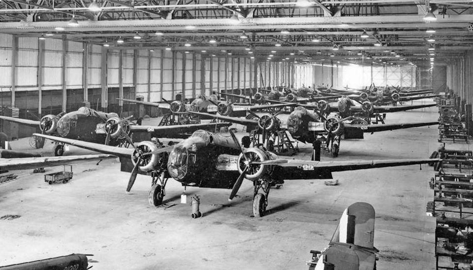
Hampdens under construction at Radlett in April 1939.
In the wake of the Munich Agreement production of bombers for the RAF was ramped up. One of the more promising new designs was the Handley Page Hampden, which was fast, manoeuvrable and could carry a bomb-load of 4,000lb (1,825kg). The Hampden bore the brunt of Bomber Command’s early wartime raids over Germany.
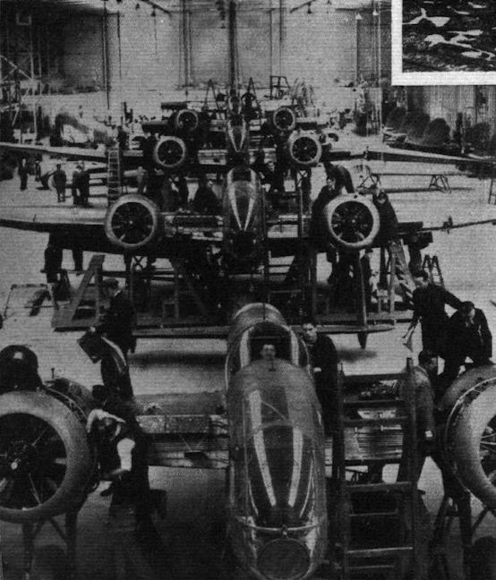
Bomber production: H.P. Hampdens, capable of 265 m.p.h., seen in the final assembly stage at the assembly plant at Radlett. The Hampden has two Bristol Pegasus XVIII engines with two-speed superchargers.


 Wikipedia