 Wiki
Wiki Фотографии
-

-

-

Aviation Historian 27 / J.-C.Carbonel - Messieurs Papin et Rouilly's Astonishing Whirling Leaf
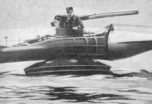
In June 1914 the Gyroptere arrived at Lake Cercey, where it was manhandled into the water using a specially constructed wharf and crane. Here a uniformed Papin is seen in the gondola before the rowing boat behind him is used to tow the unwieldy contraption out to the middle of the lake for testing. Note one of the oil tanks added to the violin.
-

Aviation Historian 27 / J.-C.Carbonel - Messieurs Papin et Rouilly's Astonishing Whirling Leaf
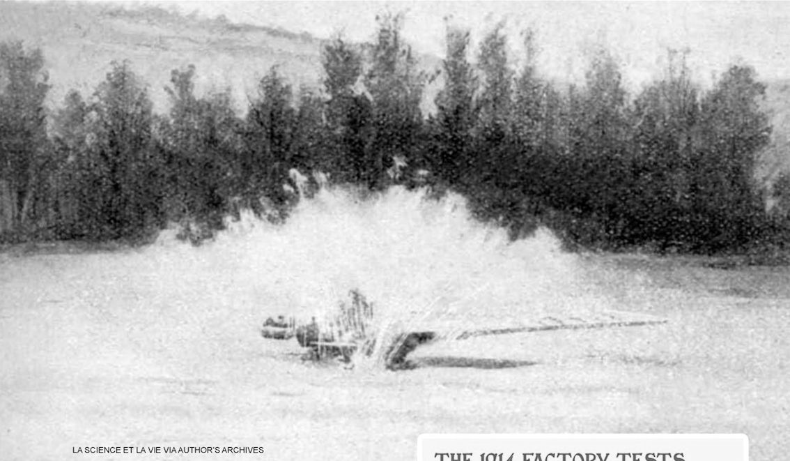
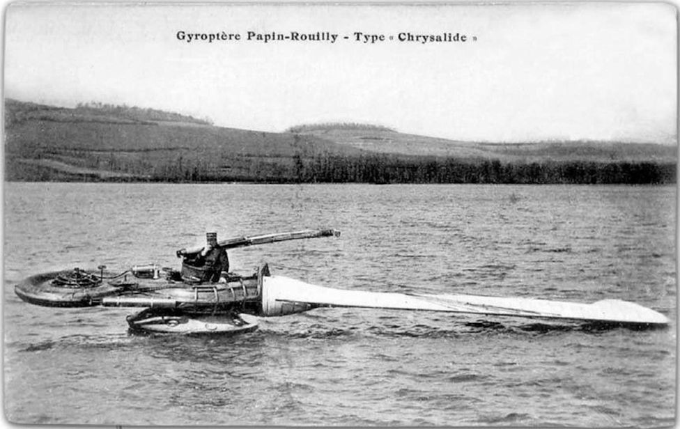
This very poor-quality and heavily retouched image displays much thrashing about with little to show for it, probably taken during the attempt on March 31, 1915, to fly the Gyroptere. With so much spray, it is impossible to determine whether the machine is actually in the process of lifting itself clear of the lake’s surface - naturally, Papin claimed it was.
-

Aviation Historian 27 / J.-C.Carbonel - Messieurs Papin et Rouilly's Astonishing Whirling Leaf
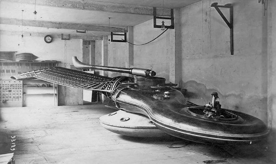
In the conspicuously tidy Gremont workshop, the completed and assembled Gyroptere awaits its move from to Lake Cercey in eastern France. Note the distinctive “antenna” fitted to the central gondola, to be fed with compressed air bled from the fan and used for directional control in place of a conventional rudder arrangement.
-

Aviation Historian 27 / J.-C.Carbonel - Messieurs Papin et Rouilly's Astonishing Whirling Leaf
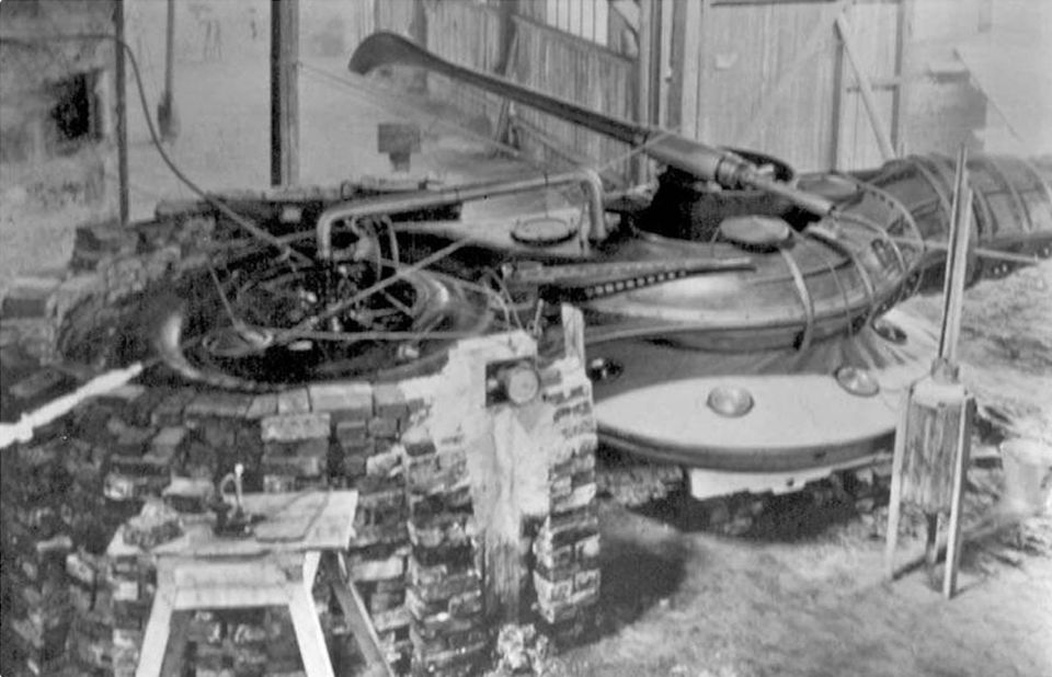
Looking like something from H.G. Wells’s novel The Time Machine, the finished Gyroptere has been taken outside the workshop for engine runs in a brick-built circular test rig. Note the piping connecting the engine and the main body - no details survive about what this is, although it may be a primitive form of turbocharging.
-

Aviation Historian 27 / J.-C.Carbonel - Messieurs Papin et Rouilly's Astonishing Whirling Leaf
Technicians get to work on the Gyroptere’s massive single wing in the Gremont workshops in 1913. Although Papin and Rouilly’s concept was radical in many respects, Englishman W.H. Phillips had flown a jet-powered experimental model helicopter (with revolving fans) actuated by gas-charged steam as far back as 1842.
-

Aviation Historian 27 / J.-C.Carbonel - Messieurs Papin et Rouilly's Astonishing Whirling Leaf
Another view of the Gremont workshop in Paris, where work is being undertaken on the wooden “violin” section of the Gyroptere in 1913. The elegant curved shape of this section would have called for a high level of craftsmanship from the carpenters employed on the project.
-

Aviation Historian 27 / J.-C.Carbonel - Messieurs Papin et Rouilly's Astonishing Whirling Leaf
Messieurs Papin and Rouilly continued their studies into gyroptere-style aircraft after the end of the Great War. Their final three-dimensional design was this model of a two-bladed gyroptere with tipjets working on the aeolipile principle, seen during windtunnel testing at the Laboratoire Aerodynamique Eiffel in Paris.
-

Aviation Historian 27 / J.-C.Carbonel - Messieurs Papin et Rouilly's Astonishing Whirling Leaf
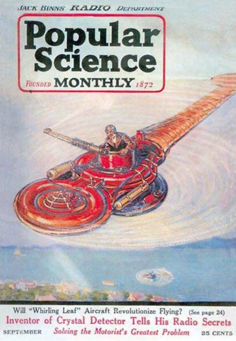
A somewhat fanciful artist’s impression of a vivid scarlet Gyroptere appeared on the cover of the September 1922 issue of American magazine Popular Science Monthly, which carried an article entitled Will This “Whirling Leaf” Flying Machine Solve Greatest Problem in Aviation? Unfortunately for Papin and Rouilly, the answer proved to be a resounding no!
-

-

Aviation Historian 27 / J.-C.Carbonel - Messieurs Papin et Rouilly's Astonishing Whirling Leaf
Complete with behatted pilot, these drawings relating to French Patent No 440594 show the workings of Papin and Rouilly’s original concept for a single-winged helicopter to be operated on the aeolipile principle. Although differing substantially from the Gyroptere as finally built, these show the same essential layout, with a central gondola and rotating wing and engine housing.
-

Aviation Historian 27 / J.-C.Carbonel - Messieurs Papin et Rouilly's Astonishing Whirling Leaf
Contemporary diagram of the Gyroptere as built, from French science magazine La Science et la Vie, showing the various constituent parts of the contraption. A = hollow wing; B = 80 h.p. le Rhone rotary engine; C = turbine fan; D = gondola “rollers”; E = central “violin”; F= “antenna“ for directional control; G = antenna nozzle; H = wing nozzle; I = hollow float; J = gondola.
-

Aviation Historian 27 / J.-C.Carbonel - Messieurs Papin et Rouilly's Astonishing Whirling Leaf
This 1920s sketch by Didier Rouilly shows another concept for a gyroptere, this time a symmetrical (twin-rotor) version for two crew members positioned in a prone position (“position allongee”) on a bench arrangement situated within a “cage” sandwiched between the float and the rotor assembly. The motor was to be housed at the top of the machine, above the rotors. It would not have been for the faint-hearted!
-

Aviation Historian 27 / J.-C.Carbonel - Messieurs Papin et Rouilly's Astonishing Whirling Leaf
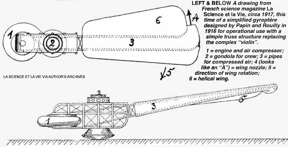
A drawing from French science magazine La Science et la Vie, circa 1917, this time of a simplified gyroptere designed by Papin and Rouilly in 1916 for operational use with a simple truss structure replacing the complex “violin”. 1 = engine and air compressor; 2 = gondola for crew; 3 = pipes for compressed air; 4 (looks like an “A”) = wing nozzle; 5 = direction of wing rotation; 6 = helical wing.