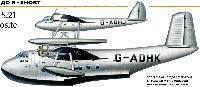
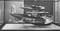
Mayo Composite (S.20 Mercury and S.21 Maia)
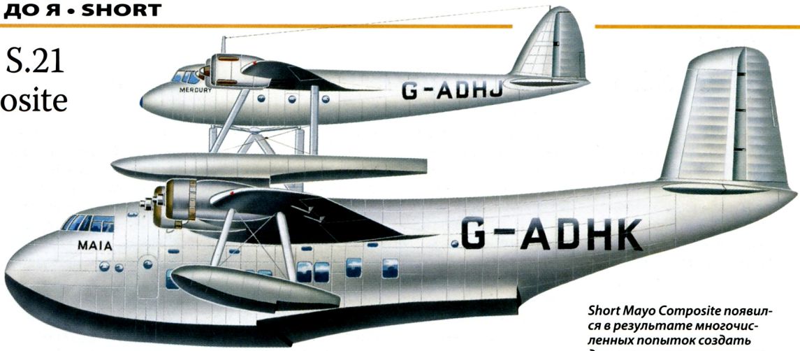
Short S.20 и S.21 Mayo Composite
В результате проведенных авиакомпанией "Imperial Airways" испытаний было установлено, что летающая лодка Empire может достичь трансатлантической дальности полета только в том случае, если будет полностью ДальшеMore>>>
загружена топливом. Однако специалисты знали, что самолет может совершать полет с большим весом, чем тот, с которым он может взлететь. Тогда майор Роберт Мэйо, генеральный технический менеджер "Imperial Airways", предложил выводить небольшой сильно перегруженный почтовый самолет на рабочую высоту на большой авиаматке, а затем освобождать его. Предложение было принято министерством авиации и "Imperial Airways", которые заключили контракт с компанией "Short Brothers" на проектирование и постройку такой составной конструкции.
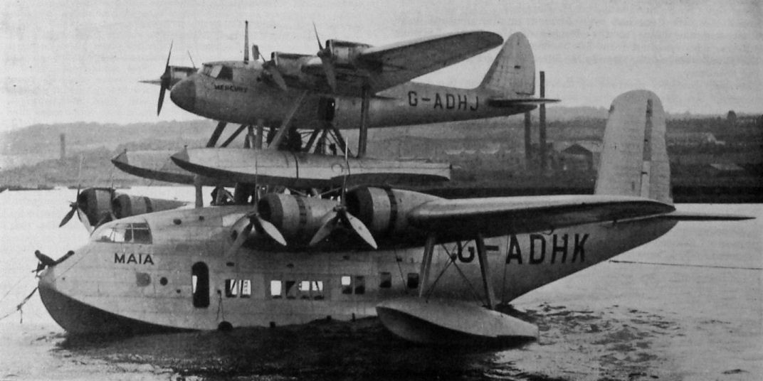
Авиаматка S.21 Maia являлась слегка увеличенным и модифицированным вариантом летающей лодки Empire. Но самолет S.20 Mercury, который располагался над авиаматкой, являлся новым. Это был гидросамолет с высокорасположенным крылом и двумя поплавками, оснащенный четырьмя двигателями Napier Rapier H мощностью 340 л. с., которые обеспечивали крейсерскую дальность 6116 км с почтой массой 454 кг.
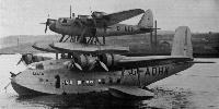
Первое разделение с авиаматкой в воздухе было выполнено 6 февраля 1938 года. После ряда экспериментальных полетов 21 июля самолет Mercury был запущен с авиаматки над городом Фойнс, Ирландия, и за 20 часов 20 минут совершил перелет протяженностью 4715 км в Монреаль, имея полезную нагрузку 272 кг.
6 октября 1938 года самолет Mercury стартовал над городом Данди, чтобы установить до сих пор непревзойденный международный рекорд дальности беспосадочного перелета для гидросамолетов в 9652 км, который он выполнил до реки Оранжевая в Южной Африке. Однако начало войны положило конец подобным экспериментам. Mercury разбился в Рочестере, a Maia был уничтожен немцами в мае 1941 года.
Flight, February 1938
SHORT MAYO
The Composite Aircraft Described in Detail
THE successful separation flight of the Short-Mayo composite aircraft, recorded in Flight last week, has once more focused attention on one of the most interesting technical experiments made for many years, and has made it possible to publish a detailed description of the aircraft built by Short Brothers, of Rochester, to test out Major R. H. Mayo’s theories.
As there is still a good deal of mis-conception of the fundamental principles involved, it may be useful to examine them again briefly. Readers who wish to study the subject more thoroughly are advised to refer to their copies of Flight of November 7 and 14, 1935, in which the Editor explained in simple language the objects and methods of the system.
First of all, it should be pointed out that the raison d'etre of the composite is to extend the range of an aircraft by assisting it into the air with a greater load than that which it could lift into the air under its own power. Once an aircraft is flying, it needs less power to support itself in flight than that required to take off.
In the Mayo scheme a large but lightly loaded flying boat is used for carrying on its back a much smaller but very heavily loaded floatplane and helping it into the air. When the desired height has been reached the two aircraft separate, the smaller proceeding on its journey and the larger returning to its base.
One of the mistakes most commonly made is to think that at the moment of separation the lower component, relieved of the weight of the upper, will tend to rise suddenly, while the upper component, suddenly compelled to carry the whole of its own weight, will tend to drop. If that were the case, the operation would indeed be a dangerous one. Actually, the very opposite is the case; the lower component tends to drop and the upper tends to rise, thus automatically providing the force needed to separate the two. It is, perhaps, the realisation of this fact for which Major Mayo deserves the greatest credit. How it is achieved needs a little explanation, starting with basic principles.
Many of Flight's readers will be aware that the lift of an aeroplane wing is represented by a curve of lift coefficients plotted against angles of incidence. From the small angle of no lift to the angle of maximum lift the curve is almost a straight line. At the angle of maximum lift the curve turns into a horizontal direction, and then begins to drop again, showing that maximum lift has been exceeded and the wing has begun to stall.
This general shape of lift curve is common to all wing sections, but the values of the lift at the different angles of incidence vary with the type of section used. The secret of the Mayo scheme lies in choosing the two wing sections in such a way that the lift curve of the upper wing is an "envelope" curve, i.e., that at all angles of incidence it is outside the curve of the lower wing. If that is done, the lower wing, or rather the wing of the lower component, will stall before that of the upper component.
From the lift curves of the two wings it is possible to plot a graph in which the lift of each wing is shown against speed. Here it should be explained that at small angles of incidence the lift is smaller, and it is necessary to fly at higher speed in order to get the lift. The curves on the preceding page bear no direct relationship to the actual Short-Mayo composite, as the two wing sections used as a basis for the calculations are quite different from those of the Maia and Mercury. One result is that they show a rather lower "separation speed" than that of the actual machines. The principle is, however, exactly the same.
It will be seen from the curves that at low speeds, i.e., just after the take-off, the lower component carries far more of the weight than the upper. As speed increases, the upper component carries more and more and the lower less and less of the weight. At a speed of about 156 m.p.h. in the example chosen (which, as already explained, does not correspond exactly with the figures of the actual machines) the two curves cross over one another. At that speed, therefore, the total lift is equally divided between the two machines. If both are of the same weight that speed will therefore be the one at which each carries its own weight. At any higher speed there will obviously be a separating force tending to pull the two machines apart. The weights of the two actual machines are not equal. The lower component weighs about 27,500 lb., and the upper weighed, at the time of the first separation flight, about 14,500 lb. From the curves this would mean that at about 90 m.p.h. each machine was carrying its own weight, and that at any higher speed there would be a separating force; but again it should be emphasised that the curves were based upon assumed and not upon actual data, and that therefore the example should be accepted merely as showing the principle involved.
Turning from the general to the specific case, the Short-Mayo composite aircraft comprises (a) a large four-engined flying boat, generally similar to, but with a slightly larger wing area than, the Empire boats, and (b) an upper component in the form of a four-engined twin-float seaplane. As Maia, the lower component, shows exactly the same structural features as the Empire boats, a description of which was published in Flight of October 29, 1936, it will suffice if it is pointed out here that the main changes are an increase in the wing area (from 1.500 sq. ft. to 1.750 sq. ft.), an increase in the beam of the hull over the chines, and slightly larger outboard floats, set rather lower in relation to the water line so as to prevent the craft from heeling over. The ailerons are also larger in order to give sufficient control for the composite during the time when the controls of the upper component are locked. The engines of the Maia are, as in the Empire flying boats, four Bristol Pegasus Xc, which give a maximum output of 875 - 915 b.h.p. at 2,600 r.p.m. at 6,250ft., a normal output of 810 - 850 b.h.p. at 2,250 r.p.m. at 4,000ft., and a take-off power of 920 - 960 b.h.p. at 2,475 r.p.m. The engines are housed in long N.A.C.A. cowlings with controllable-flap gill cooling. They drive De Havilland three-bladed controllable-pitch airscrews. When not used as part of the composite aircraft Maia can be employed as a normal commercial flying boat.
Mercury, the upper component, is a very interesting machine, apart from its functions as part of the composite aircraft. It is an all-metal twin-float seaplane, of the high-wing cantilever monoplane type. The fuselage has been kept down to a small cross-sectional area in order to get the best possible efficiency, and this has been made possible by the fact that the machine, is intended to carry mails only and no passengers. The crew consists of pilot and navigator radio-operator.
The fuselage differs in shape from, but is similar in structural features to, a flying boat hull. That is to say, it has frames and stringers of usual Short type, and the Alclad plating is joggled and flush-riveted so as to form a perfectly smooth surface. The wing root is very neatly faired into the fuselage top, as some of our structural sketches show.
Fundamentally, the wing construction is similar to that of the Empire boats, that is to say, the box spar is made up of corners of extruded T-section tied together by vertical and diagonal tubular struts, the fork-ends of which bolt to the single limbs of the T-sections. However, owing to the fact that the petrol tank arrangement is different, certain changes have been introduced. The 1,200-gallon tank consists of a single cylindrical member, "bent" in the centre to allow for the dihedral angle of the wings. At intervals the tank has diaphragms to prevent the petrol from surging, and flap valves are arranged to open inwards, so that petrol can flow from the outer ends of the tank towards the centre, but not from the centre outwards. Otherwise the fuel might run into the outer portion on one side and cause the machine to capsize. The tank is attached to the wing spar at the diaphragm points, and contributes some thing to the wing strength, particularly to torsional strength.
Although the theory is that most of the fuel will be consumed when the machine has to alight, provision has to be made, for the event of alighting before any considerable quantity of fuel has been consumed. This emergency has been guarded against by fitting jettison valves in the centre of the tank From these valves a pipe runs down through the fuselage, and has its lower end projecting slightly beyond the bottom covering, so that the petrol is carried clear. As the point of emergence is below and several feet aft of the engine exhaust pipes, the chances of the fuel catching fire are extremely remote.
Power for Mercury is supplied by four Napier-Halford Rapier engines of the Mark V type. These are air-cooled, with the sixteen cylinders arranged in the form of a letter H, as seen from in front. Each engine gives a maximum output of 340 b.h.p. at 4,000 r.p.m. at 13,000ft., and a normal output of 315 b.h.p. at 3,500 r.p.m. at 10,000ft They drive two-bladed wooden airscrews.
The floats of Mercury are of usual Short shape and construction. Their displacement is not sufficient to support the machine at the fully loaded assisted take-off weight of 20,500 lb. The maximum permissible gross weight which the floats will support is about 14,500 lb., which is the maximum weight at which Mercury will take off under its own power.
Full performance figures have not yet been obtained, but from the tests made so far it is estimated that the
a range of Mercury will be 3,750 miles when carrying a mail load of 1,000 lb. at a cruising speed of 175 - 180 m.p.h. If this figure is attained it would mean the ability to cross the North Atlantic against an average headwind of 80 m.p.h. Mercury has a wing span of 73 ft. and a wing area of 611 sq. ft., so that at the maximum gross weight the wing loading will be 33.0 lb./sq. ft. The power loading, based on the normal power of 4x315 b.h.p., will be 16.25 lb./h.p.
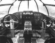
Naturally the accommodation on board Mercury is some what limited. The pilot occupies a seat in the nose of the fuselage where he is well ahead of the wing and engines. Behind him is the wireless operator, from whose compartment a gangway runs aft to the mail compartment and lavatory
Unhooking
Interesting details concerning the special equipment installed in connection with the composite feature may now be disclosed. As already mentioned, Maia carries on top of her wing a trestle which supports Mercury. The support occurs at two points, while in the middle of the trestle is the hook-release mechanism. The two points are, ol course, on a fore-and-aft line. The machine is steadied laterally by small supports under the floats. A limited amount of freedom is permitted, so that when a speed has been reached at which Mercury carries more than its own weight, the machine is free to rock through about three degrees of incidence. Electric switches incorporated in the two supporting points light and extinguish small indicator lamps in the pilot’s cockpit. When one light is "on" and the other "off" it indicates that the machine is "tail heavy." When the lights reverse, the machine is "nose heavy." This indication enables the pilot of the upper component to set his tail until the trim is correct. In front of the pilot is a third light: this shows that the initial release load of 3,000 lb. has been reached.
The release mechanism includes three hooks, of which two are under the control of the pilots, while the third is spring-loaded and operates automatically when a pre-determined pull is reached. When the pilots have satisfied themselves, from the lights and the pull indicator, that the excess lift ol the upper component is sufficient to ensure separation, they warn one another by the telephones installed that all is ready. The pilot of the lower component then releases his hook; the pilot of the upper component follows suit, and finally the third hook releases automatically. For reasons explained earlier, the lower component tends to drop and the upper tends to climb.
There is a somewhat ticklish period of a few seconds, during which the pilots cannot see one another. Mr. Parker, after the first separation flight, stated that his first sure indication that Mr. Piper had “left” him was the cessation of the noise of the Napier engines of the upper component. For the upper pilot the main worry is that at one instant he has no control over his aircraft at all (his flying controls remaining locked until separation has taken place), and at the next he has full control. If he does not push his stick forward the machine may over-climb, on the other hand, if he pushes it too far forward he may lose a little height and get uncomfortably close to the lower component. On the first separation flight all went well, and the two aircraft separated smoothly and were never in any danger of touching one another.
Possibilities
Another possible source of trouble is that the airflow over the two machines may change when separation has just taken place, and when the composite becomes two separate monoplanes instead of a single eight-engined biplane. No such trouble was, however, noticed on the first separation.
Obviously, the separating force required before the automatic hook releases can be made anything desired, depending upon the strength of the spring used. The setting at 3,000 lb. appears to have been a very useful compromise between a too violent and a too sluggish separation.
It is worth pointing out that if, for any reason, the pilots should decide, after pulling their hook releases, to postpone the separation, they can lock their hooks again and make another attempt later This is obviously a very necessary safeguard, since otherwise the automatic hook might release during the landing operation, for instance.
As regards the utility of this particular machine, it is necessary, in order to get a proper perspective, to remember that (a) the machine was produced as a seaplane because Imperial Airways stipulated this type on account of the southern route via the Azores and Bermuda, where there are no aerodromes; (b) that the original conception of the idea antedated the general use of variable-pitch airscrews and trailing-edge flaps as modern aids to efficiency; and (c) that in consequence, the wing loading is the relatively moderate one of 34 lb./sq. ft., whereas modern opinion leans towards 45-50 lb. /sq. ft. as desirable for high cruising speed.
Obviously, the designers of Mercury could produce a landplane with retractable-wheel undercarriage, or even possibly with retractable-skid undercarriage, and obtain greater cruising speed, longer range and increased pay load. In other words. Mercury should be regarded as an experiment in composite launching rather than an actual utility type. Nevertheless, as it stands. Mercury is quite capable of doing useful work. For instance, it could do a non-stop flight from England to New York, although, as there is no Maia on the other side, it would have to return by stages via Newfoundland and Ireland.
The immediate programme for Mercury must obviously include take-off and separation tests at the full gross weight of 20,500 lb. (so far the machine has been "separated" at 14,500 lb. only), and trial flights of rather shorter duration and range, possibly around the coasts of Great Britain and perhaps to Karachi.
It would hardly be fair to close the description without mention of some of the many firms which have contributed their quota, great or small, to the construction of the Short-Mayo. Below is a list of a number of its components and accessories, with their makers.
Flight, November 1939
Britain's Civil Aircraft
MAYO
THE Mayo Composite aircraft is very far from being dead, though unfortunately it is not permissible to discuss developments. Obviously, the Mayo system of assisted take-off has great military as well as commercial possibilities, the latter already having been proved by the achievements of the prototype “Compo.”
The Mayo Composite Aircraft Co., Ltd., 55-58, Pall Mall, London. S.W.1.

 Wikipedia