Vickers Type 54 Viking, Type 78 Vulture и Type 83 Vanellus
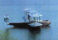
В 1918 году компания "Vickers" разработала легкую амфибию, крыло и оперение которой были выполнены по бипланной схеме. Фанерный корпус лодки был изготовлен по технологии Consuta фирмой С. Е. Саундерса. В нем находилась закрытая кабина для четырех пассажиров. Двигатель 275-сильный (205 кВт) Rolls-Royce Falcon был установлен на подкосах под нижним крылом и приводил в движение толкающий воздушный винт.
Получивший обозначение Viking, самолет совершил первый полет в конце 1919 года. А 18 декабря 1919 года при вынужденной посадке на нем погиб шеф-пилот компании - сэр Джон Алкок.
На базе лодки Viking I было спроектировано семейство машин, отличавшееся рядом доработок, в основном корпуса (некоторые с открытой кабиной), и различными типами силовых установок. В их число входили построенные в единственном экземпляре Viking II (360-сильный/268 кВт ПД Rolls-Royce Eagle VIII) и Viking III (450-сильный/336 кВт ПД Napier Lion), за которыми последовал серийный вариант Type 54 Viking IV. 26 самолетов были проданы ВС Аргентины, Канады, Франции, Японии и Нидерландов, а также для гражданского использования - в Аргентину, Канаду, СССР и США.
Последним вариантом стал Viking V с ПД Napier Lion; два таких самолета были построены для службы в составе британских ВВС в Ираке.
<...>
Показать полностьюShow all
История конструкций самолетов в СССР до 1938 г.
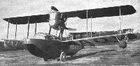
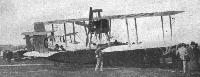
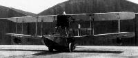
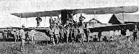
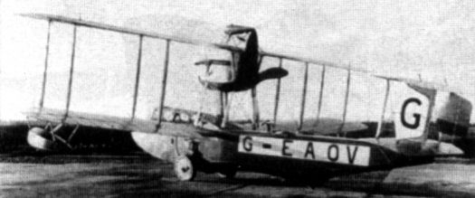
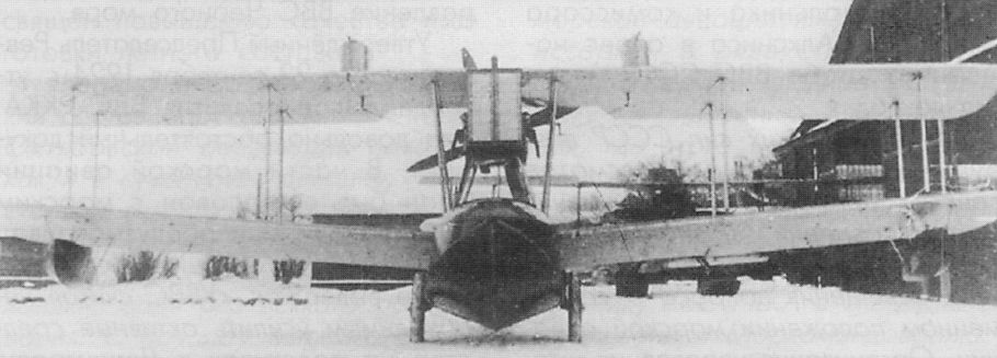
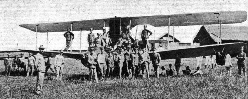
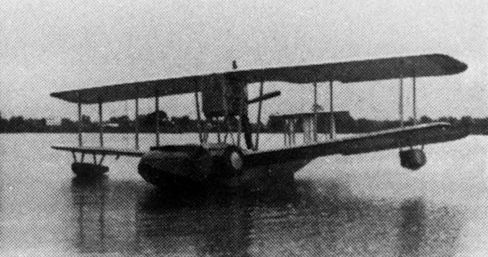
Амфибия "Виккерс-Викинг" , тип IV, - это летающая лодка, двухстоечный биплан с толкающей установкой двигателя "Нэпир-Лайон" в 450 л. с. Колеса поднимались вдоль бортов лодки вперед, костыль, он же водяной руль на заднем редане, не убирался. Летчик и летнаб находились в носовой части лодки, стрелок - за винтом. Конструкция деревянная. Был приобретен осенью 1922 г. в одном экземпляре. В 1923 г. летчик Л. И. Гикса с механиком Радеевым совершил на нем перелет из Петрограда в Севастополь.
Самолет "Виккерс-Викинг"
Год выпуска 1921
Двигатель , марка "Нэпир-Лайон"
мощность, л. с. 450
Длина самолета, м 10,22
Размах крыла, м 15,24
Площадь крыла, м2 63,5
Масса пустого, кг 1850
Масса топлива+ масла, кг 230+25
Масса полной нагрузки, кг 780
Полетная масса, кг 2630
Удельная нагрузка на крыло, кг/м2 41,5
Удельная нагрузка на мощность, кг/лс 5,8
Весовая отдача,% 29,7
Скорость максимальная у земли, км/ч 170
Потолок практический, м 4300
Продолжительность полета, ч. 4
Дальность полета, км 650
Показать полностьюShow all
Flight, June 1920
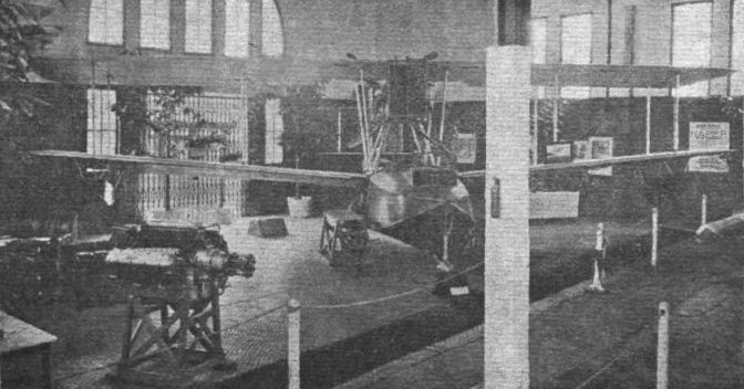
THE VICKERS VIKING
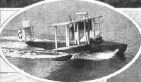
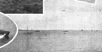
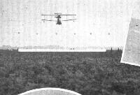
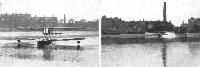
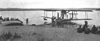
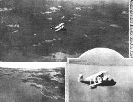
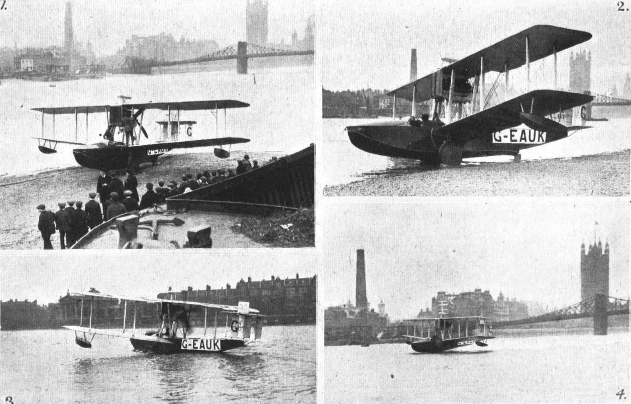
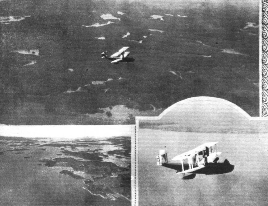
AN extremely interesting film was shown at Vickers House last week in which their very clever sea and land flying boat was convincingly seen. This craft which would, except for unforeseen circumstances, have been staged at the Paris Show, will be on view at Olympia. The neat way in which the craft came down the launching stage on her own wheels and took the water with the ease of a duck and within a moment or two had tucked away by her side her land impedimenta and rose gracefully from the sea, climbing well and quickly getting fine speed, was a revelation. Later she was seen emerging out of the distance, gradually descending to the sea again, and continuing to taxy towards the shore. As the edge of the sands was approached, one began to wonder when she was going to come to and turn in the water. But nearer and nearer she continued straight to the spectators on the sands, and it was then realised, as she glided gently out of the sea that she had again her land gear in operation enabling her to run up the sands without the slightest effort or assistance. Yes, a very convincing performance.
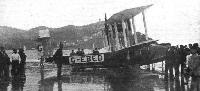
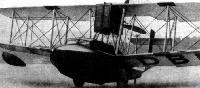
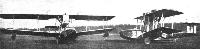
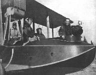
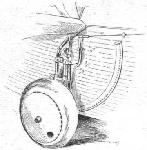
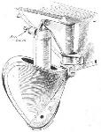
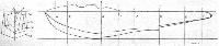
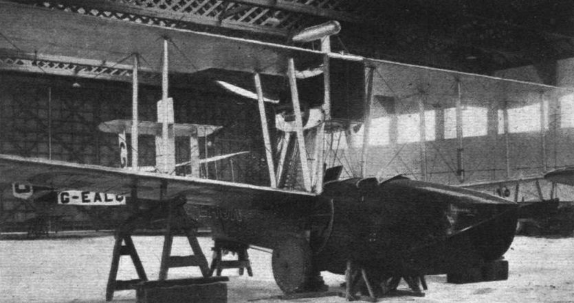
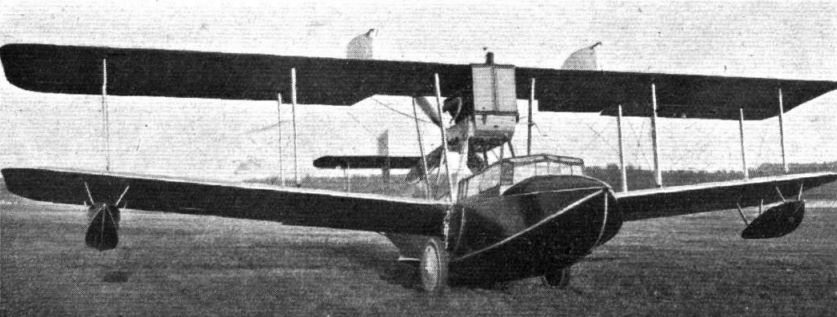
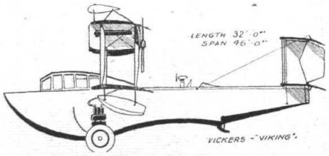
The Vickers "Viking" is a five-seater amphibious biplane of the flying-boat type, capable of starting from and alighting on either land or water. The hull is of the two-step type of rather unusual pattern, as may be seen from the accompanying illustration. The planing surfaces, from stem to stern, are of V-form, the curves of the keel and chine lines being convex as far as the first step, but between the latter and the second step - which is situated some distance aft - they are concave, and from the second step the V bottom slopes upwards and tapers to the vertical knife-edge stern of the hull. The top deck of the hull is perfectly flat and horizontal, whilst the sides are also flat and vertical, giving a simplicity of form that should make for ease of construction.
The pilot's and passengers' cockpits are enclosed by a roomy "glass-house" cabin, more or less streamlined. If required, three seats may be removed, giving 76 cubic ft. of space for freight or mails. The landing gear (terra firma) consists of two self-contained units, each comprising a wheel mounted on a shock-absorbing arm, which is pivoted at its upper end to the hull-side at a point some distance above the first step. When desired each wheel unit may be swung up alongside the hull by means of a crank mounted on the wheel arm, and operated through rods from the cabin. A tail skid is mounted on the keel at the second step.
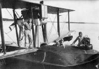
The engine, a 360 h.p. Rolls-Royce, Eagle VIII, is mounted in a streamline housing above the hull immediately below the top plane, and drives a 4-bladed pusher screw. The main planes are of equal span and chord, without stagger or sweepback, but with lower plane set at a comparatively large dihedral angle. A biplane tail is fitted having two balanced rudders, in between which is a vertical fin. Wing-tip floats are also fitted.
The general characteristics of the Vickers "Viking" are :-
Span 46 ft. 0 ins.
Chord 6 ft. 0 ins.
Gap 7 ft. 0 ins.
Overall length 32 ft. 0 ins.
Overall height 13 ft. 0 ins.
Weight fully laden 4,545 lbs.
Показать полностьюShow all
Flight, July 1920
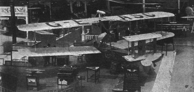
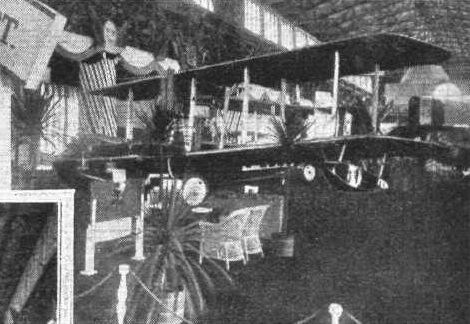
The Olympia Aero Show 1920
The machines
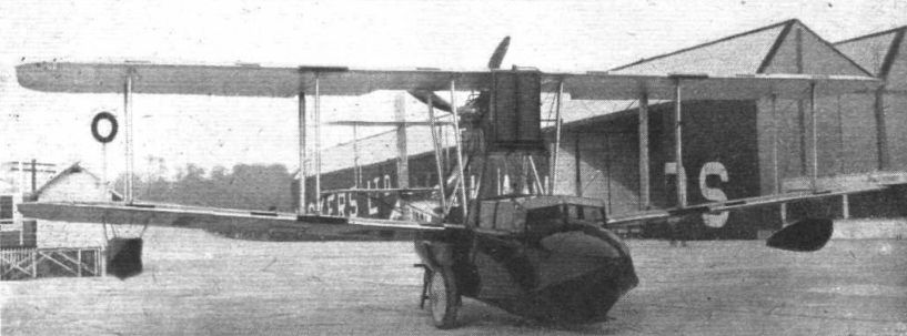
Vickers, Ltd. (STAND 50) Vickers House, Broadway, Westminster, London.
There is little doubt, that the "Viking" amphibious machine to be exhibited by Messrs. Vickers, Ltd., will cause considerable interest, not only on account of its combination landing gear, which allows it to alight on and start from either land or water, but also because, as a flying-boat, this machine represents a departure from standard practice, its hull design being considerably out of the ordinary. The flying-boat hull of the "Viking" has a pronounced Vee bottom both forward and aft of the step. Two retractable land wheels are mounted one on each side of the boat. These are operated from the pilot's cockpit, and can be raised and lowered during flight. If, therefore the machine is used, as it would be, chiefly over sea, but has to make land going journeys in the course of its duties, it is able, should necessity arise, of alighting safely on an ordinary aerodrome.
A "conservatory" roof is fitted over the top of the boat, inside which the three passengers and two pilots are comfortably housed. If it is desired to use the boat for cargo carrying, three of the seats can be removed, when a space of 76 cu. ft. is available for commercial load. The engine, a 360 h.p. Rolls-Royce "Eagle," Mark VIII, is mounted high in the gap between the planes, and drives a small diameter four-bladed air-screw (pusher). The "Viking" has an overall length of 32 ft. and a span of 46 ft. Fully loaded, in flying trim, the weight is 4,545 lbs.
Vickers, Ltd.
As the only amphibian machine at the Show, or at any rate shown as such, a great deal of interest naturally centres around the Vickers "Viking." That the aeroplane which is capable of alighting on either land or water at will will score over one fitted for one element only will be obvious. In the course of the duties of a commercial machine it will often happen that a land machine may have to cover a fair stretch of sea, or that a seaplane may have to travel considerable distances over land. If not of the amphibian type this will always entail a certain amount of risk, which is greatly reduced or even avoided by a combined land and water undercarriage. Unfortunately, carrying a set of wheels and their operating gear means a considerable extra load on the machine, which could be utilised for paying cargo. Unless therefore, the stretches of land over which the machine has to fly are very considerable, it is evident that the land chassis will not be carried. For many purposes for which aircraft will be used in the future conditions will, however, be such that if the machine is to perform its work it will have to be capable of alighting on either, and any attempt at producing a satisfactory combination is therefore to be greeted a step in the development of aircraft.
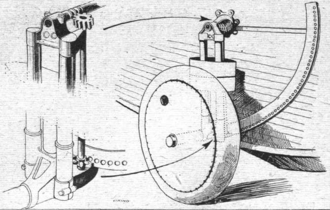
In the Vickers "Viking" the hull is flat-sided, and each side has an arc of sheet steel with a series of holes in it. A small star wheel is carried at the lower end of a shaft passing down along the tubes of the wheel undercarriage. This shaft is operated from the pilot's seat through a transverse shaft near the top rails of the boat, so that as the shafts are rotated they rotate the star wheel engaging with the arcs or quadrants on the sides of the hull, and thus lower or raise the wheels. Messrs. Vickers, Ltd., have had a most interesting film taken which shows the behaviour of the machine both on land and sea, and as far as could be seen both were highly satisfactory. It is quite amusing to see the machine come taxying in, and then without hesitation climb up on the beach. The machine certainly appears to get off well, and the unusual hull design, which has been the subject of some speculation, appeared to be quite effective, the machine getting off and alighting with no more spray than one associates with all flying boats. On land also the machine appears to behave very well indeed, although it is possible that after a great number of landings the hull might become strained. It will be realised that the hull has to be considerably stronger when used thus, owing to the whole weight of the machine coming at one point, instead of being more or less distributed over the hull as it is in the ordinary flying boat. If, however, the land undercarriage is used chiefly in emergency there would appear to be no reason to suppose that the gear would not be successful and capable of lasting quite a long period.
Показать полностьюShow all
Flight, September 1920
THE AIR MINISTRY SEAPLANE (AMPHIBIAN) COMPETITION
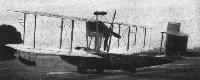
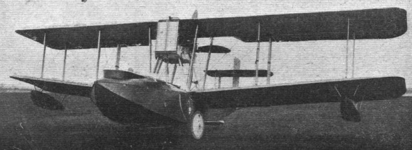
The Vickers "Viking" 450 h.p. Napier "Lion"
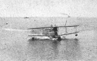
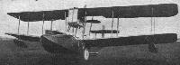
Apart from the fitting of a Napier "Lion" engine, the machine entered by Messrs Vickers, Ltd., is very similar to that exhibited at the recent Olympia Show. The boat hull is a Vee-bottomed, flat-sided structure of Consuta ply-wood attached to light internal stringers and formers. It is a question whether this form of hull is as strong, weight for weight, as one of circular or elliptical section. At any rate, modern tendency in flying-boat design appears to be towards the Linton Hope type, rather than the box form, but for a high-performance, lightly-loaded machine like the "Viking" the flat-sided hull is probably quite strong enough. The machine is not, one presumes, designed for use in a really rough sea, and for the more sheltered waters the hull appears to be eminently suitable. The get-off of the Vickers "Viking" is nothing short of extraordinary, both on land and sea, and in a smooth sea at any rate she appears to be very dry. The hull lines are somewhat unusual, the downward sweep of keel and chines in front of the rear step being rather more pronounced than usual, and this appears to be accompanied by an absence of any tendency to "porpoise."
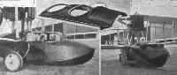
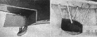
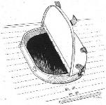
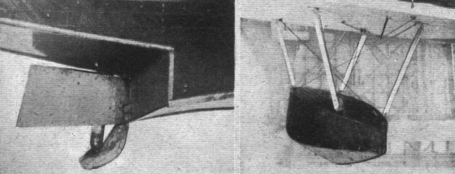
The passengers are accommodated in two cockpits in addition to that of the pilot. One of these is forward, while the second is placed aft of the main planes. The latter has a loose, hinged aluminium cover, which can be strapped on when the cockpit is not in use. This cover forms the subject of one of our sketches.
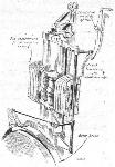
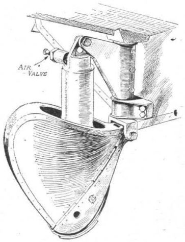
The combined tail skid and water rudder is placed immediately aft of the rear step, and one wonders whether it will not be found that in this position the water being deflected by the step will reduce the efficiency of the water rudder. It is possible, however, that at low speeds, when the water rudder is most needed, the water is not deflected sufficiently seriously to interfere with the action of the rudder, while at higher speeds the air rudder has already become operative. In principle the combined skid and rudder is similar to that of the Show machine, but the actual shape of the skid is slightly different.
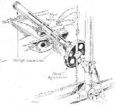
The land undercarriage is the same as that of the earlier model, consisting of two wheels mounted on telescopic tubes with Tee-pieces for the rubber shock absorbers. A star wheel at the lower end of the vertical rotating shaft engages with holes cut in the steel quadrant running up the side of the boat. The vertical shafts carry at their upper end a worm wheel engaging with the worm on the end of the transverse shaft passing through the boat hull. The wheels are thus lifted clear by being moved forward and upwards along the sides of body. The details of the gear are illustrated in the accompanying sketches.
A slight alteration is noticed in the biplane tail, which has had a small vertical fin added above the upper tail plane. Otherwise the tail remains the same as that of the Olympia machine. The 450 h.p. Napier "Lion" engine is mounted between the planes, with a radiator in front of it. It drives a four-bladed pusher airscrew. The performance of the Vickers "Viking" is excellent fitted with this engine, both speed and climb being far above the normal for flying-boats.
Показать полностьюShow all
Flight, October 1921
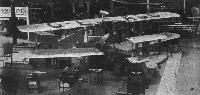
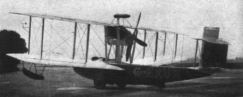
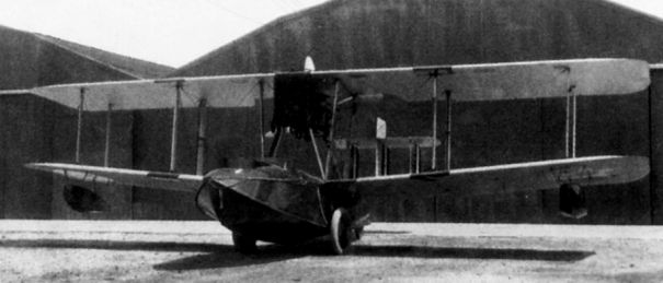
THE VICKERS "VIKING" MARK IV
Several Machines Building for Abroad
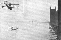
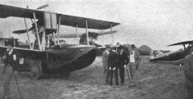
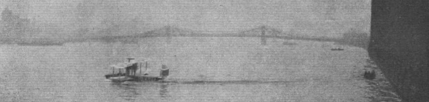
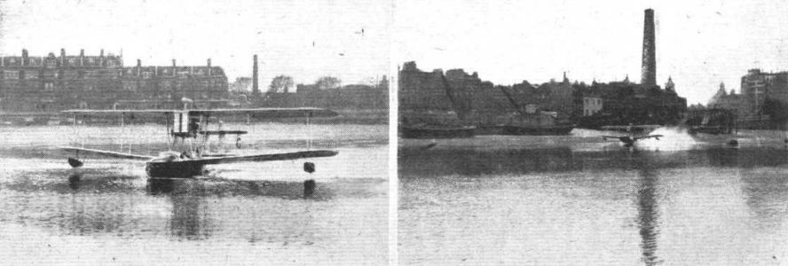
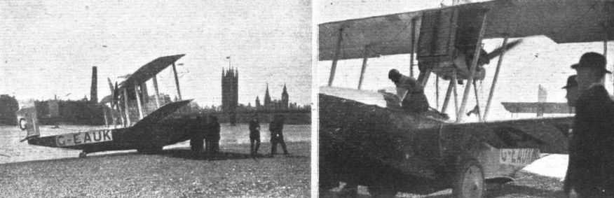
SINCE the Vickers Viking, Mark III, won the Government competition for amphibian machines at Martlesham, in September of last year, that machine has been doing a good deal of experimental work so as to obtain data for the next in the series, the Mark IV. Among the experiments and demonstrations which have been made with the older machine it will suffice to recall the trips between London and Paris - from Thames to Seine and vice versa - one of which was accomplished in the record time of two hours. No one who had the good fortune to witness the ease with which that machine got off from and alighted on the river could be in doubt about the enormous possibilities which the amphibian type of machine possesses. The majority of large towns have rivers running through or near them, which can be made to serve as "aerodromes," thus doing away with the expense of preparing land aerodromes, which must of necessity be some distance away from the centre of the town, and which, therefore, take up valuable time to reach.
The drawback to the amphibian type of machine is, of course, that the amphibian gear runs away with some of the load that could otherwise be utilised for paying cargo. It is yet too early in the development of the amphibian to make it possible to lay down any hard and fast rules as to what percentage of useful load will be absorbed by the land gear, and consequently it is impossible to strike a balance between the two types. On the one hand, there is the fact that no prepared aerodrome is required, and, therefore, no ground rent to pay nor ground maintenance. On the other, the amphibian will carry less useful load - by the amount equal to the weight of the land gear - than the land machine of the same power and performance. From the point of view of military (or naval) aviation, there can be little doubt that the amphibian will find its sphere of usefulness.
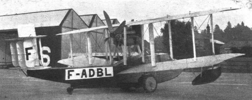
However, to return to the Vickers "Viking" amphibian, the experience gained with the Mark III "Viking" since its winning of the competition last year, has indicated that a more seaworthy hull would be desirable, and consequently Mr. Pierson, chief designer of Vickers' aviation department, set to work to improve upon the III. The result is shown in the Mark IV, several of which are now ready, and others nearing completion. It is not without interest to note that France has placed an order for new "Vikings," while a small country like Holland has also ordered several, some of which are about to be delivered immediately. The first machine, for France, is ready and will probably have been delivered by air by the time this week's issue of FLIGHT is distributed. It may be remembered that among the distinguished passengers carried between Paris and London on the Mark III was M. Laurent Eynac, French Under-Secretary of State for Air, who has evidently been so impressed by the qualities of the Mark III that he has sanctioned the ordering of the later model.
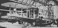
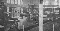
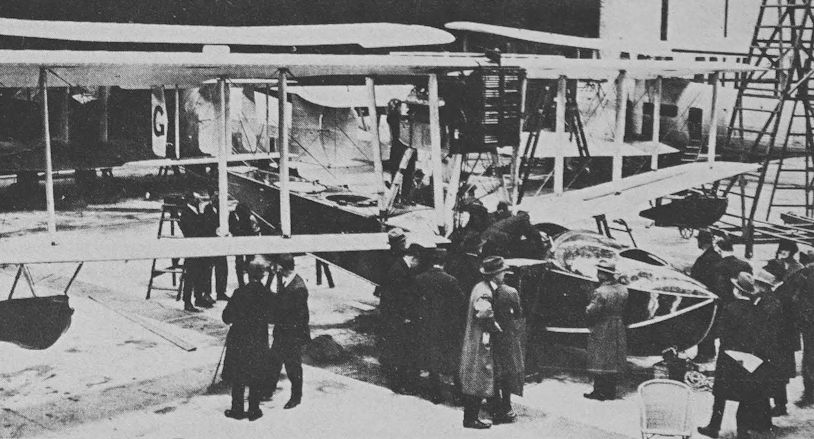
By the courtesy of Messrs. Vickers, Ltd., our representatives were permitted to inspect a number of "Viking IV's" at their Weybridge works the other day, where they had the privilege of seeing the machines being manufactured, and of having the details explained by Mr. Pierson and Mr. Muller, superintendent of the works. Except for minor changes in certain details, the Mark IV differs from the III chiefly in the beam of the hull, which has been increased by about one foot. The increase in cabin space which has resulted is astounding. The new hull is very roomy, and the behavior of the machine both in getting off and alighting is, we understand, greatly improved.
Except for the greater beam, the lines of the boat hull are but little altered. The same two steps in the vee bottom, spaced widely apart, are found in the new machine, and the tumble-home sides of the narrower hull have also been retained. The construction is the same as before, with a planking of mahogany built up on the "Consuta" principle, invented by Mr. Saunders of Cowes. The inner and outer skins have their strips at right angles to one another, and each makes an angle of approximately 45 degrees with the line of flight. The main frames are also of mahogany, while the intermediate timbers and longitudinal stringers, as well as keel, chines and gunwales, are of rock elm. In spite of the extra beam, the new hulls are very little heavier than the old one, due chiefly to the employment of thinner but more closely spaced stringers.
In the bottom of the hull the stringers are spaced approximately three inches apart, while the sides do not call for the same strength and consequently have their stringers spaced much wider. The planking is through-fastened to stringers and timbers and screwed to the frames. In consequence of the use of "Consuta" planking, the work of planking the boat hull is stated to be very considerably less than in the case of a boat-built hull, and the only places where it is possible for a leak to occur is where the planking joins keel and chines. These joints being well laid in red lead, with fabric strip coverings between them and the outer keel and chines, there is scarcely any possibility of an appreciable leak anywhere.
The steps are vee-bottomed also - that is to say, there is no flattening out from bows to front step nor from front to rear step. The main (front) step is open, i.e. water is a owed to enter into the angle formed by the step bottom and the main planking. In the case of the rear step a different arrangement has been employed. The face of this step is closed, and the whole interior of the step is water- and airtight except for small vent holes inside the hull to prevent bursting.
Just aft of the rear step is a small water rudder and tail skid combined. The shape and general design of this water rudder will be gathered from the accompanying sketch. The rudder is sprung by an oleo-pneumatic combination, and has been found, in spite of its position, immediately aft of the step, where one might expect it to be working in very disturbed water, to be very effective, not only in the water but also when performing the function of a steering tail skid.
The Amphibian Gear
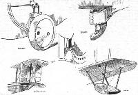
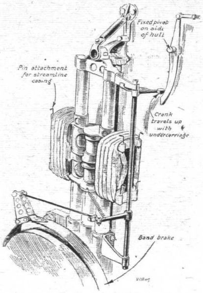
Except for minor improvements the amphibian gear remains almost identical with that of the older model. Certain parts have been strengthened up or simplified, but the general principle remains the same. The telescopic vertical tube carrying the wheel is pivoted at its upper end, which has a worm-wheel engaging with a worm on the end of a shaft running across the hull. This shaft is rotated by a wheel in front of the pilot via chains, and in rotating operates the vertical shaft which terminates at its lower end in a star wheel engaging with holes in the quadrant bolted to the sides of the hull. In rotating, the shaft swings the wheel forward and upward. As the arm of the wheel is long, and that of the operating shaft very short, the process of raising the wheel takes some little time. This, however, is of small importance, since there is scarcely any likelihood of the wheels having to be raised in a hurry. Lowering the wheels is a performance occupying a few seconds only, and in case of engine failure while flying over land it is therefore an easy matter to lower the wheels before a landing has to be made. The lower ends of the telescopic tubes are housed in a phosphor-bronze casting which has a substantial lip gripping another casting permanently fixed on the hull, and with which it engages only when the wheel is right down. The outward pull caused by the wheel at this point is transmitted across the hull by special strutting and wiring in way of step, so that there should be no possibility of it pulling off, even in a rough landing.
One very important addition has been made to the landing gear, i.e. the fitting of band brakes. The manner in which these have been designed to allow of the upward travel of the wheels is most ingenious. The operating gear consists of two separate units. One remains fixed on the hull and the other travels up with the wheel. One of our sketches shows the gear, and is, we think, self-explanatory. The curved portion of the vertical rocker on the side of the hull is, of course, shaped to the arc of a circle having the main pivot as its centre and the distance from this to the end of the lower-system lever as radius. The whole is extremely neat and light, and must be the outcome of many other alternatives. The effect of the band brakes is to enable the machine to be pulled up in about a third of the distance required without the use of brakes, so that their fitting has evidently been extremely worth while. In order to avoid one brake being applied harder than the other a compensating device of the usual form has been incorporated.
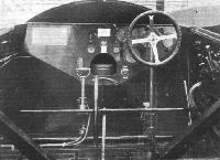
The Cockpit
One of our illustrations shows the controls and instrument board of the "Viking IV." Lateral control is by means of a wheel, and the longitudinal shaft, which runs aft until its end is in line with the rear spars, has a universal joint where it is secured to the vertical column. On the pilot's left are the wheel for raising and lowering the land gear, and the hand petrol pump. On the right he has the brake lever which operates the compensated band brakes on the wheels.
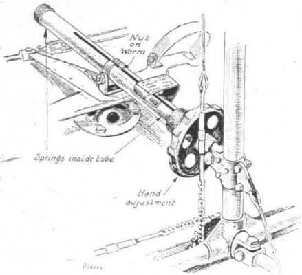
A very neat spring loaded setting is provided for the elevator. This is in the form of a worm housed in a tube mounted on the foot-bar pivot. A nut on this worm is prevented by a slot from turning. Two springs surround the worm, one on each side of the internal nut. A small duralumin wheel is mounted near the end of the worm, outside the tube. The rear end of the worm is attached to the control column. Rotation of the duralumin wheel causes the internal nut to travel along the worm, thus compressing one or other of the springs and thereby pushing the worm farther out of or into the tube, according to direction. By suitable setting the machine can be trimmed by means of the elevator instead of using a trimming tail plane. The external appearance is shown in sketch, which gives a good idea of the simplicity and neatness of the arrangement.
The seating arrangement consists of two pairs of side-by-side seats in front of the wings, and one seat aft of the wings, bringing the total up to five, including pilot.
The machine built for France is provided with two forms of of accommodation. One is a simple open cockpit covering of “Consuta,” while the other is a “coach-roof” cabin of Triplex glass, so arranged as to be interchangeable with the open cockpit type. The change-over takes about three-quarters of an hour. The various panels in the enclosed cabin roof are made to slide on small rollers, so that both side and front windows may, if desired, be kept open. According to Capt. Cockerell the enclosed cabin is quite nice to fly in, even from the pilot's point of view, while as regards the passengers it relieves them, of course, entirely from draught.
The main petrol tanks - two in number - are placed on strong floor frames in the bottom of the hull. A service tank is now incorporated in the top centre section, which adds greatly to the clean appearance of the machine.
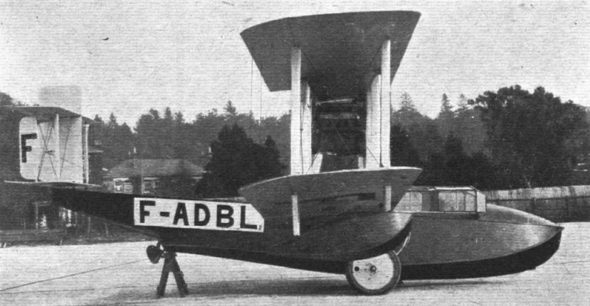
The Napier "Lion" low-compression engine is mounted high in the gap, on a framework of struts forming a letter W as seen from in front. It drives a four-bladed pusher air screw. The radiator is placed in front of the engine, and the lower portion of the latter is enclosed in a black japanned cowling which looks very smart.
As regards wings and tail planes there is little or no alteration. In the tail a certain amount of resistance has been saved by making the upper fin a cantilever. Otherwise the biplane tail remains as before. The wings are of larger area than those of the III, but are of the same general construction.
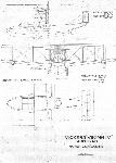
The machine which is being built for France has a span of 46 ft. and an area of 585 sq. ft. The wings are so hinged as to fold forward, the rear struts in way- of hinge being in two halves whose centres are held together by a clip, as it was found that they had a tendency to whip outward on account of the aerofoil section of each of the two halves.
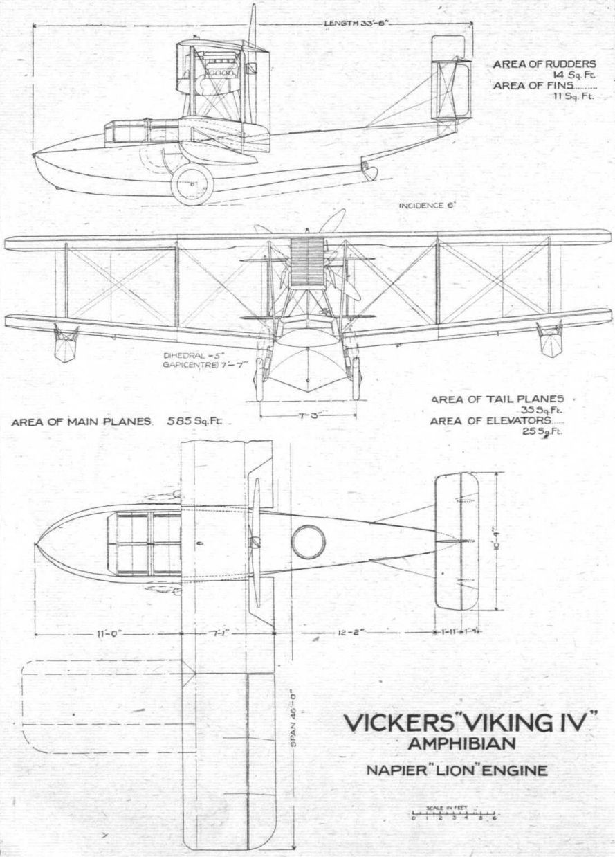
The machines built for Holland have open cockpits and a forward gun position. They are also provided with dual control. These machines have a slightly larger area, their span being 50 ft. Otherwise the two machines are identical. There is very little difference between the performance of the two machines, although we understand that the larger machine is, if anything, the nicer to fly. Our scale drawings show the smaller machine with folding wings, while the following particulars, apart from wing span and area, apply to both machines :-
Length overall, 33 ft. 6 ins. Span, 50 ft. Chord, 7 ft. 1 in. Gap at centre, 7 ft. 7 ins. Wing area, 636 sq. ft. Incidence, 6°. Dihedral: Top plane, nil; bottom plane, 5°. Weight empty, 3,740 lbs. Petrol, 80 gals, (tankage, 115 gals.). Oil, 6 gals. Pilot, 180 lbs. Available for passengers and/or freight, 1,133 lbs. Total loaded weight, 5,675 lbs. Loading per sq. ft., 8-9 lbs. The machines can be fitted either with high-compression or low-compression "Lions." The respective performances are as follows: High-compression - speed near sea level, 118 m.p.h.; climb to 3,000 ft., 3 mins. 16 secs.; time to get off, 10 secs. For the low-compression engine the figures are 114 m.p.h., 14 mins 19 secs., and 14 secs, respectively.
Показать полностьюShow all
Flight, July 1923
Gothenburg International Aero Exhibition 1923
THE MACHINES
Vickers, Ltd., Vickers House, Broadway, London, S.W.1
THE well-known firm of Vickers are, in addition to various aircraft component parts referred to hereafter, showing the "Viking" Mark IV, a pusher biplane amphibian flying-boat, fitted with a 450 h.p. Napier "Lion," and intended for general service.
The building of the "Viking" was first discussed in December, 1918, and "Viking" Mark I was flying in February, 1919. The experience gained with this type was incorporated in "Viking" Mark II, which was launched at the end of that year.
After many improvements had been added to this machine, she was entered for the Antwerp Exhibition in July, 1920, and was classified as first in the following :- (a) Shortest time in getting off the water; (b) fastest time over a given circuit; (c) shortest time in climbing to 1,000 metres; (d) highest ''ceiling" or altitude with full load.
This competition was an international one, open to all types of seaplanes and flying boats, so that the success of the "Viking" was particularly creditable, and a noteworthy triumph of the amphibian over other types.
The development of this type of aircraft was considered so vital by the British Air Ministry that early in 1920 a prize of ^10,000 was offered by them for the most efficient type of amphibian produced in the British Isles.
In this competition, which took place in September, 1920, the first prize of ^10,000.was won by the "Viking" Mark III, and it was won under such exacting conditions that only an exceptionally well designed and constructed machine could have withstood the tests.
The advantages of the amphibian type of machine are obvious, as it can arise from or alight on either land or water at will, whereas it is undesirable for an ordinary seaplane to fly large distances over land, or for a land machine to fly over large tracts of water.
The "Viking," owing to its exceptional performance and manoeuvrability, can get off from or alight on a seaplane carrier. Furthermore, after rising from the deck, it can, of course, alight with safety on the water - a decided advantage over the ordinary land type ship's 'plane. The ordinary flying boat is at a disadvantage for use on seaplane carriers, seeing that it cannot alight on the ship's deck nor arise from it.
In the "Viking" the wings are made to fold by a novel method, thus economising space. The wings fold forward, so that in flying the strain tends to keep them in position. When folded the "Viking" Mark IV occupies a space of 32 ft. by 35 ft.
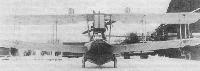
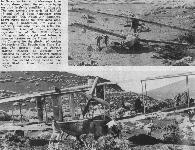
It is proposed to fit skis instead of wheels to this machine, so that a landing on or a rising from snow can be effected, and for use in countries that are snow-bound during certain periods of the year, it is proposed to fit skis in addition to wheels.
With the ordinary flying boat ar seaplane, it has to be provided with a trolley in order that it may enter the water from its hangar, or vice versa. The "Viking" carries its trolley with it in the shape of the retractable undercarriage, and by a simple operation the pilot lets down the wheels on approaching the slipway from the sea. Under its own power and without the assistance of a single attendant it runs up the slipway and into the hangar or from the hangar down the slipway into the sea.
As regards the general and constructional features of the "Viking." It has seating accommodation for six (including pilot) in open cockpits. The hull has many distinctive features, both in the design and in the construction, but, unfortunately, we have not the space now to more than draw attention to their presence. Mahogany and elm are mainly used in the construction of the hull. The main planes and tail planes are of spruce construction for ribs and spars, and mild steel tube for internal and interplane struts; bracing is by swaged and streamline wire. Control surfaces are built up of mild steel tube with spruce ribs. The main petrol tanks are carried within the hull, and a gravity tank in the upper plane is supplied therefrom by means of a Vickers wind-driven pump. The controls are of the standard wheel type.
The guaranteed performance, under standard conditions, of the "Viking IV" is as follows :- Full speed near sea level, 113 m.p.h.; minimum speed, 48 m.p.h.; climb to 5,000 ft., 8 1/2 mins.
The general dimensions are as follows :- Span, 50 ft.; chord, 7 ft. 1 in.; overall length, 34 ft. 2 ins.; height, 14 ft.; gap, 7 ft. 7 ins.; area of main planes, 635 sq. ft.; weight of machine empty, 4,030 lbs.; weight fully laden, 5,790 lbs.; loading per sq. ft., 9-12 lbs.; loading per h.p., 11-9 lbs.
Показать полностьюShow all


 Wiki
Wiki