


Flight, August 1938
SITTING on the SLIPSTREAM
Effective Lift Coefficient of Five Obtained With the Crouch-Bolas Engine Arrangement
AMAZING progress has been made with high-lift devices of different sorts during the last few years. Slots, slotted flaps, split flaps, rider planes and so forth raised the maximum lift coefficient from the 0.6 or so (in the old-fashioned British "absolute" units) of the thin, moderately cambered biplane sections in common use before the revival of the monoplane fashion to 1.5 or more when applied to the modern cantilever wing.
Obviously the increased unit lift can be used either to reduce landing speed for a given wing loading or for keeping the landing speed the same and increasing the wing loading, thereby obtaining an improvement in maximum and cruising speeds. The tendency has, rather naturally, been towards the latter course. Not only so, but the ability to steepen the gliding path by the use of flaps has made it possible to employ even greater landing speeds and trust to the new technique and greater skill of the pilot to make landings safe at the greater speeds.
Research is still being carried out in all manufacturing countries on devices for increasing unit lift still further, and some improvement may be possible. When it is made available, however, it will probably be utilised for still higher performance by a further increase in wing loading.
Two Englishmen have been working along quietly on a different line of attack for several years, their preliminary work, as it happens, having been carried out in America, although one of them has now returned to this country. Mr. R. J. Goodman-Crouch and Mr. Harold Bolas "emigrated" to America several years ago and there established a small company for experimenting with a scheme for obtaining increased lift by making use of the slipstream from the airscrews. It had, of course, been known long before that that the portion of a wing situated in the slipstream gives greater lift by virtue of the greater relative velocity of the air. But no one, apparently, had realised that by judicious "wangling" the degree of extra lift might be made to amount to a good deal. Messrs. Bolas and Crouch did suspect this fact and set to work on finding out exactly how much there is in it.
Surprising Results
Their results, from wind tunnel tests and from actual living tests carried out with a somewhat quaint experimental biplane, indicated that rather surprising “lifts” can be obtained. For the full slipstream effect to be obtained it is, of course, necessary that the airscrews should “cover” the entire wing. If they cover half the wing area, very roughly half the effect is obtained, and so forth. Fortunately for the two inventors the modern tendency in military as in civil aircraft is towards twin-engined and multi-engined machines, and it has been found that to obtain a fairly large percentage of the theoretically possible advantages it is not necessary to go to extremes in the matter of airscrew diameters.
Perhaps it will be recollected that a couple of years ago or so the annual report of the Aeronautical Research Committee referred to the desirability of research into the mutual effects of a large number of airscrews on the leading edge of a wing. The idea was, we believe, connected with large flying boats of 200 tons gross weight in which, with existing power plants, the total horse-power would of necessity have to be provided by a multiplicity of engine units. We are not aware it that research was carried out, or if it still remains a pious hope. Be that as it may, Crouch and Bolas have found that In covering the greater part of a wing with slipstream, and by tilting the airscrew axis downwards, a very great increase in lift is obtainable at low forward speeds. Moreover, the angle of airscrew tilt needed to give somewhere near optimum results is not great enough materially to affect the airscrew efficiency at cruising speed. At low forward speeds there is, of course, a considerable degree of slip, so that when the aircraft as a whole is travelling slowly the speed of the slipstream across the wing is high, and the wing obtains the high tilt which results from high relative air velocity at large angles of incidence.
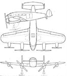
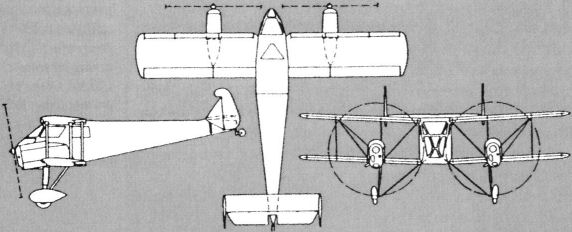
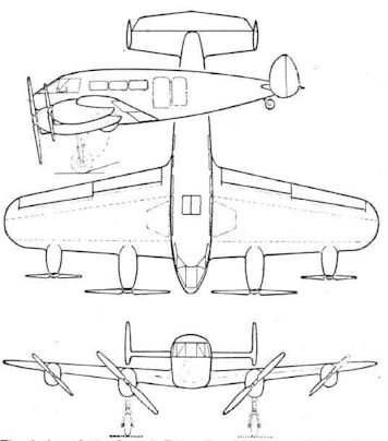
That an aeroplane incorporating the Crouch-Bolas ideas need not be unsightly, nor even very unorthodox in appearance, is indicated by the three-view general arrangement drawings of the C. B. Speed-Ranger, a design which was evolved some time ago.
In this the inboard engines develop 420 h.p. each, while the outboard engines produce 145 h.p. each. The speed range is estimated to be from 245 m.p.h. to 34 m.p.h., or slightly over 7 to 1.
The tapering of the power units has certain advantages, apart from its use in the increase of lift. The distributed load along the wing spars reduces the bending moments, while the fact that the lower-powered engines are outside reduces the yawing moment on the machine in the unlikely event of a stoppage of an outboard engine. Incidentally, the machine is designed to fly on one inboard engine alone.
Mention has already been made of the fact that one ot the essential features of the Crouch-Bolas scheme is that the airscrew shaft should make a negative angle with the wing chord. On the experimental biplane provision was made for varying this angle in order to determine the optimum arrangement. It was found that the angle need not be very large and that in practice there is no need for such elaborations as tilting engine mountings. The wing itself is slightly more efficient when placed in an airstream tilted upwards a little, the effect being rather similar to that found in a glider soaring in an up-current. This gain in wing efficiency is just about sufficient to offset the very small loss in airscrew efficiency at cruising speed which results from tilting the airscrew axis.
As the increase in lift results from accelerating the air which passes across the wing, it follows fundamentally that it can be superimposed upon and added to the extra lift obtained from such devices as slots and flaps. Calculations based upon research and experiments indicate that an aircraft with the usual modern high-lift devices and tilted airscrews whose swept area covers the greater part of the wing can be expected to give a maximum lift coefficient of 5.0 (or 2.5 in the old "absolute" units). This may seem staggering, until one remembers that in calculating ”backwards,” so to speak, one takes into account wing loading and forward speed of aircraft (which is low), but not slipstream speed across the wing. In actual figures it means, using the old fundamental formula, L = W= Cl p A V2, that lor a wing loading of 50 Ib./sq. ft. the minimum speed would be about 63 m.p.h.!
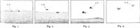
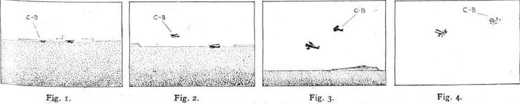
That all this is not mere theorising seems to emerge from the flying tests carried out in America with the experimental biplane some time ago. Climbing and gliding angle rather than landing speed were the objects aimed at, and we have pictures from a film taken at the time which shows the takeoff and landing of two machines, one the Crouch-Bolas experimental biplane and the other a normal standard American biplane. Both machines had a wing loading of 10.5 Ib./sq. ft., and the conventional biplane had considerably more power than the C.-B. Unfortunately, the film pictures are too small and too indistinct for reproduction, but we have had prepared from them the small sketches, which represent quite accurately what the film shows.
Fig. 1 shows the machines taking off together. Four seconds later the Crouch-Bolas machine had left the ground, and Fig. 2 shows it already in the air while the conventionally designed machine is still on the ground.
At a safe height, i.e., when it is permissible to place the machine in what normally would be a stalled attitude, the nose is elevated and the machine is climbed at low forward speed but at the same rate of climb, thus increasing the angle of climb far beyond the normal.
Fig. 3 shows the two aeroplanes in their respective positions at this point, while Fig. 4 gives an indication of the distance travelled by both aeroplanes in order to reach the test height.
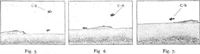
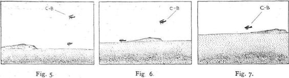
In the case of landing the increased angle of descent and the low forward speed and decreased sinking velocity are clearly demonstrated.
Fig. 5 shows the Crouch-Bolas type descending at a steep angle, low forward speed, and low sinking velocity, with the conventional machine still behind it and below it lessening the distance between the two aeroplanes.
Fig. 6 shows the Crouch-Bolas type gliding in with its engines revving at slow speed, so that in the remote event of engine failure the far that the aeroplane is flying at less than its stalling angle without engines constitutes no increased hazard whatsoever on this score.
The conventional machine, however, with its normal landing speed has been forced to overtake the Crouch-Bolas machine and is seen in the photograph well in, advance of its competitor and already on the ground, commencing its landing run
Fig. 7 shows the Crouch-Bolas in the process of dropping its tail preparatory to making a low-speed landing, this manoeuvre normally being carried out either when in close proximity to the ground or at the time of contact, in order to avoid any possible danger which might arise from the unlikely failure of an engine.
The subsequent landing occupies but a short space, ten to fifteen yards being the average sort of figure.
The position of the Crouch-Bolas when landing is shown in Fig. 8; its attitude can be judged from the position ol the tail wheel.
As a result of tests and calculations it is claimed foi the Crouch-Bolas scheme that it will:
1. Decrease the time and distance for take-off by 50 per cent.
2. Increase angle of climb while retaining the same rate of climb, by nearly 100 per cent.
3. Increase the speed range by approximately 75 per cent.
4. Decrease the sinking speed, as distinct from forward speed, to approximately 50 per cent, of that obtained on modern aircraft fitted with wing flaps.
5. Decrease the landing speed and distance run by about 50 per cent.
These characteristics, it is claimed, are achieved without sacrifice of maximum speed, load-carrying capacity or safety characteristics. Control and manoeuvrability are retained down to and beyond the stalling speed.
Capt. Goodman-Crouch, who has been back from America for some time, is now in touch with several British aircraft firms, and it may be expected that the Crouch-Bolas scheme will be applied to British machines in the not too-distant future. In the meantime Mr. Harold Bolas is watching the American end of the partnership, and there may soon be developments to report from the other side.
- Flight, August 1938
SITTING on the SLIPSTREAM
Фотографии

-

Air Enthusiast 2003-01 / K.Wixey - The Bolas touch
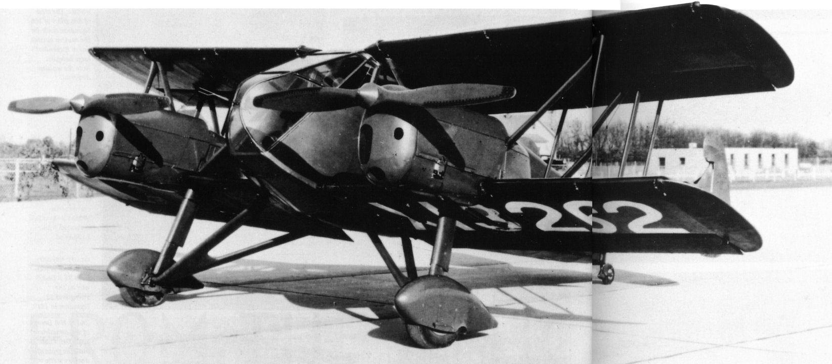
Регистрационный номер: X13262 [4] Crouch-Bolas Dragonfly of 1934 in its original form powered by a pair of Bolas-designed Dragon IV-Gs. Note the four-bladed cooling fans in the lower engine cowlings and the original-style nose section.
-

Air Enthusiast 2003-01 / K.Wixey - The Bolas touch
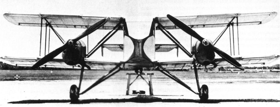
Регистрационный номер: X13262 [4] Head-on view of the Dragonfly re-engined with two Menasco B4s driving large diameter propellers. The aircraft's tail is raised on a trestle.
-

Air Enthusiast 2003-01 / K.Wixey - The Bolas touch
Регистрационный номер: X13262 [4] The Crouch-Bolas Dragonfly after receiving a new paint scheme, redesigned nose section providing an enhanced forward view, and a tailwheel in place of the original skid.
-

Flight 1938-08 / Flight
Регистрационный номер: X13262 [4] Fig 8. The Crouch-Bolas biplane in a typical landing attitude.
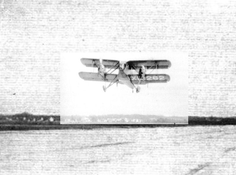
In its final configuration Dragonfly X13262 taking off from Colonel Green's private flying field at Round Hill, Massachusets, circa 1934. -
Flight 1938-08 / Flight
Stages in the take-off of the Crouch-Bolas biplane and an orthodox machine. Sketches prepared from a film.
-
Flight 1938-08 / Flight
Landing approach oi the Crouch-Bolas biplane and a conventional biplane. The sketches are accurate copies of an actual film.
-

Air Enthusiast 2003-01 / K.Wixey - The Bolas touch
In this three-view drawing of the Crouch-Bolas Dragonfly, the downward tilt of the engines is apparent. Over 70% of the total wing area was covered by propeller slipstream.
-
Flight 1938-08 / Flight
The design of the Crouch-Bolas Speed-Ranger indicates that little departure from conventionality need be incurred to obtain the full effect of the tilted slipstream arrangement.
-

Air Enthusiast 2003-01 / K.Wixey - The Bolas touch
Three-view drawing of the projected Bolas B-37 Speed Ranger passenger transport.
-

Air Enthusiast 2003-01 / K.Wixey - The Bolas touch
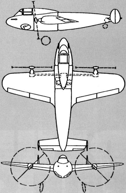
Three-view of the Crouch-Bolas B-40 Pursuit monoplane project.

- Фотографии