Wellington / Type 271
Средний бомбардировщик, цельнометаллический двухмоторный моноплан с убирающимся шасси с хвостовым колесом. Основное отличие конструкции - геодетический набор, обтянутый полотном. Экипаж 5 - 6 человек. Спроектирован в КБ фирмы "Виккерс авиэйшн" под руководством ДальшеMore>>>
Б.Уоллиса и К.Пирсона. Опытный бомбардировщик "тип 271" ("Креси") впервые поднялся в небо 15 июня 1936 г. Серийное производство начато в декабре 1937 г. под названием "Веллингтон". Строился на заводах "Виккерс" в Вейбридже, Честере, Блэкпуле, Смитс-Лауне. Всего выпущено 11 461 экз. (самый массовый английский бомбардировщик). Состоял на вооружении в Великобритании с октября 1938 г., во Франции - с середины 1945 г. (как учебный). Выпускался в вариантах бомбардировщика, противолодочного патрульного и военно-транспортного самолета, тральщика магнитных мин.
Основные серийные модификации как бомбардировщика:
- "Веллингтон" I с моторами "Пегасус" XX или XVIII, вооружение 4x7,69, на варианте IA - 6x7,69, измененный бомбоотсек, усиленное шасси; IC - перемещено вооружение, изменено внутреннее оборудование;
- "Веллингтон" II с моторами "Мерлин" X, вооружение по типу IC;
- "Веллингтон" III с моторами "Геркулес" XI, вооружение 8x7,69;
- "Веллингтон" IV с моторами R-1830S3C4-G, вооружение 8x7,69;
- "Веллингтон" X, вариант модификации III с усиленным планером и моторами "Геркулес" VI или XVI.
Бомбовая нагрузка до 1815 кг.
"Веллингтоны" применялись с сентября 1939г. как дальние разведчики, дневные и ночные бомбардировщики; с начала 1940г. - только ночью. В 1942 - 1943 гг. - основной самолет Бомбардировочного командования Королевских ВВС. С сентября 1940 г. "Веллингтон" начал воевать в Северной Африке, весной 1941 г. участвовал в отражении нападения немцев на Грецию, с апреля 1942 г. использовался на Дальнем Востоке (на индобирманском фронте). Применялся британскими ВВС до конца войны.
Снят с производства в октябре 1945 г. Снят с вооружения во Франции в 1947 г., в Великобритании - в марте 1953 г.
"Веллингтон" B.III||
Размах:||26,2 м
Длина:||18,53 м
Моторы, количество х мощность:||2x1375 л.с.
Взлетная масса, максимальная:||13400 кг
Максимальная скорость:||408 км/ч
Практический потолок:||5800 м
Дальность:||3500 км
Vickers Type 271 Wellington
Первый опыт с геодезической конструкцией самолета, полученный компанией «Vickers» при работе с Wellesley, позволил ей успешно принять участие в тендере на средний дневной бомбардировщик, требования к которому были изложены в спецификации B.9/32. «Vickers» получила контракт на постройку прототипа - моноплана со среднерасположенным крылом и убирающимся трехопорным шасси с хвостовым колесом, оснащенного двумя звездообразными моторами Bristol Pegasus X мощностью по 915 л. с. (682 кВт). Прототип был облетан 15 июня 1936 года, а 15 августа 1936 года компания получила первый заказ на 180 серийных Wellington Mk I. В октябре 1938 года самолеты стали поступать в IX эскадрилью, а к началу Второй мировой войны в сентябре следующего года в строю находилось уже восемь полностью оснащенных эскадрилий, тогда как другие продолжали принимать новые машины.
Всего до октября 1945 года был построен 11461 самолет всех модификаций. Данные бомбардировщики, прозванные «Wimpey» (J. Wellington Wimpey - герой американского мультсериала «Рореуе»), стали основой бомбардировочной авиации британских ВВС в Европе в первой половине войны и сыграли важную роль в битве за Атлантику. И после войны они оставались на службе - в начале 1950-х годов использовались в качестве учебных. Именно Wellington нанесли первые удары по Германии, но из-за тяжелых потерь в дневное время, начиная с 18 декабря 1939 года, их стали применять только ночью. Они также составили основу армады самолетов в известном рейде 1000 бомбардировщиков, а также использовались для уничтожения вражеских магнитных мин, постановки мин в водах противника и для испытания разнообразных силовых установок и вооружения.
Варианты: опытные и серийные
Type 271: первый прототип, облетанный 15 июня 1936 года
Type 285 Wellington МКI: предсерийный самолет с двигателями Pegasus X, облетанный 23 декабря 1937 года
Type 290 Wellington Mk I: начальный серийный вариант (183 самолета) с двигателями Pegasus XVIII мощностью по 1000 л.с.,турельными установками Vickers и турелью внизу носовой части фюзеляжа
Type 408 Wellington Mk IA: серийный вариант (187) с двигателями Pegasus XVIII, турельными установками Nash &Thompson и турелью внизу носовой части фюзеляжа
Type 416 Wellington Mk 1C: серийный вариант (2685); Type 423 включал в себя все бомбардировщики, переделанные для навески 1814-кг бомб; бортовые пулеметы сохранились, а подфюзеляжную турель удалили
Type 298 Wellington Mk II: опытный самолет с двигателями Merlin X мощностью по 1145 л.с., облетанный 3 марта 1939 года
Type 406 Wellington B.Mk II: серийный вариант с двигателями Merlin X; 400 самолетов
Type 299 Wellington Mk III: два опытных самолета с двигателями Hercules НЕ1 .SM и с двигателями Геркулес III
Type 417 Wellington B.Mk III: серийный вариант (1517) с двигателями Hercules XI мощностью 1500 л.с.
Type 410 Wellington Mk IV: опытный образец со звездообразными двигателями Pratt & Whitney Twin Wasp
Type 424 Wellington B.Mk IV: серийный вариант (220) с двигателями Twin Wasp
<...>
Type 440 Wellington B.Mk X: серийный вариант (3803) с двигателями Hercules VI или XVI; Type 619 - самолеты, переоборудованные после войны в вариант Wellington T.Mk 10; часть продана Франции и еще шесть - греческим ВВС в 1946 году
<...>
Варианты: экспериментальные
Type 416 Wellington (II): вариант прототипа Wellington Mk II с 40-мм пушкой Vickers в верхней части фюзеляжа и двухкилевым оперением
Type 418 Wellington DWI.Mk I: один самолет с оборудованием для подрыва мин и вспомогательной силовой установкой Ford
Type 419 Wellington DWI.Mk II: один самолет для подрыва мин; вспомогательная силовая установка Gipsy Six
<...>
Type 435 Wellington Mk 1C: один самолет для оценочных испытаний установки Turbinlite
Type 439 Wellington Mk II: экспериментальная установка 40-мм пушки Vickers в носовой части фюзеляжа самолета Wellington Mk II
<...>
Type 445 Wellington (II): летная лаборатория для испытаний турбореактивного двигателя Whittle W2B/23 в хвостовой части;
Type 470 и Type 486 - варианты Wellington Mk II с двигателями Whittle W2B и W2/700, соответственно
Type 478 Wellington Mk X: один опытный самолет с двигателем Hercules 100
Type 602 Wellington Mk X: летная лаборатория для испытаний турбовинтовых двигателей Rolls-Royce Dart
Wellington Mk III: один самолет для буксировки планеров Hadrian, Hotspur и Horsa
ТАКТИКО-ТЕХНИЧЕСКИЕ ХАРАКТЕРИСТИКИ
Vickers Wellington B.Mk III
Тип: средний бомбардировщик с экипажем из шести человек
Силовая установка: два звездообразных ПД Bristol Hercules XI мощностью по 1500 л. с. (1119 кВт)
Летные характеристики: максимальная скорость на высоте 3810 м - 410 км/ч; практический потолок 5790 м; дальность полета с бомбовой нагрузкой 2041 кг - 2478 км
Масса: пустого 8417 кг; максимальная взлетная 13381 кг
Размеры: размах крыла 26,26 м; длина 18,54 м; высота 5,31 м; площадь крыла 78,04 м2
Вооружение: восемь 7,7-мм пулеметов (два в носовой и четыре в хвостовой установке, а также по одному бортовому пулемету), плюс максимум до 2041 кг бомб или одна 1814-кг бомба
Flight, July 1939
GEODETICS on the GRAND SCALE
A Detailed Description op the Vickers-Armstrongs Wellington I : Exceptional Range and Large Bomb Capacity : Ingenious Structural Features
IT is extremely unlikely that any foreign air force possesses bombers with as long a range as that attainable by the Vickers-Armstrongs Wellington I (Type 290), which forms the equipment of a number of squadrons of the Royal Air Force and of which it is now permissible to disclose structural details.
The Wellington’s capacity for carrying heavy loads over great distances may be directly attributed to the Vickers geodetic system of construction, which proved its worth in the single-engined Wellesley used’ as standard equipment in a number of overseas squadrons of the R.A.F. But the qualities of the Wellington are not limited to load-carrying. It has a top speed of 265 m.p.h. (or considerably more when fitted with Rolls-Royce Merlin or Bristol Hercules engines in place of the Pegasus XVIIIs); it has provision for five turreted machine-guns; it is quite exceptionally roomy, and it is amazingly agile in the air.
The Bristol Pegasus XVIII engines fitted as standard in the Mark I Wellington is a two-speed supercharged unit with the following ratings; Take-off power, 965 h.p. at 2,475 r.p.m.; international power (using medium supercharge), 780/815 h.p. at 2,250 r.p.m. at 4,750ft.; international power (using full supercharge), 720/ 750 h.p. at 2,250 r.p.m. at 14,750ft.; maximum power (medium supercharge), 1,000 h.p. at 2,600 r.p.m. at 3,000ft.; maximum power (full supercharge). 885 h.p. at 2,600 r.p.m. at 15,500ft.
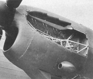
The Wellington’s engines drive De Havilland three-bladed constant-speed airscrews with a diameter of 12ft. 6in. They are carried on mountings bolted to the fireproof bulkhead frames, the installation being designed to allow quick replacement of a power unit. In addition to the usual Bristol long-chord gilled cowling with trailing-edge cooling gills, the engines are provided with louvred “dish pan” cowlings over the crankcases.
The exhaust on the port engine heats a boiler, the steam from which passes through a heater in the wing root; air warmed in the heater flows into a fore-and-aft duct running practically the whole length of the fuselage.
Each engine has its own fuel system, handling 500 gallons made up as follows: One main tank in engine nacelles (60 gal.); three wing tanks in front of spar in outer wing panel (138 gal.); three wing tanks behind outer spar (162 gal.), and one "overload" tank in the bomb compartment. The tanks are made of Alclad, the overload tanks being cylindrical in shape and secured in the bomb bays by straps. All fuel is available to either engine if required.
When the Wellington is making short- or medium-range flights the engines draw oil from tanks in the nacelles, but for long-range work an additional tank with a pump is fitted on the starboard side of the cabin. Apart from a thermostatically controlled Serck oil cooler and a Tecalemit oil cleaner for the main oil system, there is an additional Tecalemit cleaner for the two-speed blower system.
The “hydraulics” are of interest in that there are two separate systems. Of these the primary circuit supplies the undercarriage and tail wheel, the flaps, and the mechanism for operating the bomb doors, while the other system actuates the rotating, elevating, and depressing of the guns in their turrets.
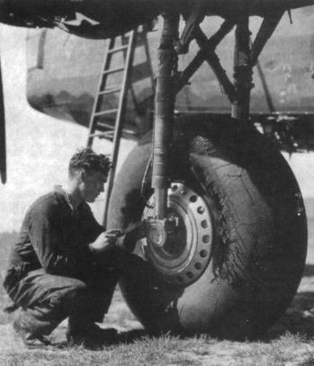
The undercarriage comprises the two main wheels and the tail wheel, all of which retract simultaneously under hydraulic power, their positions being signalled by visual and audible means. Each unit of the main gear embodies a double-acting hydraulic jack in conjunction with a twin-leg transversely braced assembly with a folding backstay. All three wheels are completely enclosed during flight.
As at present in service the Wellington has Vickers power-driven gun turrets in the nose and stern, the forward turret housing one machine gun. and the rear turret two of these weapons. Provision is made in the bottom of the fuselage for the installation of a power-driven retractable turret housing another two.
The Wellington I normally carries a crew of four, made up of a pilot, a front gunner (who is also the bomb aimer or navigator), a wireless operator (who acts alternatively as the midships gunner), and a rear gunner. Provision is made to carry a fifth man.
The cabin - which, due to the geodetic construction, provides a large amount of unobstructed space - is exceptionally well lighted for a military machine, thanks to the deletion of fabric over a number of the geodetic panels. From the cabin proper a catwalk extends through the fuselage to the tail gun turret. In the nose, just behind the turret, is a prone position for the bomb aimer. This section of the fuselage is provided with a large trap door for emergency exit; it is spring-loaded and operated by a pedal. Additional emergency exits are provided farther aft in the fuselage, and the occupants of the nose and tail turrets are provided with firemen’s axes to enable them to hack through the Perspex enclosures.
A number of the machines delivered have dual controls, but these are not normally fitted for active service.
Equipment, in addition to an elaborate wireless and D/F installation, comfortable navigating facilities and an automatic pilot, includes an inflatable dinghy housed in the port engine nacelle; a lavatory; a rest bunk; stowage for ten Thermos flasks; sea markers and name floats; two retractable landing lights in the port wing; provision for landing flares in the wing roots; a launching chute amidships for parachute flares; and formation-keeping lights. Soundproofing is now being incorporated as standard.
The Wellingtons for New Zealand are having flotation bags installed in their bomb compartments for the delivery flight, and arrangements are made in these machines to jettison the fuel from the wing tanks which, when empty, supply a very useful measure of flotation.
In addition to the usual fire extinguishers, there is a Graviner installation in the engine nacelles for surrounding the rear of the engine with carbon-dioxide gas.
Eleven inter-communication sockets (microphone or telephone) are provided, one each for the front gunner, prone bomber, first and second pilots, wireless operator, navigator, and “spare passenger.”
Flying in the Wellington
It was refreshingly pleasant on a sweltering afternoon at Brooklands to stand alongside Flt. Lt. Maurice Hare who, with Flt. Lt. J. Summers (chief test pilot to Vickers-Armstrongs, Ltd.), puts the Wellingtons through their tests prior to delivery. One stood, bracing oneself in the doorway leading from the cabin, no second pilot’s seat being installed.
The take-off of the Wellington is exceptionally good, as demonstrated at quite a number of displays. The Mark III version, with Bristol Hercules engines giving something like 1,300 h.p. each, has an even quicker getaway.
At 4,000ft. we were climbing fast at rather less than 3 lb. boost and 115 m.p.h. on the A.S.I. We kept on to 9,000ft., sending the hand of the sensitive altimeter chasing itself round the dial. Normally, the supercharger speed is not changed under about 10,000ft., when the boost has dropped to +1/2 lb., but Flt. Lt. Hare, to save the trouble of going any higher, throttled back until the boost gauge registered +1/2, and switched the blowers into high gear, sending the needles round to +3. It takes about 4 seconds for the hydraulically operated gear change to do its work. It may be remembered that the impeller/crankshaft speed ratio is changed through the medium of three double-acting hydraulic clutches operated by oil under pressure from the main lubrication system. There is no possibility of the control valve remaining in any intermediate position.
Banks almost to the vertical with the clock showing something like 180 m.p.h. produced surprisingly little “G,” and, like the homeward dive at something well over 200 m.p.h., gave a feeling of solidity.
Flt. Lt. Hare was good enough to demonstrate the well-known "Summers side-slip" approach, which was just another proof of the tractability of this formidable instrument of national defence.
Construction
Turning to the structural and assembly aspect, there is no doubt that, from the point of view of greater ease of production, the Wellington is a considerable improvement on the Wellesley, described and illustrated in Flight of December 8, 1938. Fundamentally, the two types of structure are similar in that they are based on the geodetic principle, but nearly all the details differ in the two machines. This applies to both the fuselage and the wing. The magnitude of the order has been such that it has become possible to make much greater use of forgings and stampings, particularly for securing the ends of the geodesics and for the joints at the points where two bars cross one another.
In the Wellesley, it may be remembered, the main scheme was to split the fuselage transversely into a number of fairly short units, each unit being completely stabilised (structurally speaking) in itself and joined to the next by a form of pipe-union joint. In the Wellington, on the contrary, the tubular longerons run almost through from nose to stern (excepting the extremes, which are separate units, “buttoned on”), joints in them being made by plain sleeves instead of the somewhat elaborate pipe unions of the Wellesley.
The geodetic panels of the fuselage are of very large size. It is almost literally true to say that the complete top decking, for example, is a single panel except that where great changes in contour occur (such as at cockpit openings) the large panel is interrupted. The method is seen again in the sides, which consist of three panels: a medium-size one in front, a small one where the central wing spar passes through the fuselage, and a very long panel from there to the rear gun position.
In production this scheme has considerable advantages. The two main spar frames, of which more anon, are set up in the jigs, the tubular longerons are located accurately in the jigs, and the panels of sides, top and bottom are dropped on to the longerons, and the whole bolted up. The fuselage primary structure is then complete, and is taken from the jigs and supported on jacks and/or trestles while the equipment is installed and the covering put on.
This particular form of production would have been rendered somewhat difficult if the nodal points of the geodesics had met on the longerons, as rather complicated joints would have been necessary. To overcome the difficulty the panels of top and bottom deckings are staggered in relation to those of the sides, so that the ends of the respective geodesics can be (and, indeed, are) very simple forked joints. Theoretically, there may be some slight objection to this staggering, as offsets are introduced, but the loads are probably very small indeed, owing to the very geodetic principle by which the bars in tension relieve the loads in those which are in compression, so that the stresses in the longerons, resulting from these offsets, are probably quite negligible. Certainly from a manufacturing point of view the arrangement is much simpler than that used in the Wellesley.
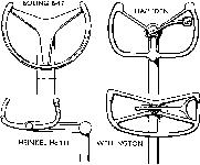
It is not, however, in the general scheme only that the Wellington fuselage differs from that of the Wellesley. The details themselves have been simplified considerably. Reference has already been made to the simple attachment of the geodesics to the tubular longerons. At the cross-over points, also, a different type of joint has been adopted. Where the two bars cross one another they are “halved together,” as we should have said in the old days of wood construction, and the joint is made by “butterflies” - rather like wing nuts - at right angles to one another, and having a bolt through their centres: there are gusset plates on the outside. The sketch on page d shows the arrangement. The geodesics themselves are of different form, with "hollow-backed" channel sections in place ot the plain straight-backed channels of the Wellesley.
It may be recollected that in the Wellesley one of the problems was to provide sufficient strength in the spar frames to resist the very high concentrated stresses transmitted from the spar flanges. In fact, these frames had to be so substantial that they weighed as much as the whole of the rest of the fuselage. In the Wellington a most ingenious arrangement has been adopted whereby the loads in the spar frames are greatly reduced, so that the frames can be made much lighter than they would otherwise be.
To understand the idea it is necessary to explain that the wing is of the three-spar type, with a single spar at the maximum depth of the wing section, and front and rear spars ot much smaller depth at the leading edge and towards the trailing edge. The central spar passes right through the fuselage (actually it is joined on the centre-line) and “floats” in it without touching it. The front and rear spars are attached to the sides of the fuselage or, more specifically, to the flanges of the spar frames by a form of cardan hinge which gives free movement about a vertical and a horizontal axis. From this it will be obvious that the central spar, which carries the wing bending loads, transmits no stresses to the fuselage structure direct.
The front and rear spars, because oi the cardan hinges, cannot transmit compressive loads arising from lift, but only those which are caused by wing drag, and which are relatively small. The wing lift is transmitted from the central spar to the front and rear spar root fittings and through them to the fuselage. The joint between main central spar and wing root rib occurs in the centre of the section, and not at the flanges, the tube of which, in fact, crosses those of the spar without touching them.
Although the spar frames have been relieved of loads in the matter just described, they still have to be of fairly substantial construction, as they do transmit the entire wing lift to the fuselage, and also serve as the basis for locating the whole fuselage structure. How the wing root fittings are attached to the flanges of these frames, and how the geodesics of the fuselage panels are secured to them, is shown in our sketches. Sheet-metal plates are first riveted to the flanges of those geodesics which cross the spar frames, and the plates are then bolted to the frames. In other words, the longerons are not attached to the spar frames direct, but via the geodesics. This arrangement results in very neat and simple joints. Except for the spar frames, and one or two others where local loads are heavy, all frames have disappeared from the Wellington fuselage.
The straightforward geodetic arrangement is interrupted by the bomb bay in the bottom of the fuselage. For a distance of twelve feet or more the continuity is interrupted to give way to a flat raised floor above the bay. The amount of reinforcement that has been needed to carry the stresses past this break is really surprisingly small. The floor members themselves, by the way, are of the same geodetic construction as the curved panels.
From the foregoing it may be gathered that the primary structure of the Wellington fuselage is very simple in its general theme, although the fact that the geodesics are of different lengths and different curvatures, according to their location in the structure, complicates matters somewhat metal structure at all. When the fabric tightens up after doping there is, of course, no tendency for the fabric to come away, other than that caused by airflow. Presumably this is not sufficiently great to cause any trouble, as one does not notice the fabric "flapping" in the way it can with some forms ot attachment. That it is indeed perfectly secure is shown by the fact that Wellingtons in service have been dived at about 300 m.p.h. without the fabric coming adrift.
Three-spar Wing
Reference has already been made to the fact that the wing of the Wellington is of the three-spar type. The main spar is placed in the deepest part of the wing section, approximately on the centre of pressure, and is in the form of a girder, with tubular booms and channel-section bracing members. In the inner portion of the wing the spar boom tubes are in duplicate, but towards the tip this arrangement changes to a single-tube boom. The inner spar portions on each side extend from the centre-line of the fuselage (there is a joint here) to the outer face of the engine nacelle. From this latter point to the tip the spar is in one unit, although a joint occurs where the change from double to single booms takes place. The tubular booms are machined on their outer faces, leaving thick walls where the geodesics and certain other attachments are made, and a thinner wall in between. This type of spar boom, somewhat costly to make, is an example of the care taken in avoiding all unnecessary weight in the Wellington. It might be mentioned that when the materials manufacturers have perfected a system now being evolved, a tapered spar boom of extruded section will be used. The spar booms in each section are not necessarily continuous. Where joints occur they take the form of bolted plate joints, the plates and tube being serrated so as to relieve the bolts of the shear loads. A similar system was employed in the Wellesley, but there the plates were horizontal whereas in the Wellington they are vertical.
Front and rear spars are of a totally different construction. They have webs of flat sheet and flanges or booms in the form of "open" tubes, as shown in one of the sketches. The use of this open tube greatly facilitates attachment of geodesics and other members.
As in the case of the fuselage, the wing panels are made up in jigs and are of large size. They are attached to the centre spar booms by means of forgings, and to the open tube booms of front and rear spars by simple fork ends. The fabric is attached to the flanges of the geodesics by wires on top ot the fabric surface, these wires being threaded through holes in small bolts, as shown in a sketch.
The mounting of the petrol tanks inside the wing provided something of a problem, owing to the considerable length of tanks involved. In the end a system was evolved which has proved satisfactory. The tank in each wing is divided into three independent units, mounted in the wing with single spigots at each extreme end, and with four rubber trunnion mountings between adjacent tanks. Each tank is connected to the next by external flexible pipes
What made the problem difficult was that it was not desired to cut into the geodetic wing construction, as this would have involved considerable weight, with openings for the tanks. Instead, the tanks are slid on wooden rails into the wing and fastened there. From this it follows that to remove a tank it is necessary to unship the wing.
At first sight it would appear that this was a bad feature in a military aircraft, the tanks of which might frequently get damaged. Actually, the outer wing portions are attached to the engine nacelles by 26 screws, which can be quickly dealt with by a brace similar to that used for removing the wheels of a car. By way of an experiment a wing was unshipped, the tanks changed, an A.I.D. inspection carried out, and the wing put back again ready for flight in three hours.
It is much to be regretted that details of certain tests made cannot be published. They relate to the extent to which the geodesics can be damaged without endangering the strength of the wing, and show some very good results. In this connection one may recall the "basket" masts used on certain ships of the United States Navy some years ago. Tests of these showed that a large number of the geodesics could be shot away without bringing the mast down. Similar results were obtained in tests on a Wellington geodetic wing. It seems almost impossible so to damage such a wing that the machine could not be flown home safely.
VICKERS WELLINGTON I
Two Bristol Pegasus XVIII Engines
Span 86ft. 2in.
Length (guns extended) 64ft. 7in.
Track 20ft. 4in.
Wing area 750 sq. ft.
Wing loading 29-6 Ib./sq. ft.
Normal gross weight 24,850 lb.
Top speed 265 m.p.h. at 17,000 ft.
Maximum range 3,200 miles at 180 m.p.h.
Service ceiling 26,300 ft.
Climb to 15,000 ft. 18 min.
Flight, November 1939
Britain's Military Aircraft
A Survey of Our Service Machines
VICKERS ARMSTRONGS
The Vickers Wellington twin-engined, long-range bomber is being produced in large numbers at the Vickers works. This machine is of geodetic construction and has fabric covering. With two Bristol Pegasus XVIII engines a top speed of 265 m.p.h. is attainable at 17,000ft. Other products of the Vickers Armstrongs group in service with the R.A.F. are the Supermarine Stranraer twin-engined biplane flying boat and the Walrus three-seater amphibian.
Vickers Armstrongs, Ltd.., Vickers House, Broadway, Westminster.
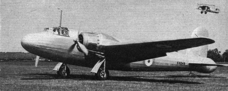
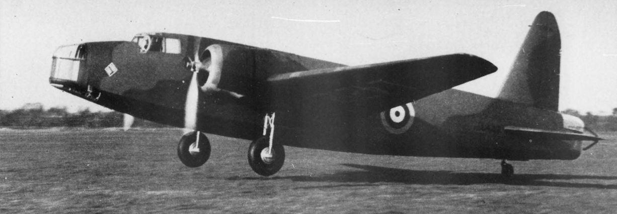
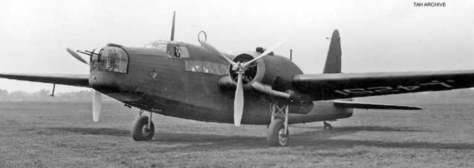
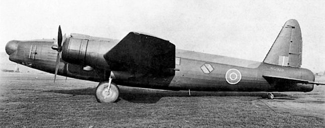
Prototype
Прототип Vickers B.9/32 (K4049) совершил первый полет в Бруклэндс 15 июня 1936 года. После того, как он разбился в апреле 1937 года, в конструкцию самолета пришлось внести множество изменений.
The B.9/32 Wellington prototype, K4049, before delivery to Martlesham Heath.
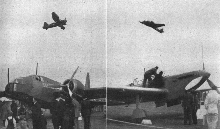
OVER-RIDE: The new Vickers "geodetic" medium bomber with its twin Pegasus engines receiving over-ride boost, sails up like a fighter. This machine represents a new class of bomber, the development of which is receiving close attention in this country.
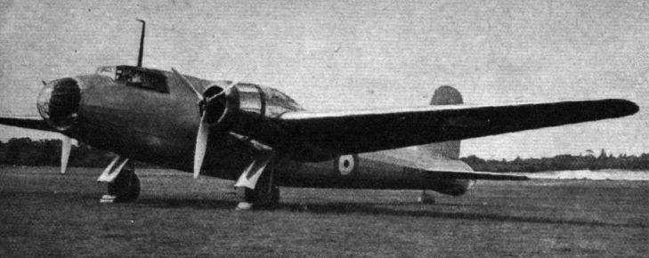
The Wellington prototype shows off its clean lines in the air. The nose was still fabric-faired when this photograph was taken.
THE VICKERS WELLINGTON, fitted with “Bristol” Pegasus engines, is a twin-engined, mid-wing monoplane of Vickers "geodetic" construction; with cantilever wings, retractable undercarriages, patent ailerons, split flaps and controllable-pitch airscrews. Designed for fast long-range bombing or service transport, the normal crew numbers four, including two pilots. No performance figures are available for publication. In production for the Air Ministry by Vickers (Aviation) Ltd.
The twin-engined, so far un-named machine, have Bristol Pegasus engines and is of "geodetic" construction.
The B.9/32 Wellington prototype, K4049, before delivery to Martlesham Heath. The aircraft is seen flying at the RAF Display in June 1936, only days after its first flight, made from Brooklands on June 15, and is numbered 7 for exhibition in the Hendon new-types park.
The Vickers medium bomber.
A medium bomber of impressive appearance and performance, the first Vickers twin-engined "geodetic" monoplane has been adopted by the R.A.F. under the name Wellington.
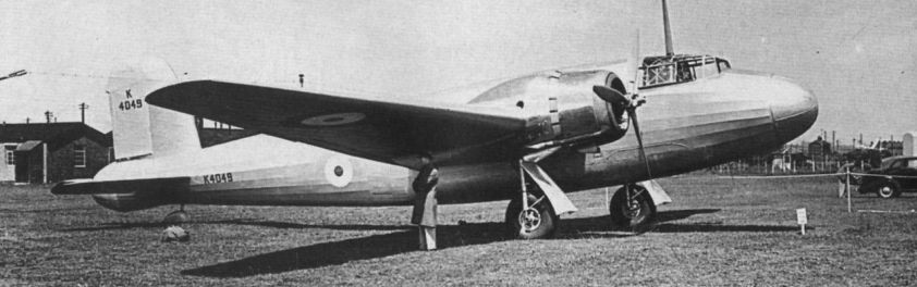
The Vickers B9/32 K4049 at Brooklands, June 1936, wearing the Hendon 'New Types Park' number' T in front of the fuselage roundel.
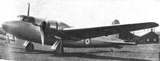
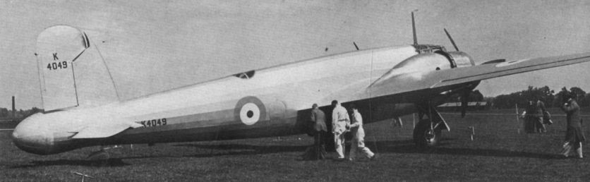
The Wellington prototype photographed at Brooklands on June 30, 1936, at a pre-Pageant display of Vickers aircraft.
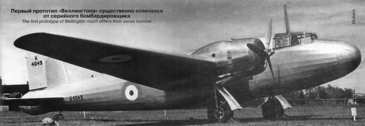
Первый прототип «Веллингтона» существенно отличался от серийного бомбардировщика
The Wellington prototype photographed at Brooklands on June 30, 1936, at a pre-Pageant display of Vickers aircraft. Note the uncompleted dorsal turret and the fairings over the nose and tail turret positions.
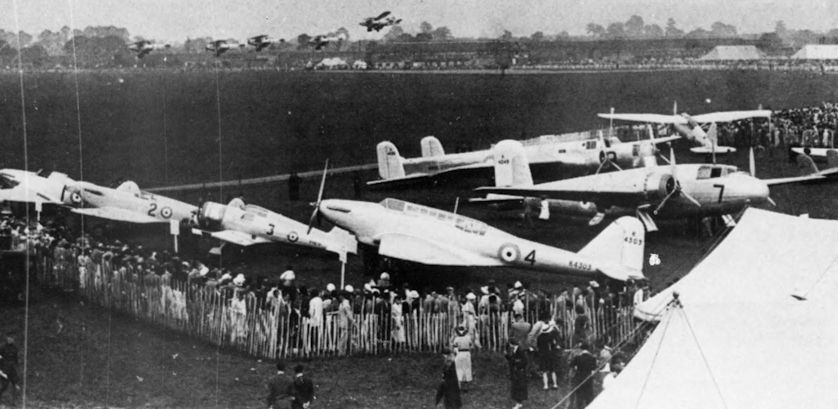
The shape of wings to come. Monoplanes fill the new types park at the 1936 pageant.
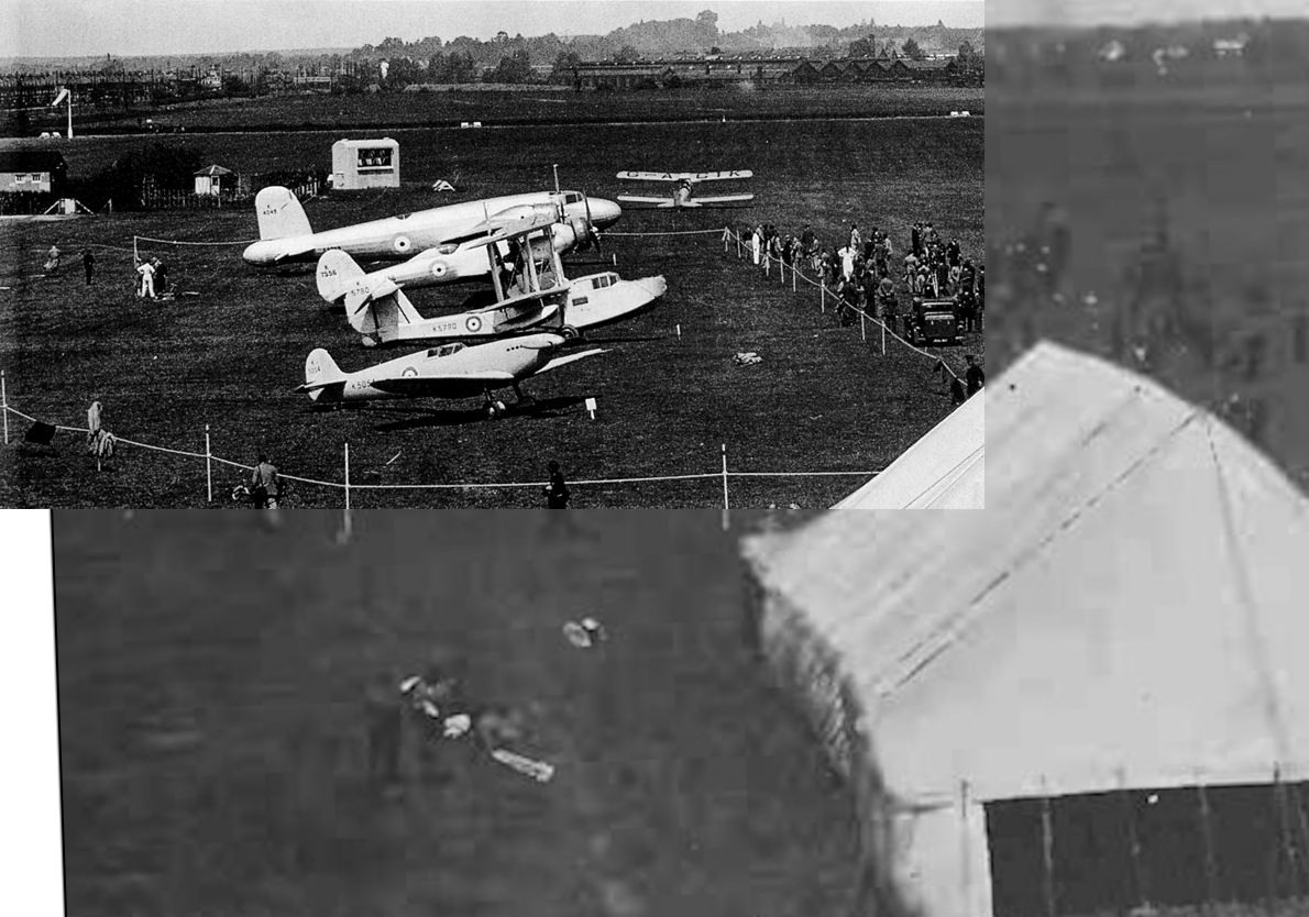
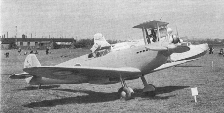
K5054 был впервые показан 300 приглашенным гостям 18 июня 1936 года на демонстрации самолетов фирмы "Vickers" в Истли, На снимке: K4049 - прототип бомбардировщика В.9/32 (позднее служившего под именем Wellington); K7556 - предсерийный бомбардировщик Wellesley и K5780 - девятая серийная амфибия Walrus. В 1938 году "Supermarine Aviation Works (Vickers) Ltd" и ее головная компания "Vickers (Aviation) Ltd of Weybridge" объединились в фирму "Vickers-Armstrong Limited".
Supermarine Spitfire prototype on view to the public in 1936 alongside a Walrus, the prototype Wellesley and prototype Wellington.
Another view of K5054 at the pre-Pageant show at Brooklands on June 30, 1936. Behind it are Supermarine Walrus I K5780, Vickers Wellesley prototype K7556 and Vickers B.9/32 prototype K4049, later to become the Wellington.
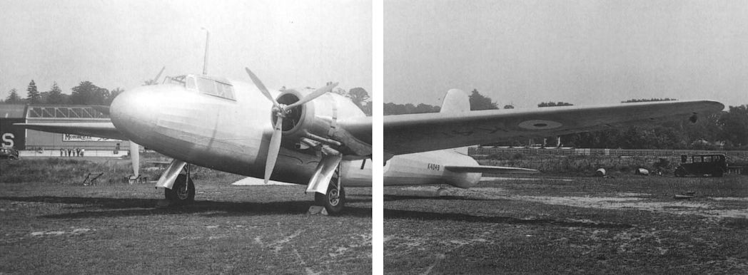
The Vickers B9/32 with glazed areas in the nose and tail.
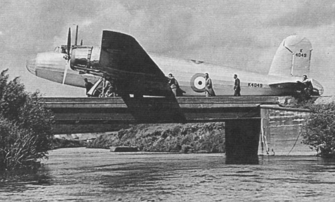
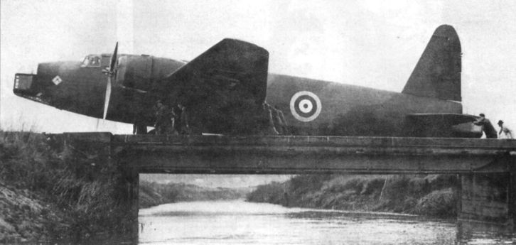
Perhaps the most famous B.9/32 photograph of all, taken as the prototype was pushed across the bridge spanning the River Wey at Brooklands.
The Pegasus-powered Vickers Wellington I prototype. Production versions of this extremely efficient medium bomber are likely to differ in certain respects.
The B.9/32 running-up its engines beside the Vickers factory at Brooklands.
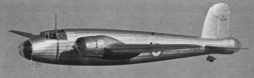
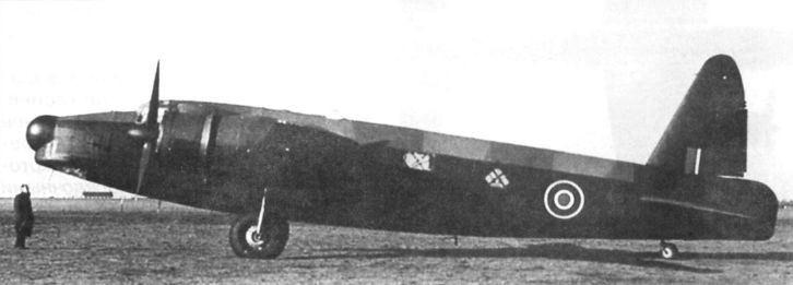
The Wellington flying early in 1937. The original stubby fin and rudder were completely redesigned for production aircraft. Note that the nose glazing has been fitted. It will be noted in the view that crankcase cowlings of a type which was popular in the U.S.A. some years ago have been fitted experimentally.
Первый прототип «Веллингтона» в полете
K4049 in flight. The aircraft was destroyed on April 19, 1937 at Waldringfield, not far from Martlesham Heath.
Mk I
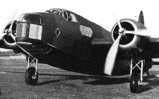
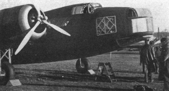
GEODETIC TWIN: The production-type Vickers Wellington I (two Pegasus XVII) built, like the Wellesley, on the geodetic principle. Part of the construction can be glimpsed through the Perspex of the bomb-aimer's window.
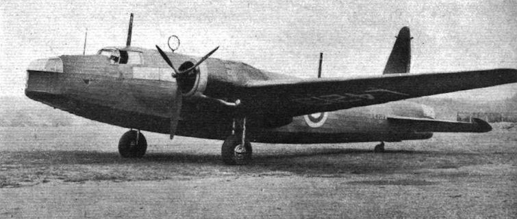
GEODETIC BOMBER: The production-type Vickers Wellington I medium bomber awaiting tests at Weybridge.
One of the neatest large undercarriages yet seen that of the Vickers Wellington twin-engined bomber.
IN SERVICE SOON: A new view of the Pegasus-engined Vickers Wellington I medium bomber, which will before long be standard equipment in the R.A.F. There is a Nash and Thompson multi-gun turret in the nose and stern, and a third gun position amidships.
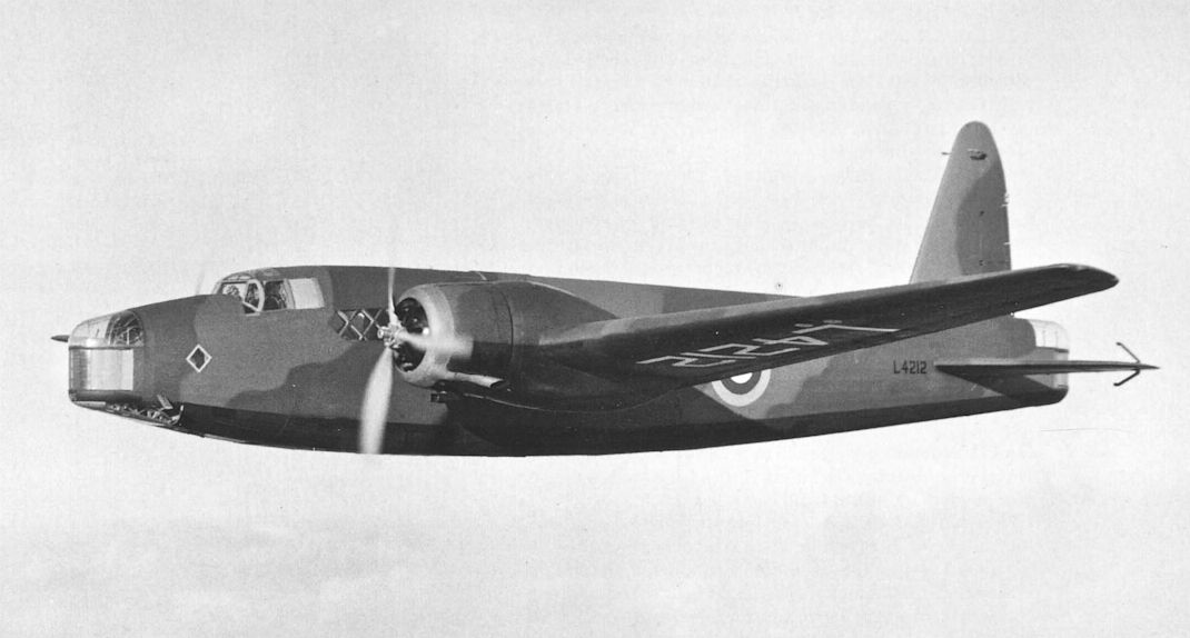
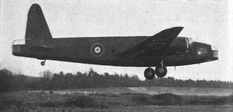
View of the prototype Wellington Mark I, L4212, first flown on December 23, 1937, from Brooklands with “Mutt" Summers in command. It was later converted to DWI status.
View of the prototype Wellington Mark I, L4212, first flown on December 23, 1937, from Brooklands with “Mutt" Summers in command.
The much-discussed Vickers Wellington bomber with Pegasus engines is the second machine of geodetic construction to be adopted. The Rolls-Royce Merlin and Bristol two-row Hercules are alternative power units. Nose and tail turrets are installed.
DUCAL DIGNITY: The first production-type Vickers Wellington I <...> bomber built on the geodetic principle and powered with two Bristol Pegasus XVII radials with two-speed blowers. The transparency of the <...>nd tail turret roofs in this view gives a false impression of marring the fine lines of the fuselage which, incidentally, <...> revised since the prototype appeared.
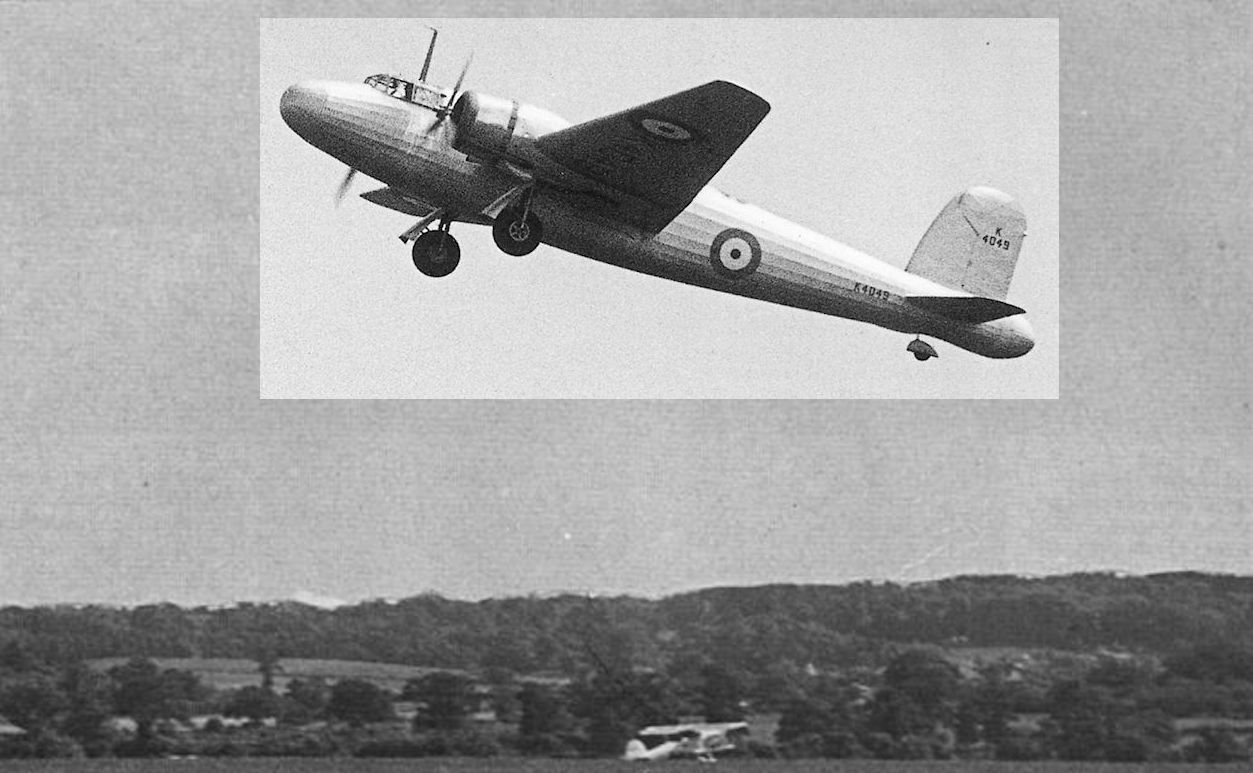
The prototype Wellington Mk I bomber, L4212, taking off from Brooklands in December 1937. This aircraft was a complete redesign of the B.9/32, originally called the Crecy but changed to Wellington in September 1936.
The Vickers Wellington is built on the geodetic principle of construction, which confers high load carrying capacity and long range.
The protoype Wellington, Mk 1 L4212, was first flown on December 23, 1937 from Brooklands and is seen landing there in January 1938.
“This desirable Tudor residence” is suggested by the geodetic window-panes of the Vickers Wellington I medium bomber (two Bristol Pegasus with two-speed superchargers), but the performance is anything but medieval. This, the production job - photographed by Flight Brooklands last week - has been very considerably cleaned-up as compared with the prototype which, it may be remembered, had an oddly insect-like bulge at the tip of the tail. The unfamiliar fittings within the collector rings are Vickers crankcase cowlings.
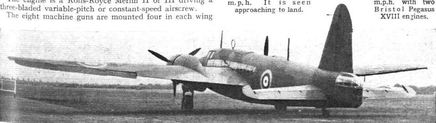
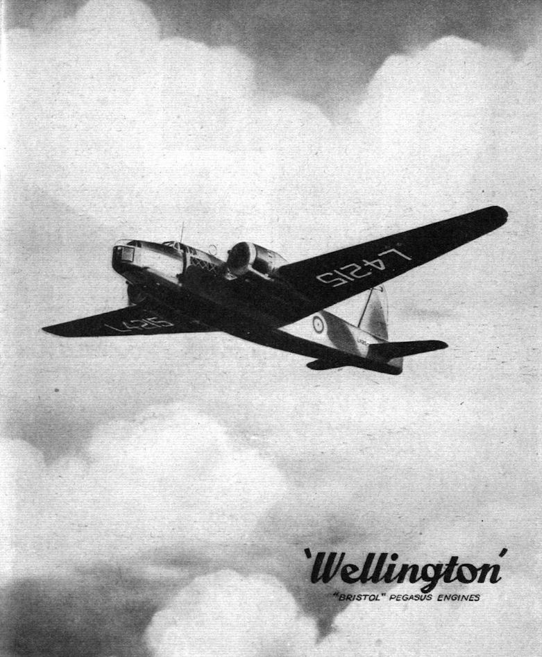
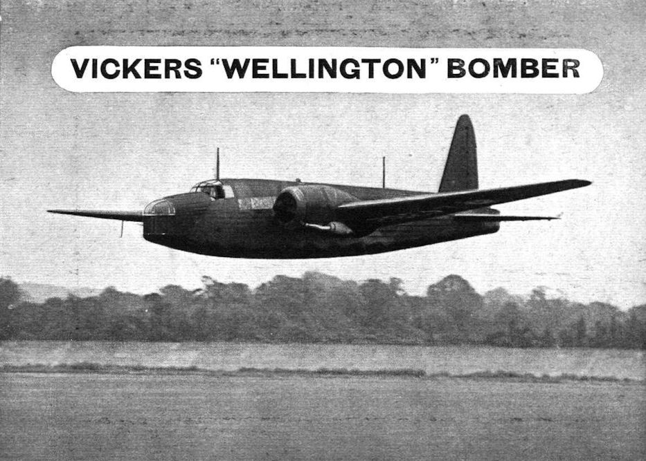
The Vickers "Wellington" Long-range Bomber Monoplane (two Bristol "Pegasus" engines).
A Vickers Wellington long-range bomber of the type adopted by the R.N.Z.A.F.
FIRST FROM CHESTER: This perfectly normal Wellington is of special interest because it was assembled and delivered to the Service only eight months after work had been started on the building of the new Vickers-Armstrong works at Broughton, Chester.
VICKERS WELLINGTON long-range bombers (Pegasus) awaiting test at Brooklands. The crankcase cowlings are interesting.
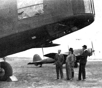
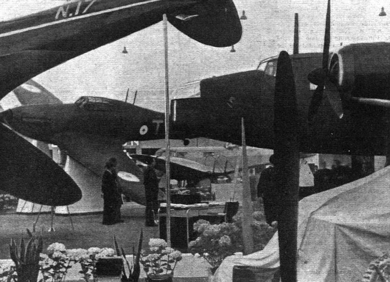
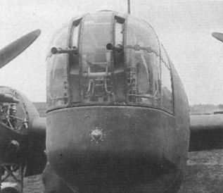
The Air Minister is seen under the imposing nose of a Wellington, with a Wellesley in the background. On the left is Sir Robert McLean, chairman of Vickers Aviation Ltd.
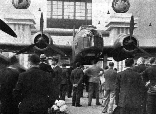
The Wellington I, on the Air Ministry stand, is the largest aircraft in the Show
A British quartet impressively grouped: the Speed Spitfire, Hurricane, Oxford and Wellington.
Wellington Is of 149 Sqn. Based at Mildenhall; the squadron first equipped with Wellingtons in January 1939 and began night bombing in May 1940.
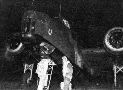
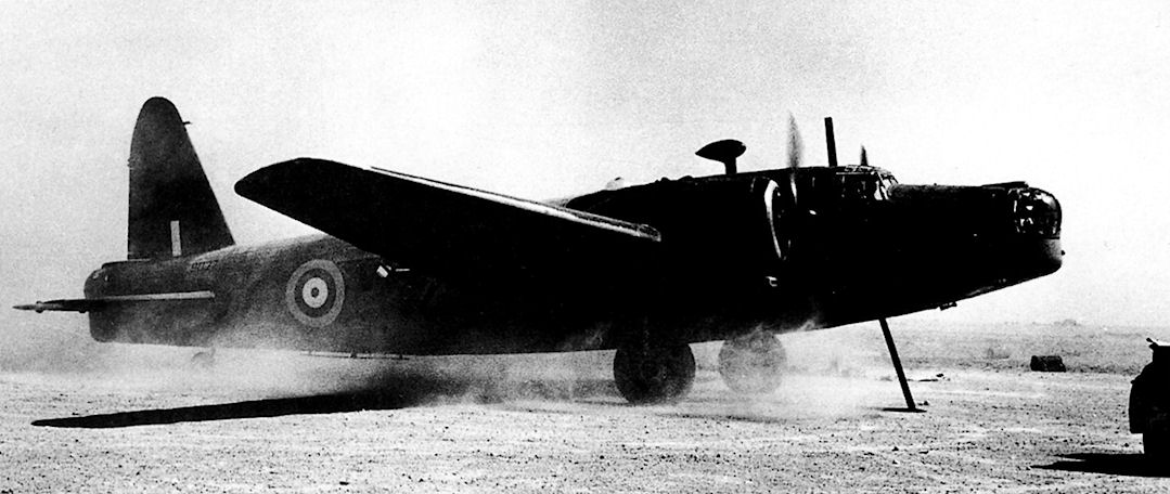
As the sun sets the night-bombing Wellingtons are dragged from their hangars.
The Vickers Wellington I bomber does 265 m.p.h. with two Bristol Pegasus XVIII engines.
Первый серийный «Веллингтон» Mk.I на мосту через реку Вей по дороге на аэродром Бруклендс
All in the picture: Westland Lysander over Vickers Wellington, and Bristol Blenheim over Fairey P.4/34.
Boarding an Eastland Wellington at Stradishall prior to a bombing raid over “blacked out” Westland.
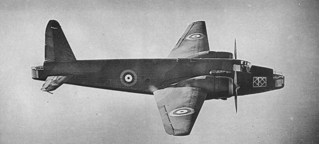
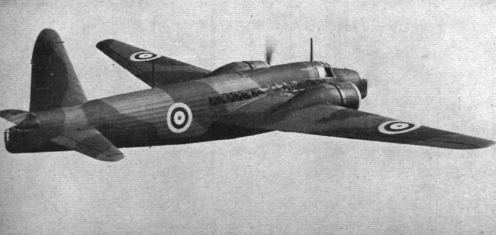
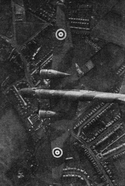
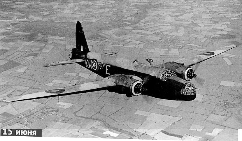
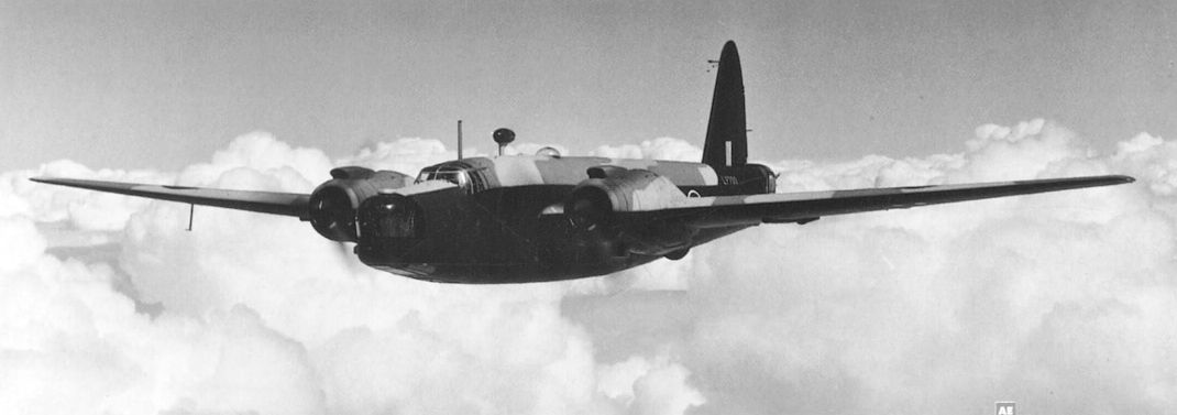
This aerial photograph gives a good idea of the Wellington's external appearance. It also shows the excellent provision for admitting daylight.
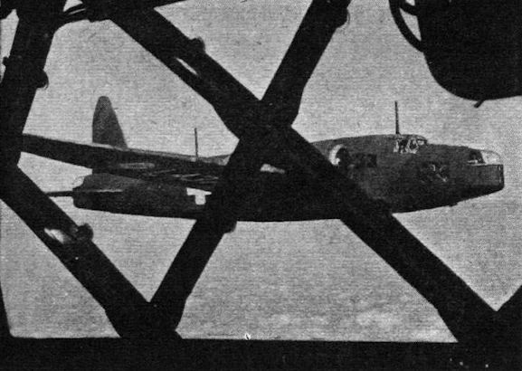
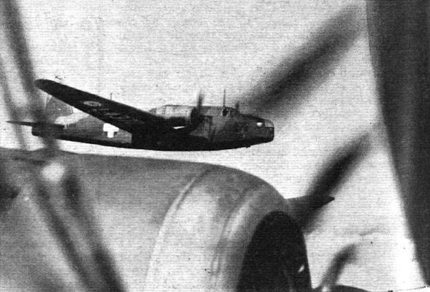
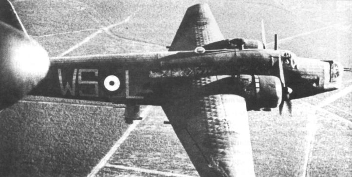
A "friendly" Wellington as seen through the geodesics of a consort. The white cross was the distinguishing mark.
Another intimate glimpse of a “friendly” Wellington over the nacelle.
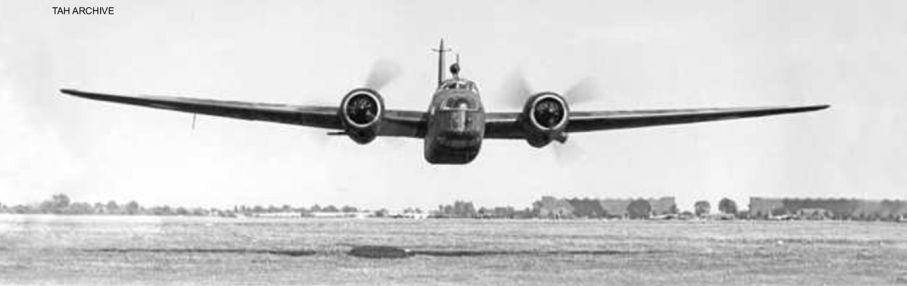
Heads up! A Wellington I of No 11 OTU performs a lively low-level pass over the grass at the unit’s base at Bassingbourn in Cambridgeshire. One of the RAF’s newer bases, Bassingbourn opened in March 1938 and was the most easterly of Bomber Command’s OTUs, and was thus subject to frequent attacks from Luftwaffe intruders.
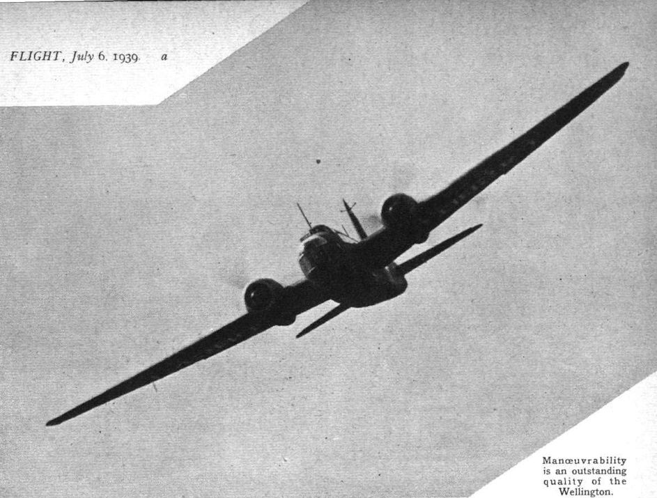
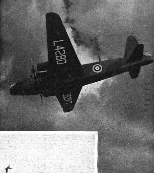
Manoeuvrability is an outstanding quality of the Wellington.
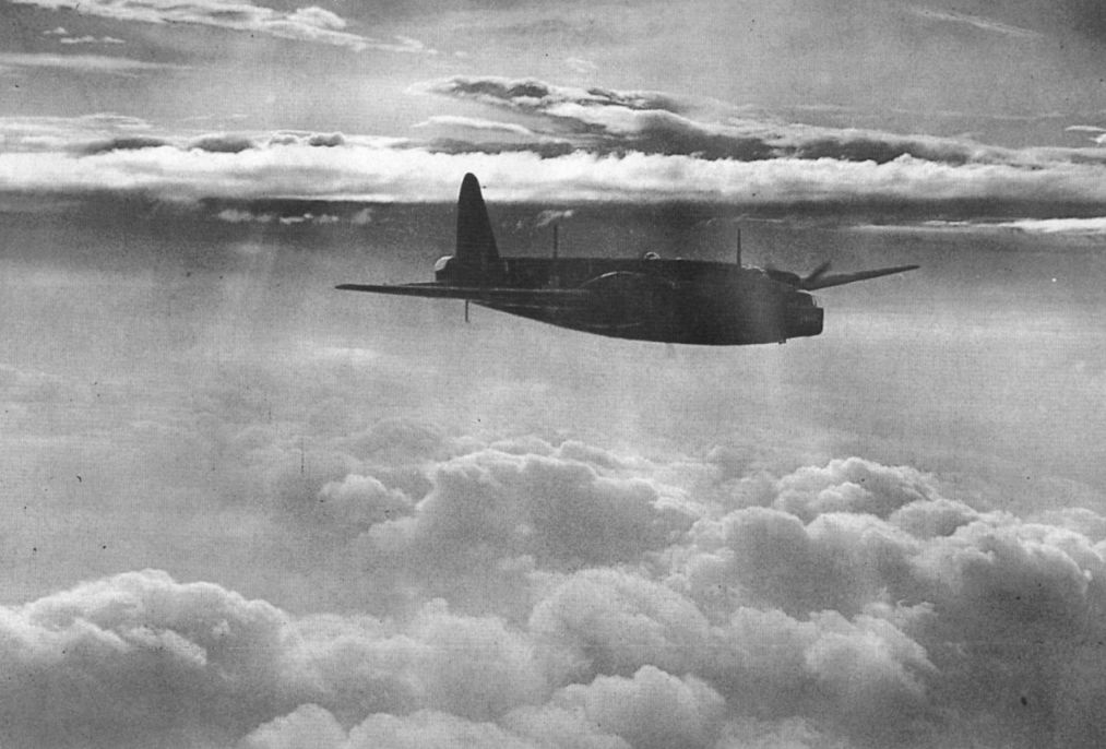
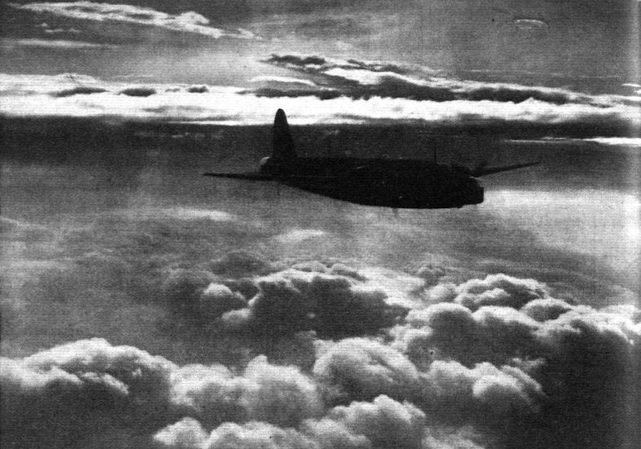
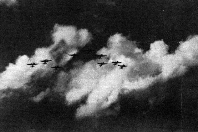
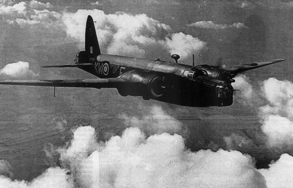
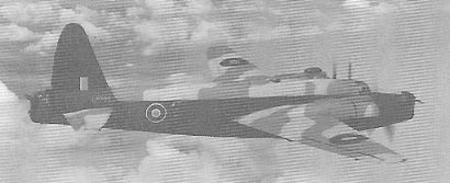
"Some of the longer reconnaissance flights - of 1,000 miles or so - have been carried out at night under weather conditions of great difficulty." A Vickers Wellington above the clouds.
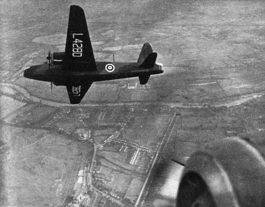
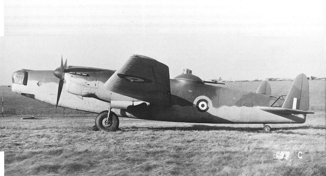
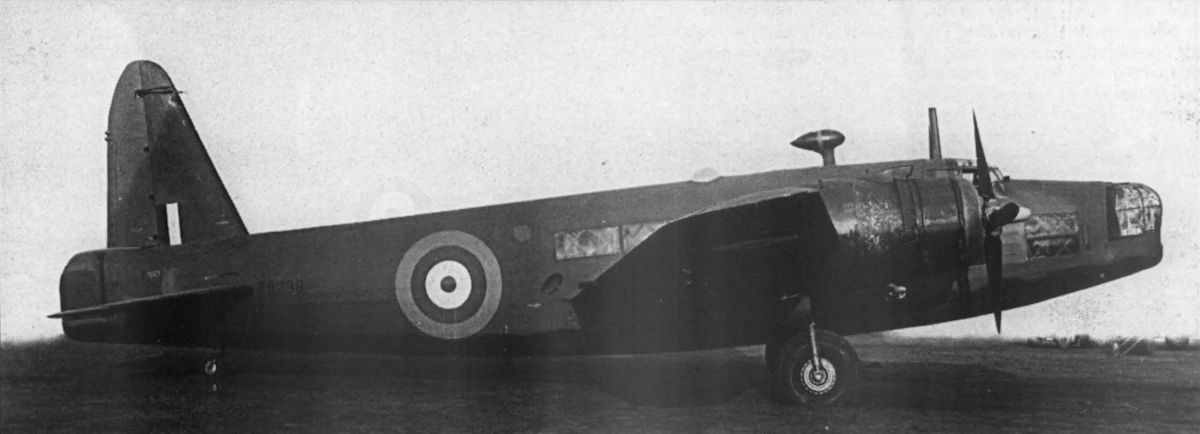
Первыми серийными Wellington стали 180 самолетов модификации Mk I (заказ размещен в августе 1936 года). Большинство оснащались двигателями Bristol Pegasus XVIII. Первые машины поступили в 99-ю эскадрилью в октябре 1938 года. Изображенный L4280 был передан 148-й эскадрилье в марте 1939 года. Среди первых самолетов Wellington были шесть машин, заказанных новозеландскими ВВС, но с началом войны все поступили в британские ВВС.
GEODETICS ON THE GRAND SCALE: Flt. Lt. J. Summers, chief test pilot to the Vickers-Armstrong group, shows off some of the finer points of the Wellington long-range bomber near Weybridge. Wellingtons are coming through at a highly creditable rate and are taking up the brightly burning torch of geodesy from the Wellesley. The engines are Bristol Pegasus.
ENGLISH as the THAMES. A Vickers Wellington bomber - Pegasus-powered - on test near its home aerodrome; those who know their Thames will see exactly where. The Wellington is built on the exclusive geodetic system and ranks as one of the world’s most formidable bombers.
A "friendly" Wellington slips low over East Anglia. These non-combatant machines were included for their "nuisance value."
Vickers-Wallis geodetic construction gives the Vickers Wellington great weight-lifting powers. The engines may be of the Bristol Pegasus, Bristol Hercules, or Rolls-Royce Merlin type.
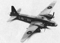
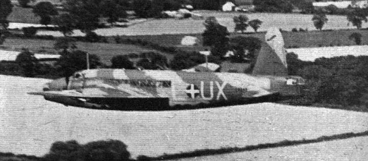
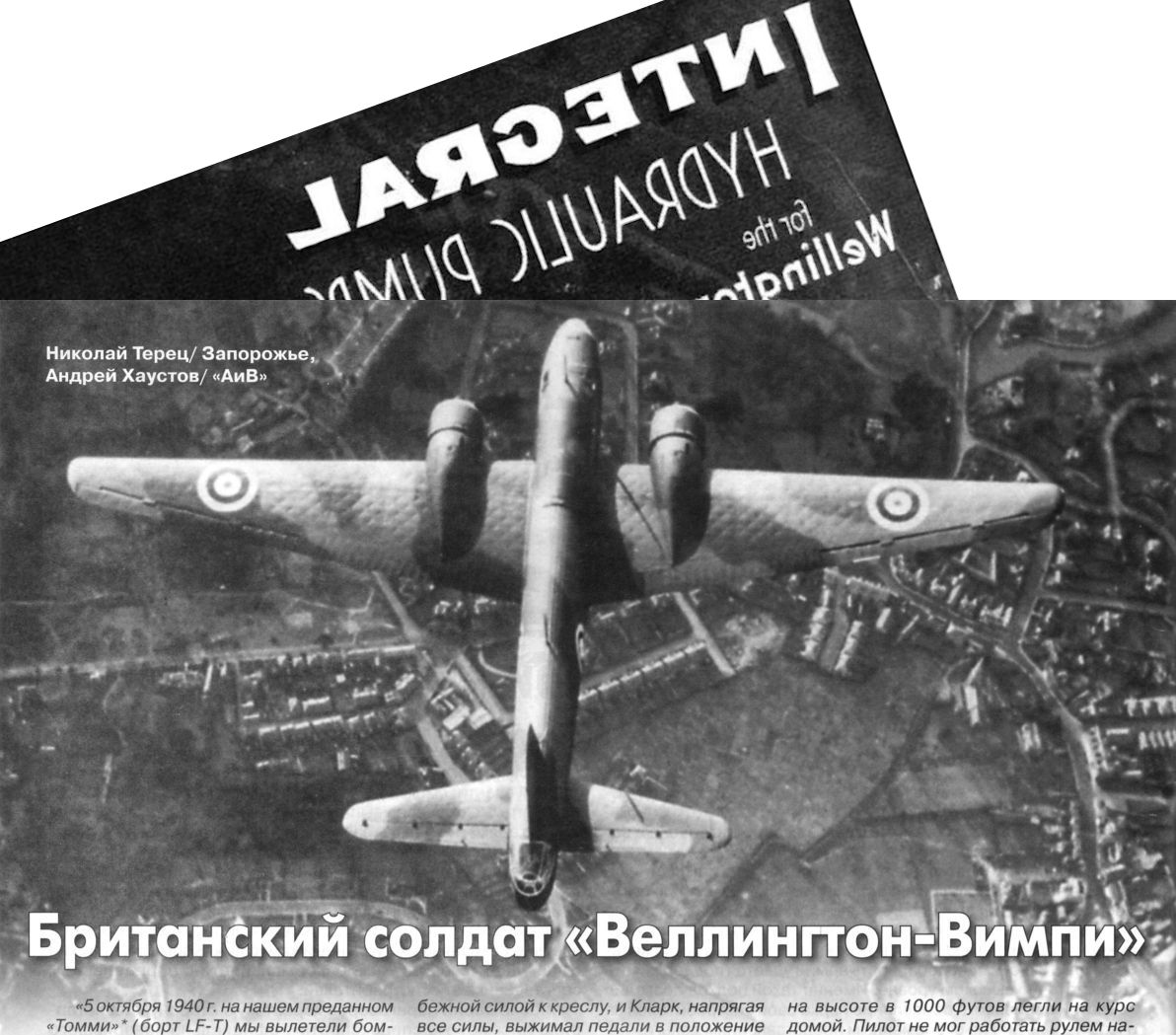
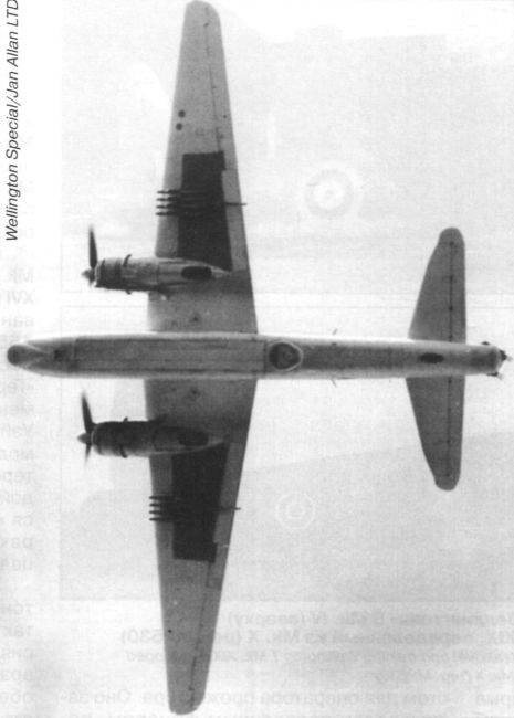
PROTECTIVE COLORATION: A convincing plan view of a Vickers Wellington (two Bristol Pegasus) adopting the mantle of suburban respectability.
A Vickers Wellington show in a striking fashion the effectiveness of its camouflage markings.
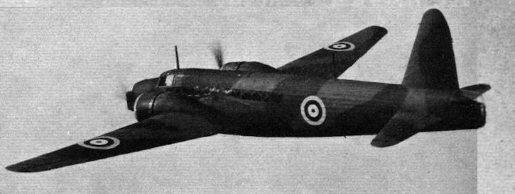
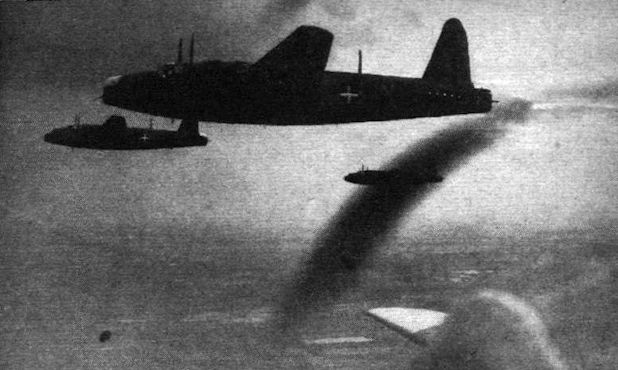
DISTINGUISHED SERVICE has already been done by Vickers Wellington I bombers, two of which aircraft are seen over the sea in the Flight photograph. The Wellington does 265 m.p.h. and is the biggest of the R.A.F.’s landplane bombers.
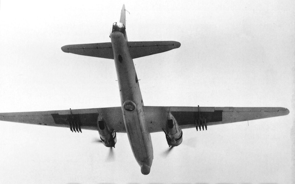
A DANGEROUS VIEW for the pilot of an “E.A.” to have of the Vickers Wellington bomber is that shown here. The tail gunner can easily bring the stern armament to bear.
HOMING: After a long night’s flying a Vickers Wellington bomber approaches its aerodrome as the early sun tinges the clouds below. Soon the pilot will switch the blowers of his two Pegasus engines into low gear and descend.
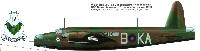
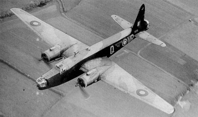
В первые два года Второй мировой войны самолеты Wellington являлись наиболее результативными британскими бомбардировщиками. Их геодезическая конструкция стала визитной карточкой компании «Vickers» и была предложена конструктором компании Барнсом Уоллисом. На фотографии представлены самолеты Mk 1 с эмблемой «летучая мышь» IX эскадрильи британских ВВС.
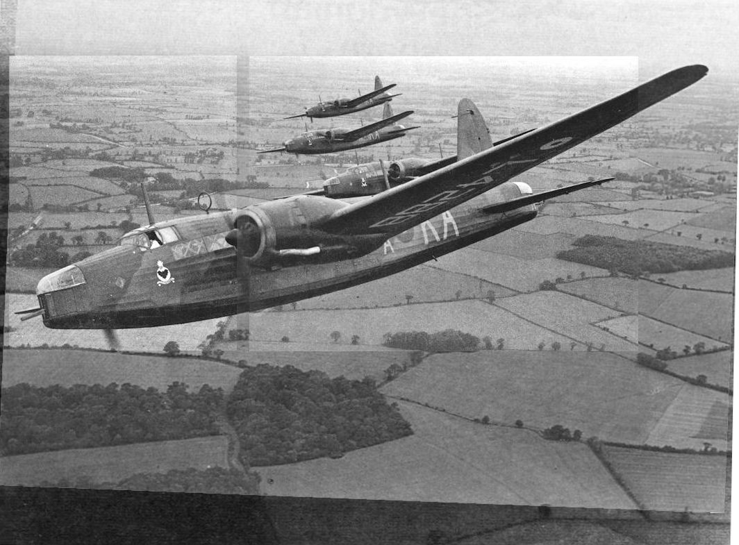
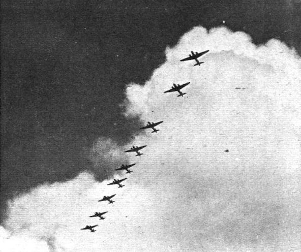
Боевой порядок Wellington Mk I из 9-й эскадрильи британских ВВС - снимок сделан на учении в 1939 году. 9-я эскадрилья воевала на Wellington до августа 1942 года, когда ее перевооружили на Lancaster Mk I.
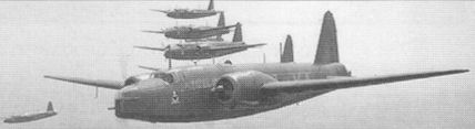
TAKING-UP FORMATION: Especially during the air exercises last week-end, quite large formations of Wellingtons have been in evidence. Even a quartet of these impressive aeroplanes makes an inspiring spectacle
Wellington I L4288 leads three other 9 Sqn Wellingtons over the English countryside for the benefit of Charles E. Brown’s camera in 1939. L4288 crashed near Honington on October 30 of that year after a mid-air collision. Note the single front gun with its cover fitted.
«Веллингтоны» Mk. I из 149-й эскадрильи над Парижем в ходе визита в День взятия Бастилии. 14 июля 1939 г.
"SECRETS TRAVEL FAST IN PARIS" - Napoleon. Wellingtons over Paris during the recent "flag-showing" visit of British bomber squadrons to France. Those acquainted with the French capital will recognise the Invalides in this impressive photograph. The picture was secured from another Wellington in the formation, and the “dish-pan” cowling of one of the Pegasus XVIII engines can be seen.
“Escadrille de 9 avions Vickers-Wellington - vol en echelon refuse vers la droite.”
Экипажи 9-й эскадрильи отрабатывают на своих «единичках» групповую слетанность. Лето 1939 г.
10 июля 1939 года данные Wellington Mk I из 9-й (бомбардировочной) эскадрильи (АБ Страдисхолл) вместе с машинами из еще четырех эскадрилий были переброшены во Францию. На тот момент Wellington был лучшим самолетом британского Бомбардировочного командования.
Mk.IC
Along with their fighter counterparts, the RAF’s bombers were also fitted with 0-303in machine-guns. After early wartime operations revealed that the Vickers Wellington had inadequate defensive firepower, the Mk III was fitted with eight 0-303in guns, the new Frazer-Nash FN20 tail turret incorporating four 0-303ins instead of just two.
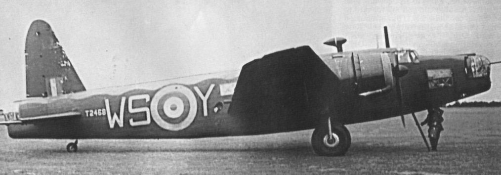
The brand new Vickers Wellington was a Mk IC, T2468 Y-Yorker. She was a beauty!
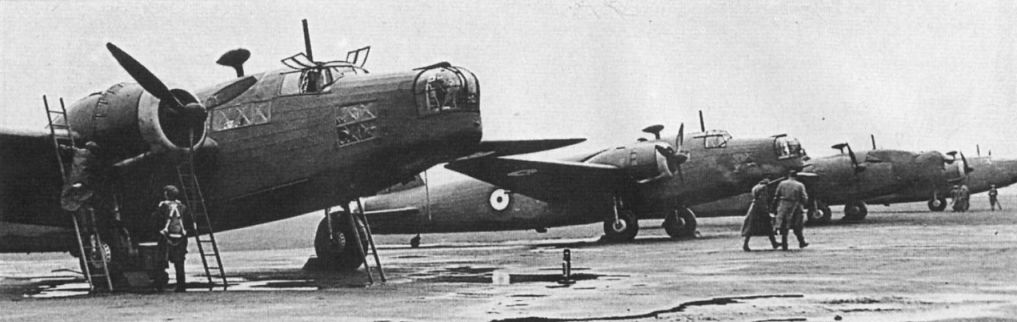
Part of a batch of Wellingtons fresh from the production line in early 1940, with armament still to be installed.
An experimental Wellington with Bristol Hercules sleeve-valve engines.
25-26 августа 1940г.: в эту ночь 43 самолета Бомбардировочного командования выполнили первый налет британской авиации на Берлин. Среди них были бомбардировщики Vickers Wellington из 143-й эскадрильи.
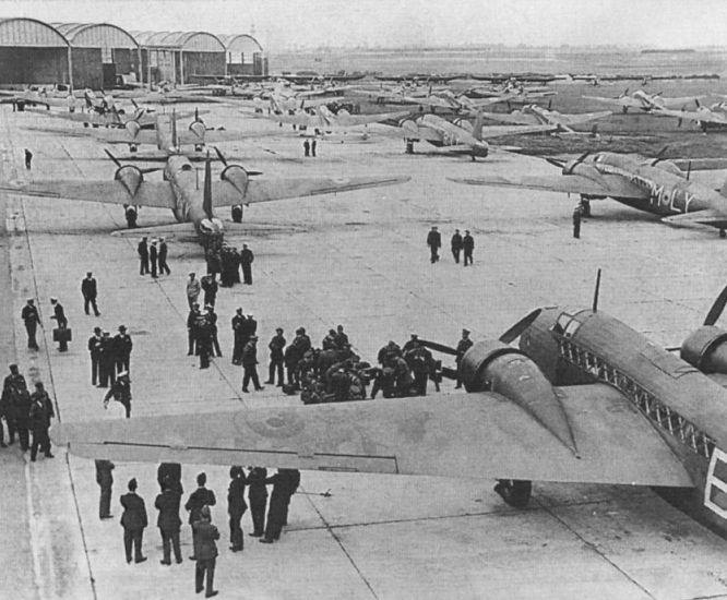
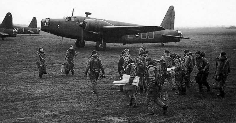
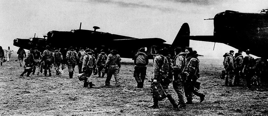
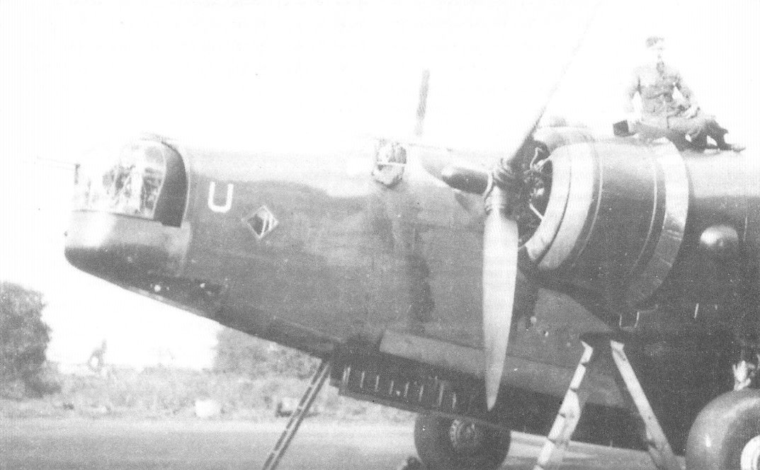
Экипажи Vickers Wellington 149-й эскадрильи, базирующейся в Милденхолле, графство Суффолк, садятся в свои самолеты для ночного налета на Германию. Эта эскадрилья сыграла заметную роль в первых подобных рейдах.
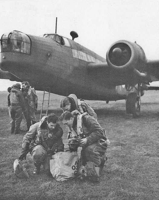
Экипаж одного из ранних Wellington готовится к очередному вылету. Бортстрелки носили тяжелые утепленные штаны и куртки из овчины. Позже многие ранние Wellington Mk I были сняты британцами с фронта и переоборудованы в транспортные самолеты. В частности, такие 18-местные машины использовались на Ближнем и Среднем Востоке.
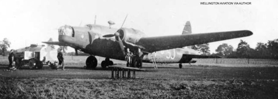
A rare photograph of a Wellington IC of “E” Flight, No 21 Operational Training Unit (OTU), based at Moreton-in-Marsh in Gloucestershire. After commencing flying operations in the spring of 1941, No 21 OTU was tasked specifically with training crews for the Middle East. Note No 21 OTU’s “SJ” code letters on the fuselage.
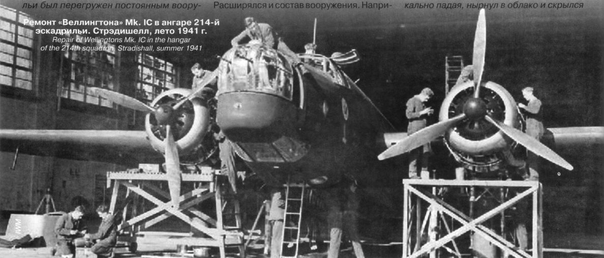
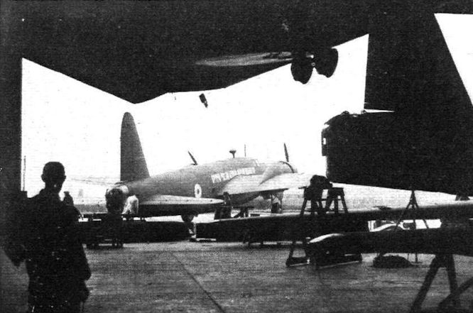
Ремонт "Веллингтона" Mk.IC в ангаре 214-й эскадрильи. Стрэдишелл, лето 1941г.
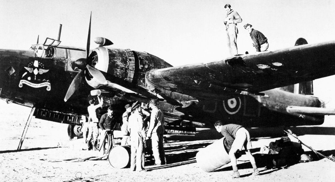
Подвеска бомб под «Веллингтон» Mk. I
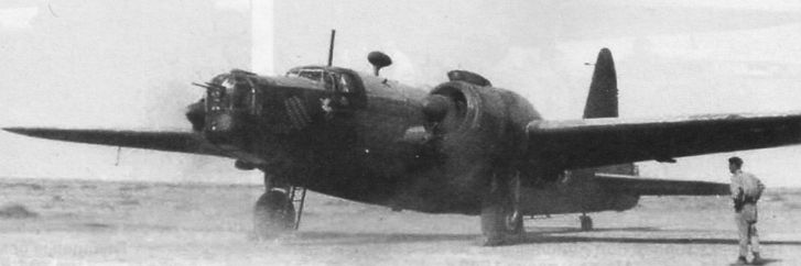
Основу британской бомбардировочной авиации в районе Западной пустыни составляли Vickers Wellington. На снимке: Mk 1С из 37-й эскадрильи, одной из шести вооруженных Wellington эскадрилий, дислоцировавшихся в регионе. Эти самолеты внесли большой вклад в нарушение коммуникаций противника, уничтожение баз, складов и конвоев.
Yet one more Wellington is taken from the erecting shops to the aerodrome for flight tests.
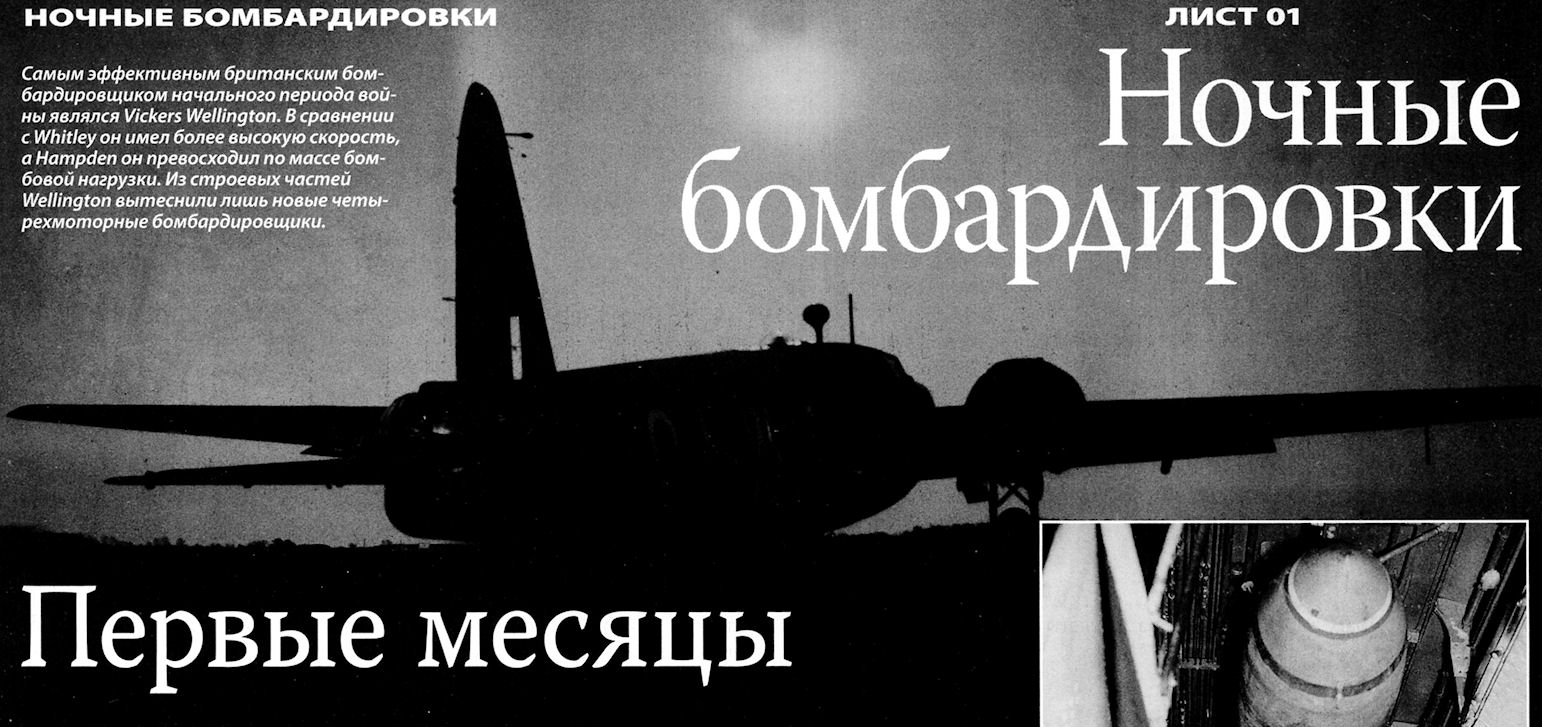
Самым эффективным британским бомбардировщиком начального периода войны являлся Vickers Wellington. В сравнении с Whitley он имел более высокую скорость, a Hampden он превосходил по массе бомбовой нагрузки. Из строевых частей Wellington вытеснили лишь новые четырехмоторные бомбардировщики.
Служба самолета в Бомбардировочном командовании в метрополии наиболее известна и "перекрыла" вклад Wellington в действиях на Среднем Востоке. Изображенный Mk 1C (из 70-й или 148-й эскадрильи) готовится на расположенном в пустыне аэродроме к очередному вылету, 1942 год. Обратите внимание - с самолета снято все оборонительное вооружение, это сделано для экономии массы и ввиду отсутствия угрозы со стороны истребителей противника в ходе ночных рейдов над пустыней.
«Веллингтон» Mk. IA в полете с выпущенной выдвижной подфюзеляжной турелью FN25
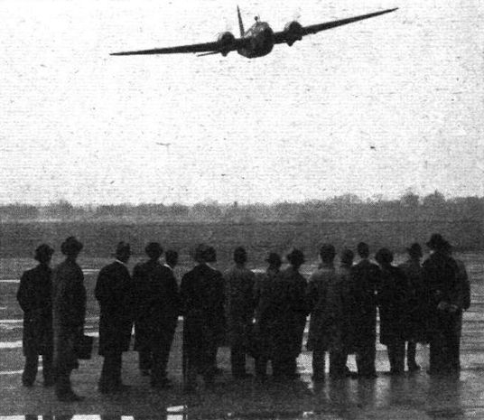
“Somewhere in England.’’ Foreign Press representatives interested in a demonstration of the Vickers-Armstrongs Wellington.
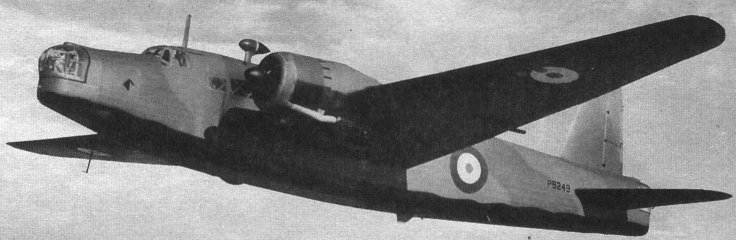
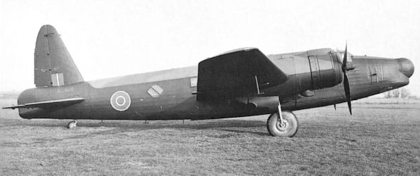
«Веллингтон» Mk. IC стал первым крупносерийным самолетом этого типа
Mk IC P9249 was allocated to 38 Sqn. It crashed on the approach to Marham in June 1940.
«Веллингтон» Mk. I поздних серий выпуска с блистером астролюка. На опознавательные знаки нанесена маркировка, применяемая на учениях в августе 1939 г.
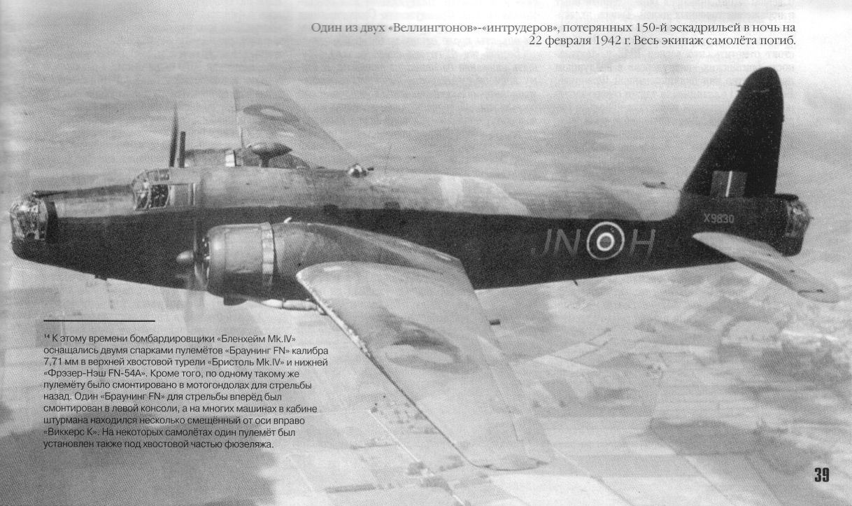
Один из двух "Веллингтонов"-"интрудеров", потерянных 150-й эскадрильей в ночь на 22 февраля 1942г. Весь экипаж самолета погиб
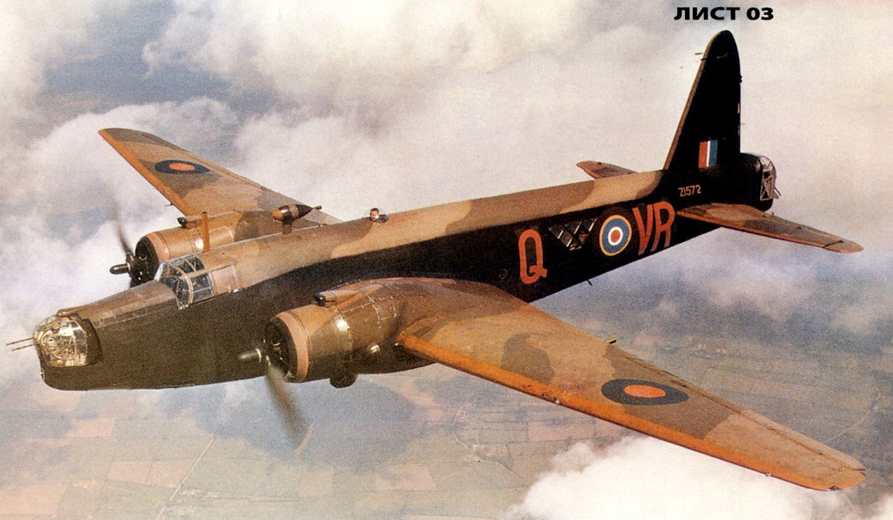
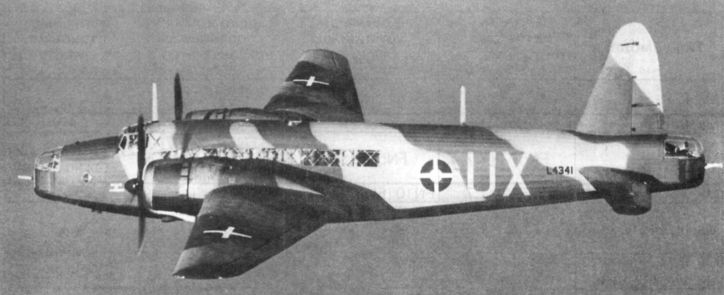
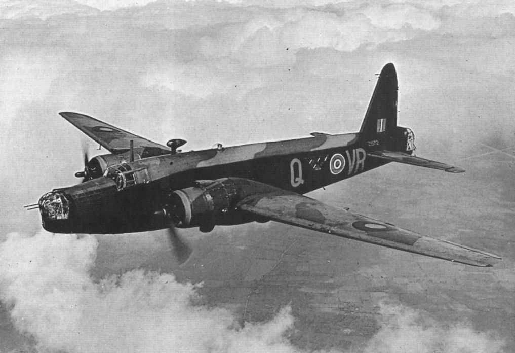
Wellington IC Z1572 of 419 Squadron in standard night camouflage.
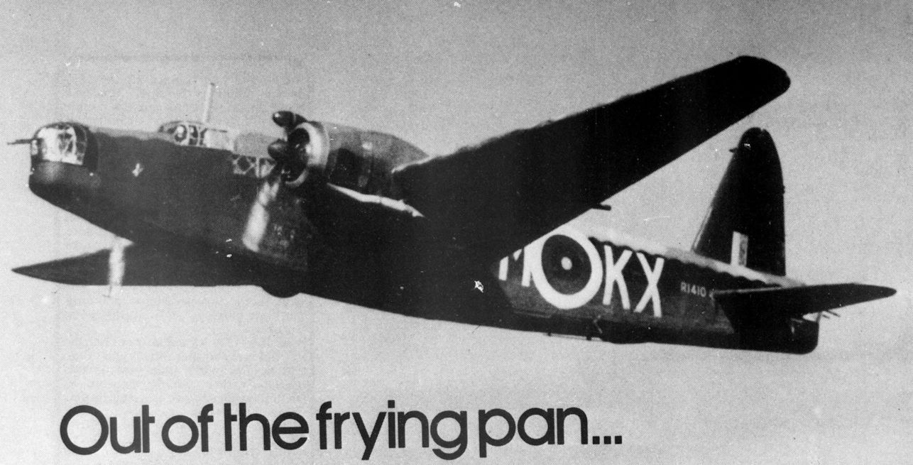
Wellington R1410/KX-M of 311 Squadron over Norfolk.
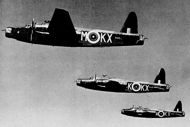
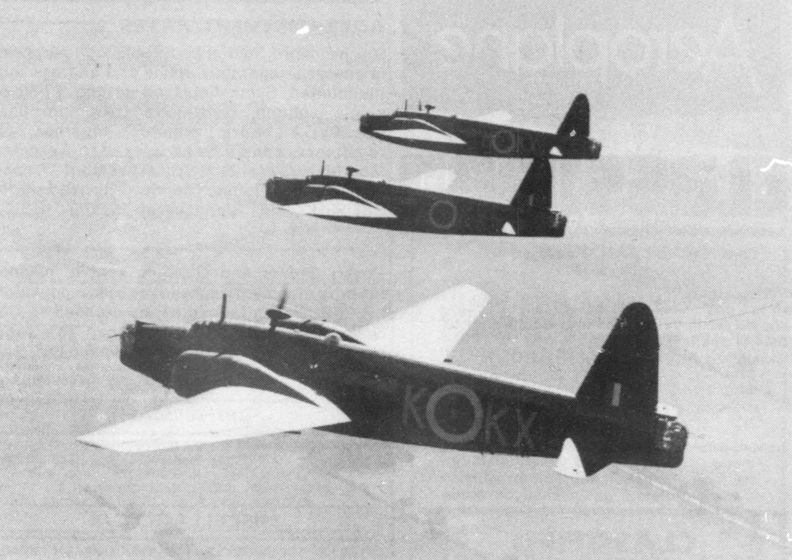
Три Wellington Mk IC из 311-й (чехословацкой) эскадрильи, которая в конце 1940 года базировалась в Хонингтоне. Взамен подфюзеляжных на них установлены бортовые пулеметы.
Three 311 Squadron Wimpeys over Norfolk; R1378 KX-K, T2561 KX-A and R1410 KX-M.
Три Wellington Mk IA из 37-й эскадрильи над Ливийской (Западной) пустыней (Северная Африка). Эскадрилья базировалась в Египте в течение декабря 1940 года и сыграла важную роль в захвате Тобрука 2 1 января 1941 года. Три часа ее самолеты "висели" над обороной итальянцев, маскируя своим шумом факт сосредоточения британцами своих танков и артиллерии.
Wellington P2521 'MA-V' of 161 Squadron was used for the first ASCENSION 'op' on April 8,1941.
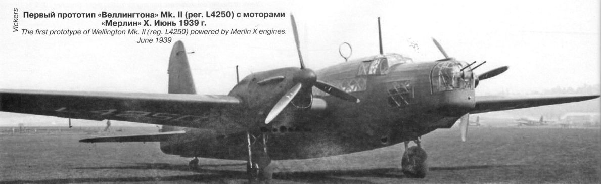
Mk.II
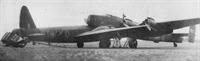
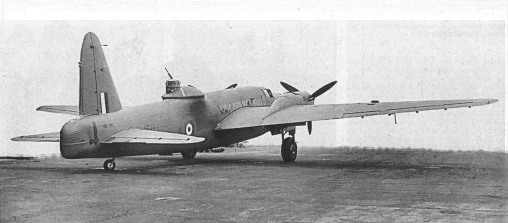
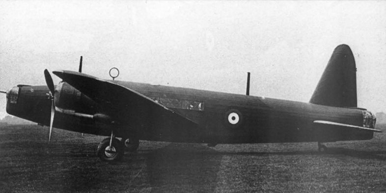
Первый прототип «Веллингтона» Mk.II (per. L4250) с моторами и «Мерлин» X. Июнь 1939 г.
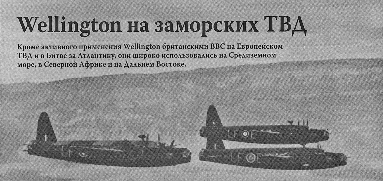
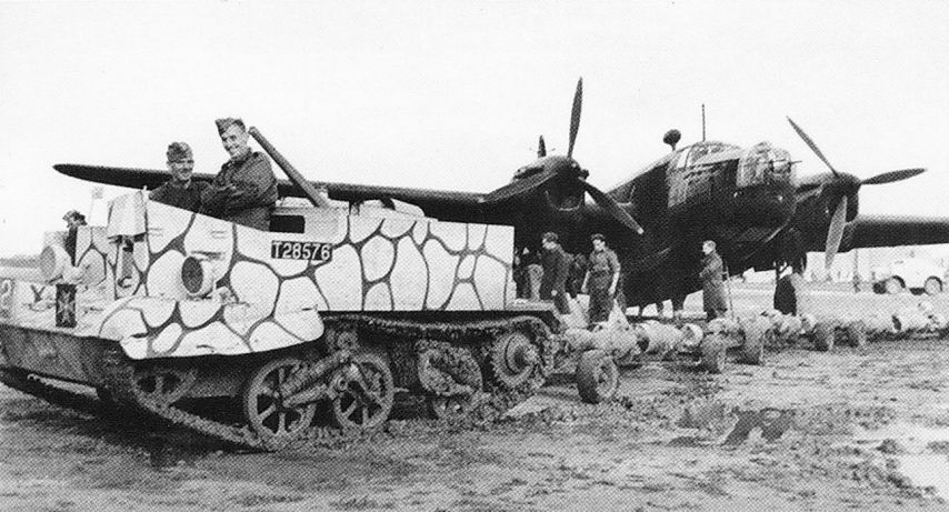
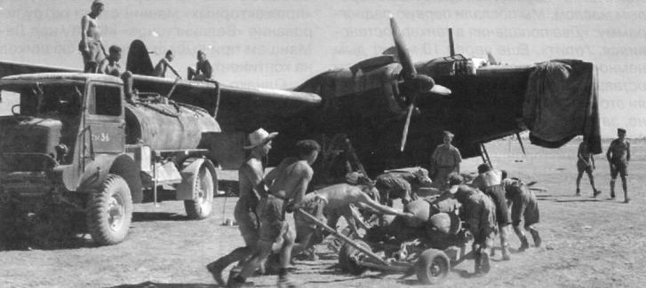
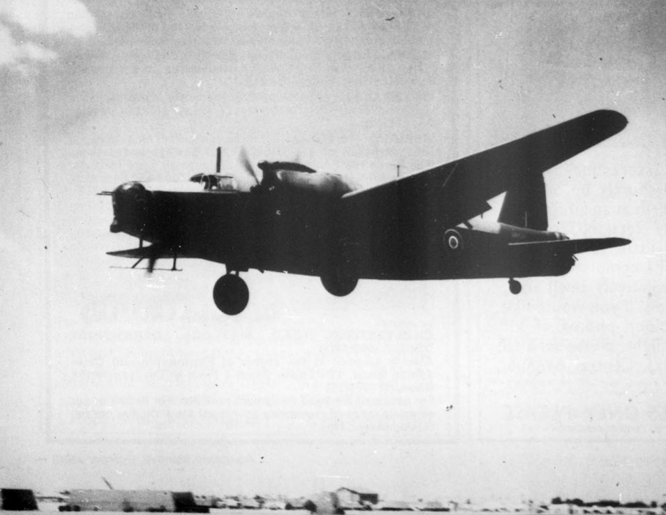
Британский армейский легкий бронетранспортер Bren Gun Carrier подвозит прицеп с авиабомбами к Wellington Mk II на аэродроме Лука (Мальта, 1942 год). Самолет стоял на вооружении 12 эскадрилий на Средиземноморском ТВД и принял участие в Греческой и Иракской кампаниях 1941 года, а также в течение всей кампании в Северной Африке.
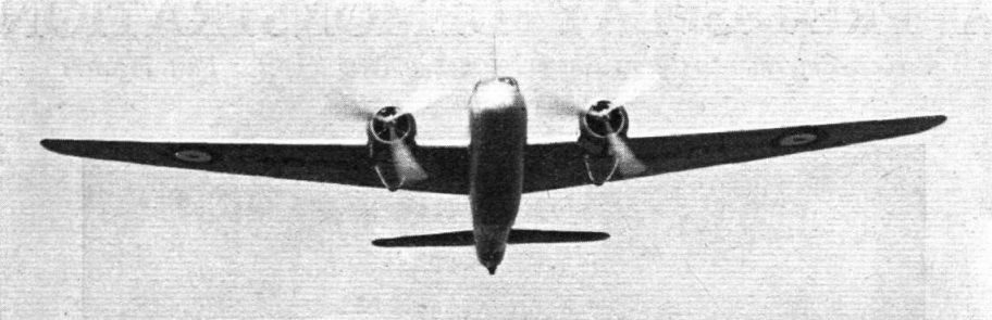
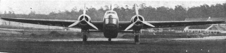
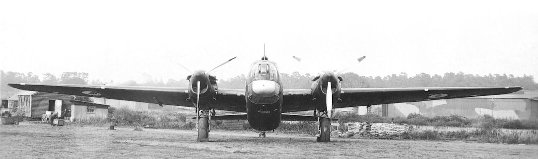
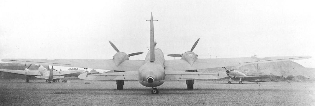
Head-on view of a Merlin-engined Mk.II.
WELLINGTON MARK II. Two Rolls-Royce Merlin engines, the mark number of which may not at the moment be disclosed, are fitted in this new Wellington. It is armed with five machine gun; and is believed to have a longer range than any bomber at present in service.
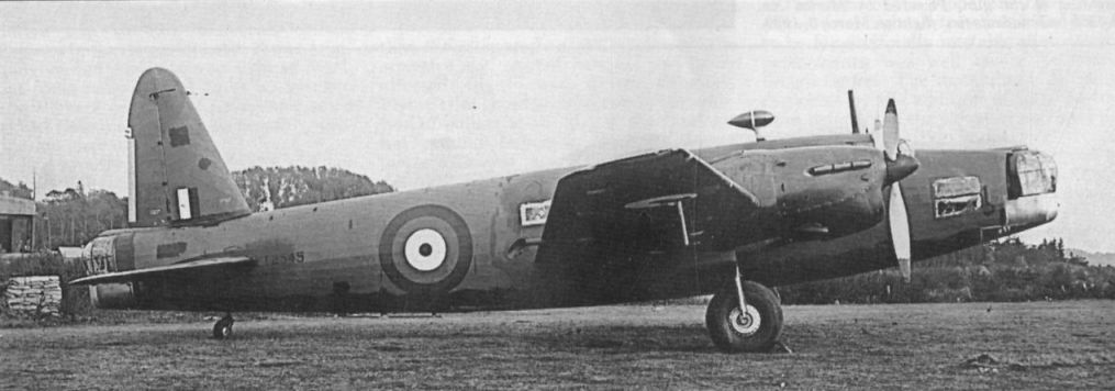
Wellington II T2545 was converted from a Mk IC.
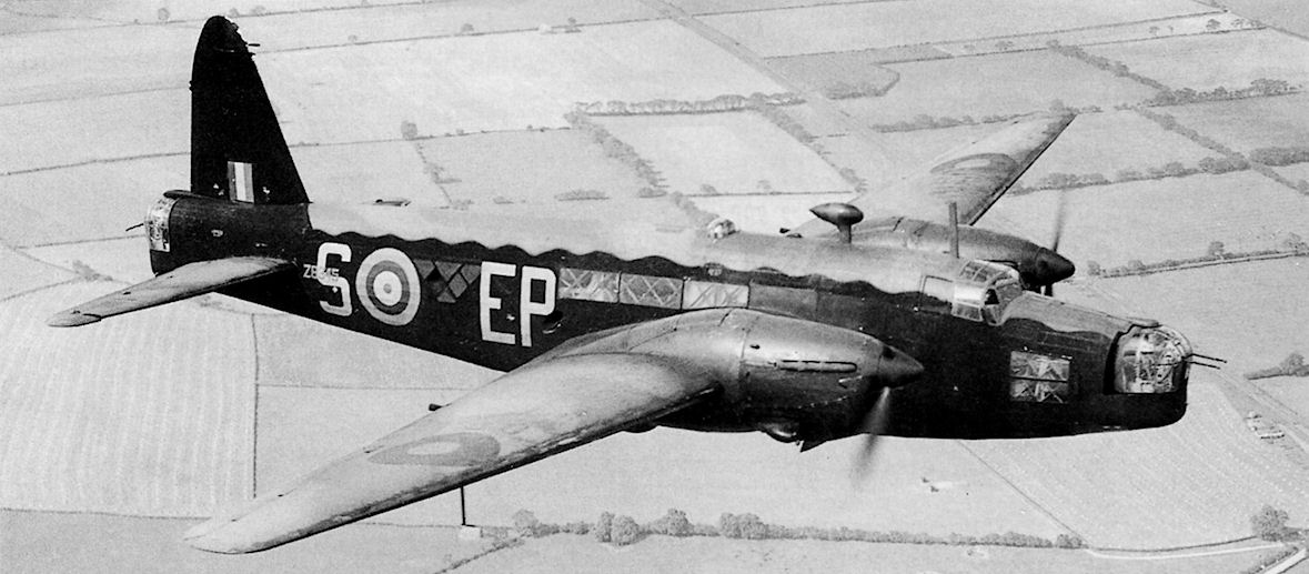
Mk.II W5442 in the colours of 214 Squadron, 1941. It later transferred to 12 Squadron and went missing on a raid to Essen on March 10, 1942.
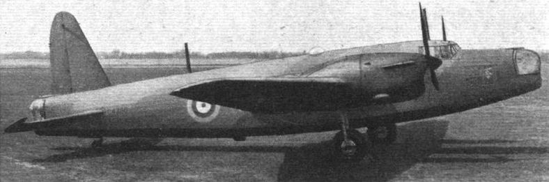
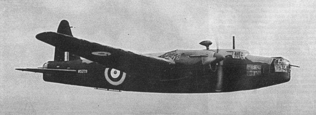
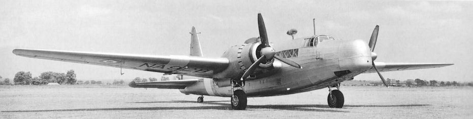
Wellington Mk II, W5379, powered by two Rolls-Royce Merlin X of 1,145 h.p. each. The prototype Mk II first flew on March 3, 1939.
W5379 was a Mk II, with Rolls-Royce Merlin engines and a Frazer-Nash turret in the nose.
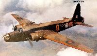
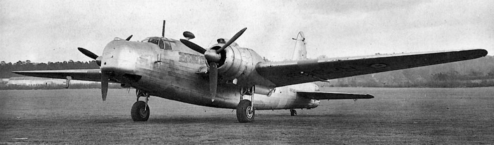
Двигатели Rolls-Royce Merlin X стояли на Wellington Mk II, a Bristol Hercules - на Wellington Mk III. Предприятие в Вейбридже построило 400 самолетов Wellington Mk II, поставки начаты в октябре 1940 года. Изображен самолет из 104-й эскадрильи до момента передислокации ее на Мальту.
Mk.II W5480 was issued initially to Boscombe Down for testing.
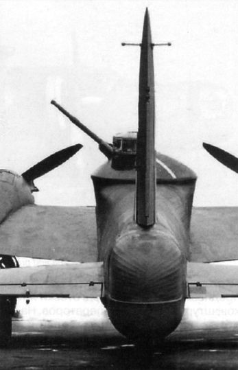
Mk II prototype L4250 photographed in June 1941, after installation of the 40mm Vickers ‘S’ cannon turret but before the single fin and rudder was exchanged for twin units.
40-мм пушка на «Веллингтоне» Mk. II (per. L4250)
«Веллингтон» (per. L4250) с 40-мм пушкой и новым двухкилевым оперением
The only company to flight test its 40mm cannon turret and predictor was Vickers, which modified Wellington II L4250 for the purpose, as seen here at Boscombe Down in January 1942. It originally flew with a single fin and rudder.
Wellington Mk II prototype L4250 after modification with twin fins and rudders to cure instability caused by the experimental Vickers 40mm cannon turret. The centre fuselage had to be rebuilt as a stressed-skin structure because the normal geodetic frame was too flexible to allow accurate sighting of the gun. Powered by Merlin Xs, L4250 had made its first flight on March 3, 1939.
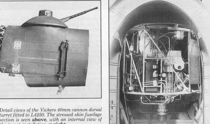
Detail views of the Vickers 40mm cannon dorsal turret fitted to L4250. The stressed-skin fuselage section is seen at left, with an internal view of the turret installation at right.
Mk.III
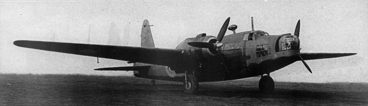
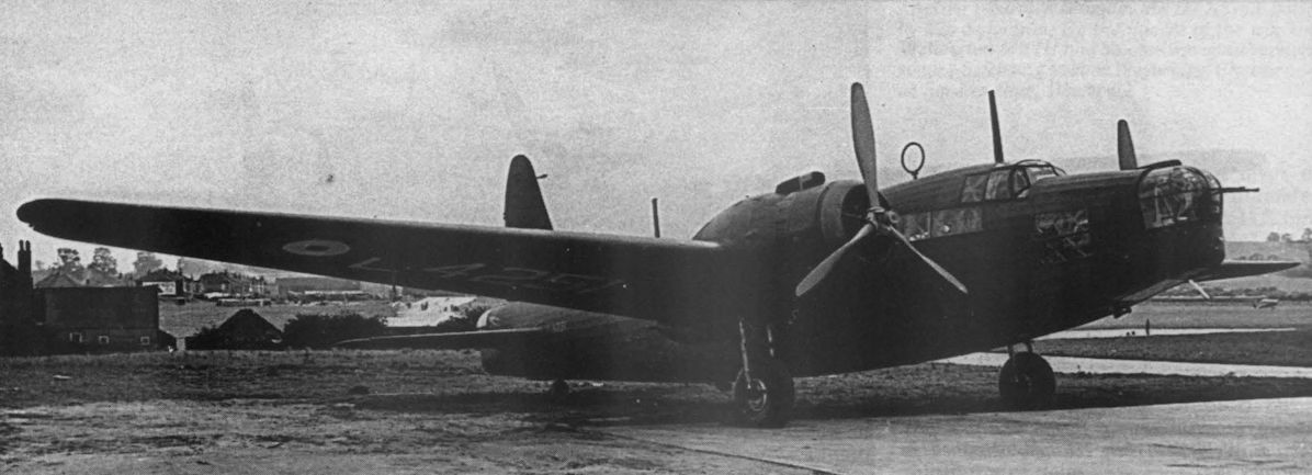
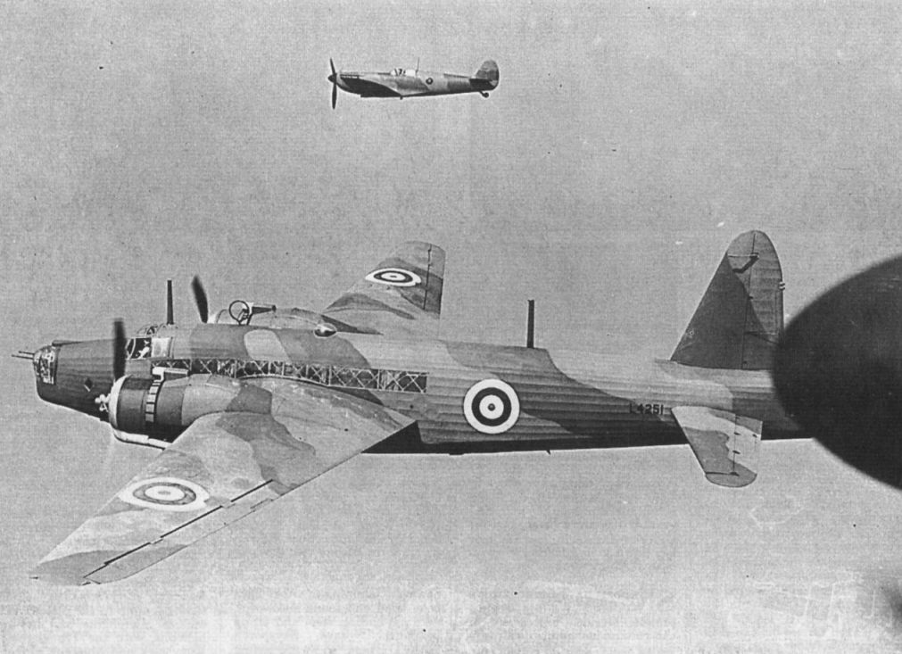
Another view of prototype Wellington III, L4251, first flown on May 19, 1939.
Первый прототип «Веллингтона» Mk.III (per. P9238) с двигателями «Геркулес». Май 1939 г.
Mk.I L4251 was converted to become the Hercules-engined Type 299 Mk.III prototype.
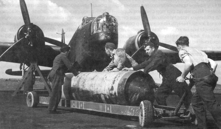
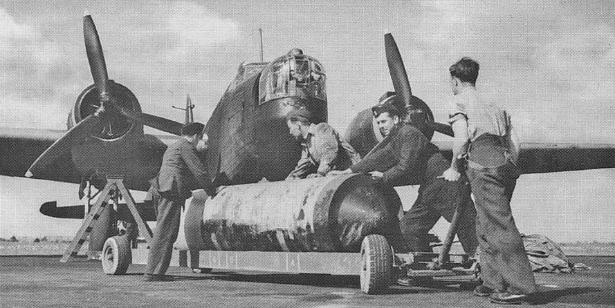
Подготовка 4000-фунтовой бомбы к загрузке в «Веллингтон» Mk.III
Специалисты по вооружению подвешивают 1814-кг авиабомбу "blockbuster" на Wellington Mk III. Первым из британцев во время налета 1 апреля 1941 года на Эмден ее сбросил Wellington Mk IC из 149-й эскадрильи.
Another view of P9238, the first production Wellington Mk III, photographed in February 1941.
The prototype Wellington Mk III, L4251, fitted with two Hercules HE ISM radial engines.
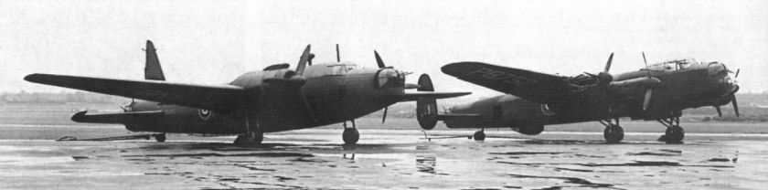
Wellington Mk III BK563 and Lancaster MK I PB752 fitted with experimental Dunlop tyres at Elmdon in 1946. Both aircraft retain their defensive armament. BK563 replaced Wellington BK187, which was damaged while taxying over boggy ground.
Wellington Mk III P9238, generally regarded as the first production Mk III, was first flown in January 1941.
The Vickers Wellington entered RAF service in October 1938 and, although designed as a day bomber, formed the backbone of RAF Bomber Command’s night raids during the early days of the war.
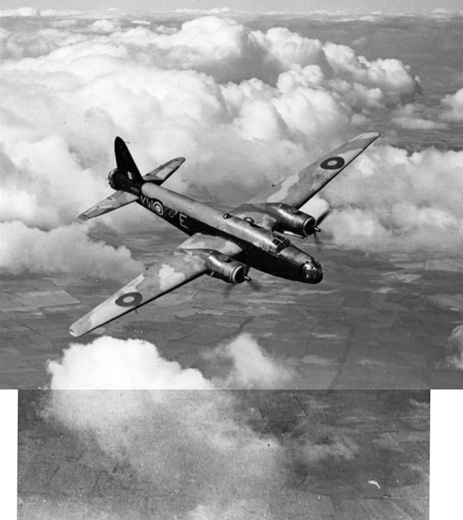
Vickers Wellington Mk III X3763 of 425 Squadron. On April 15, 1943 it was reported missing following an RAF raid on Stuttgart, Germany.
Воздухозаборники карбюраторов смонтированы на верхних поверхностях мотогондол, Wellington Mk III оснащался двумя моторами Bristol Hercules XI.
Squires Gate-built Vickers Wellington III X3763 of No 425 Sqn RCAF gambols above the clouds in early 1942. The unit was one of the “Article XV” squadrons established in 1941 to be operated by Dominion aircrews as part of Bomber Command’s expansion. This aircraft went missing on a raid on Stuttgart on April 15, 1943.
By the middle of the war the Wellington Mk III had become the main version, some 1,519 being built at Weybridge, Chester and at Squires Gate, Blackpool.
До появления четырехмоторных тяжелых бомбардировщиков самыми ценными у Командования бомбардировочной авиацией были двухмоторные самолеты, такие как этот Vickers Wellington из 419-й эскадрильи канадских ВВС. Харрис часто включал самолеты из учебных частей в состав сил для нанесения массированных авиаударов.
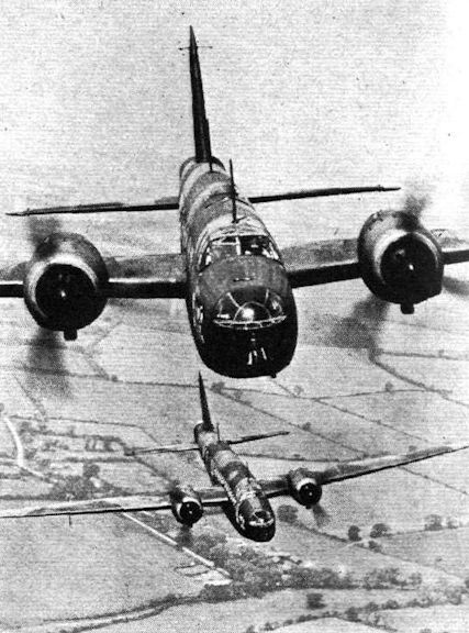
WELLINGTON MARK III: A prototype Vickers Wellington long-range bomber fitted with two Bristol Hercules 14-cylinder two-row sleeve-valve radials of at least 1,400 h.p. each. Flying alongside is one of the later Supermarine Spitfires fitted with Rolls-Royce Merlin III engine driving a De Havilland three-bladed variable-pitch airscrew.
Prototype Wellington III L4251, fitted with Bristol Hercules HE1SM engines, in company with a Spitfire.
Сброс «прыгающей» бомбы Уоллеса с бомбардировщика Виккерс «Веллингтон»
Mk.IV
Первый прототип «Веллингтона» B Mk. IV
View of the prototype Wellington Mk IV, R1220, lost in a crash at Addlestone, near the Vickers Weybridge works. R1220 was powered by two R-1830 Double Wasp radial engines.
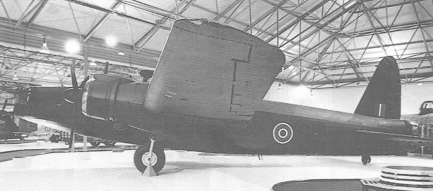
Mk.X
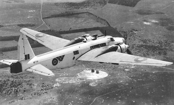
The Wickers-Armstrong Wellington X Heavy Bomber (two Bristol Hercules XVI engines).
The Vickers Wellington Mk X was the ultimate bomber variant of the type, built at Vickers’ Chester and Blackpool factories. The Mk X entered RAF service in 1943, by which time the type’s career as a frontline bomber was drawing to a close, Bomber Command’s four-engined heavies having taken over the primary bombing role.
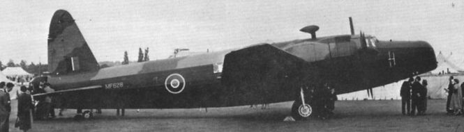
The world’s ‘other’ Wellington, T.10 MF628, displayed at the RAF Museum, Hendon.
Preparing an OTU Wellington for ‘work’, 1940-1941.
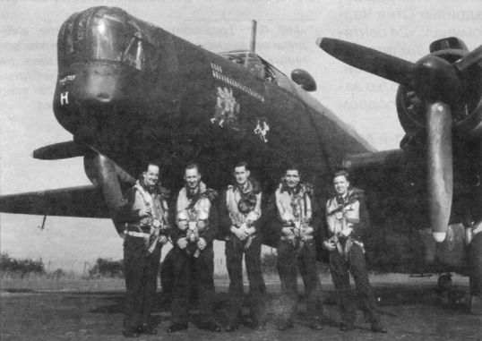
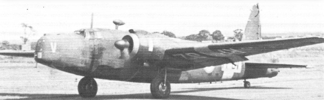
«Веллингтон» Mk. X из 420-й канадской АЭ. Северная Африка, лето 1943 г.
Экипаж 466-й АЭ возле «Веллингтона» Mk. X. Леконфилд, лето 1943 г.
"Веллингтон" X с моторами "Геркулес" VI
Подготовка к вылету «Веллингтона» Mk. X из 205-й АЭ. Италия, сентябрь 1943 г.
Vickers Wellington X MF628.
The Mk X saw the rebirth of the Wellington. Pre-delivery pose of Hawarden-built LP700 which entered service with 303 Ferry Training Unit at Talbenny which later became 3 Overseas Aircraft Delivery Unit. LP700 was struck off charge in May 1945 in the Mediterranean theatre.
Fine pre-delivery image of Hawarden-built Mk.X LP700.
Wellington Mk X MP841 lands at El Kabrit, Egypt on February 18, 1943. Note radar aerials under the wings.
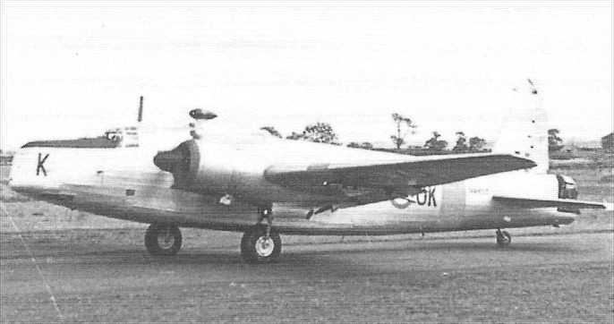
Vickers Wellington Mk 10 NC565 at RAF Fayid in early 1947. The last of the bomber variant post-war Mk Xs were reconditioned for use as crew trainers; known as the T.10, it had a faired nose and no turret.
T.10 MF628 carrying the codes ‘FFK-B’ of 1 Air Navigation School, Hullavington.
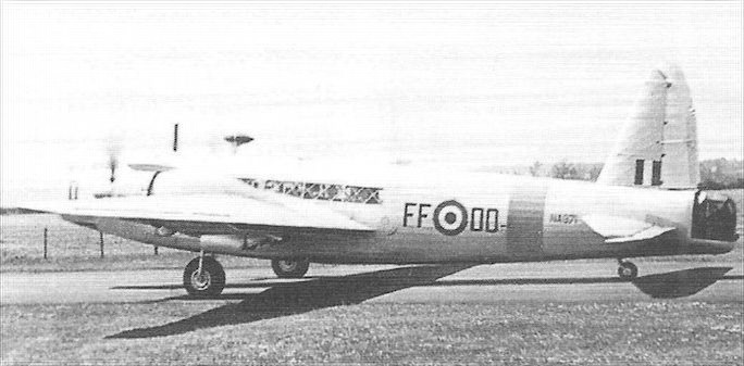
T.10 NA928 in full guise, complete with ‘Trainer’ bands. Also Hawarden-built, it saw no service as a B.X and was stored until converted by Boulton Paul. In its new role it served with the Empire Central Flying School at Hullavington, the Handling Squadron at Boscombe Down and finally 1 Air Navigation School, also at Hullavington. One of the last ‘Wimpeys’ flying with the RAF, it was sold as scrap on December 30, 1953. Stored Lincolns in the right background.
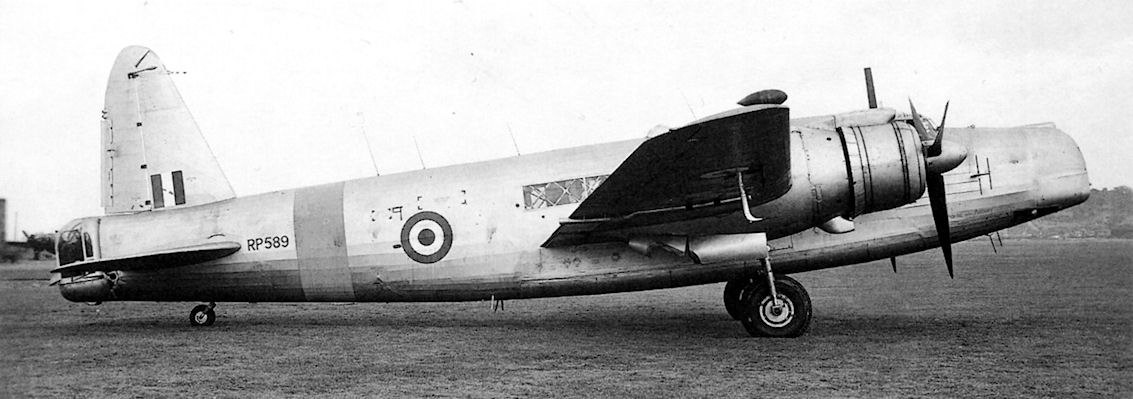
Оснащенный двигателями Hercules, T.Mk 10 RP589 был построен в октябре 1945 года и стал предпоследним в истории Wellington. Всего же за 8 лет были выпущены 11460 самолетов.
The November/December 1996 issue dealt briefly with the Wellington T.10 ‘stop-gap’ navigation trainer. The type served widely with 2 Air Navigation School using large numbers at Middleton St George and, from 1950, at Thorney Island. RP402 ‘FFOV’ shows the initial Bomber Command camouflage, but with yellow ‘Trainer Bands’ on the wings and mid-fuselage. Note that the Flying Training Command four-letter code is also against a yellow background.
NA853 ‘FFOK’ exhibits what are thought to be black spinners - or was there colour-coding for the three flights of 2 ANS?
NA971 ‘FFOO’ illustrates the definitive silver/yellow scheme. It did not last long after the move to Thorney Island, being struck off charge in October 1951.
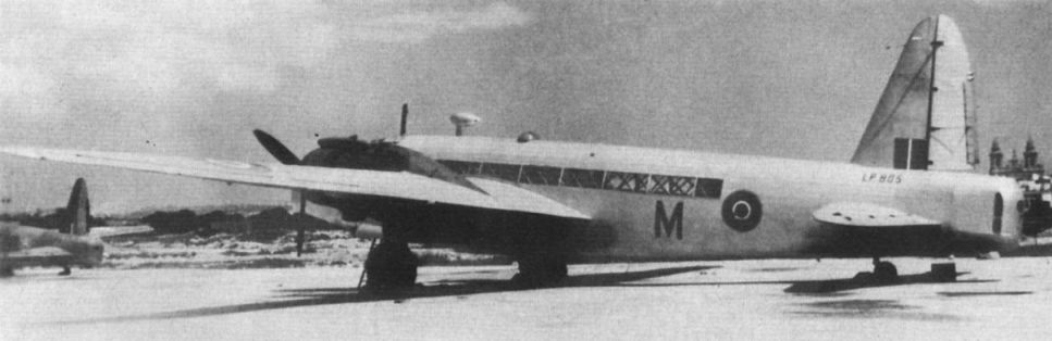
The Wellington T.Mk X was the trainer version of the B.Mk X, having its front and rear turrets removed and faired over. Wellington Mk X MF628, preserved at the RAF Museum, Hendon, is the Sole survivor of 11,461 Wellingtons built. Our photographs show LP805 before its last take-off.
T.10 MF628 at the ‘Fifty Years of Flying’ display at Hatfield on June 14, 1953. Note that the fuel jettison pipes on the underside of the wings have been removed.
Wellington T.Mk 10 в послевоенном серебристом камуфляже с желтой полосой учебной машины, 1945 год. Учебно-тренировочный Mk 10 был последней модификацией Wellington, поступившей на вооружение британских ВВС. Среди его получателей были штурманские школы и 201-я школа повышенной летной подготовки. Самолет был отправлен в отставку в 1952 году, одна машина была сохранена в музее ВВС.
T.10 RP589 pictured in January 1949, note the glazed rear turret. This aircraft was built at Blackpool in mid-1945 and flew with Vickers at intervals, but also (in chronological order) with the Telecommunications Flying Unit at Defford, the RAE and the A&AEE. It was struck off charge in March 1951.
Последними Wellington в британских ВВС были T.Mk 10, использовавшиеся после войны для подготовки штурманов. Все они были переоборудованы компанией "Boulton Paul" из бомбардировщиков Mk X. MF628 принадлежал 6-й эскадрилье, а с 1949 года находится в Музее Королевских ВВС Великобритании.
Mk.XIII
Wellington Mk XIII HX516 retracts its undercarriage taking-off from El Kabrit, Egypt, on February 19, 1943.
Mk.XVI
«Веллингтон» Mk.XIV с неуправляемыми ракетами под крылом
The Wellington evolved in shape and role throughout the war. Mk.XIV MP714 with a special rocket projectile fit during A&AEE acceptance trials, July 1943.
Another view of rocket-equipped Mk.XIV MP714. Anyone care to comment on the installation on the ground immediately below?
Mk.XVIII
Squires Gate-built Mk.X NC928 following conversion to Mk.XVIII.
NC928 - оснащенный двигателями Hercules и РЛС AI самолет Wellington Mk XVIII для подготовки операторов РЛС. Радар размещен под обтекателем в носовой части, а самолет окрашен в стандартный камуфляж Бомбардировочного командования.
Mk.XIX
Учебный «Веллингтон» T Mk.XIX, переделанный из Mk.X (per. MP530)
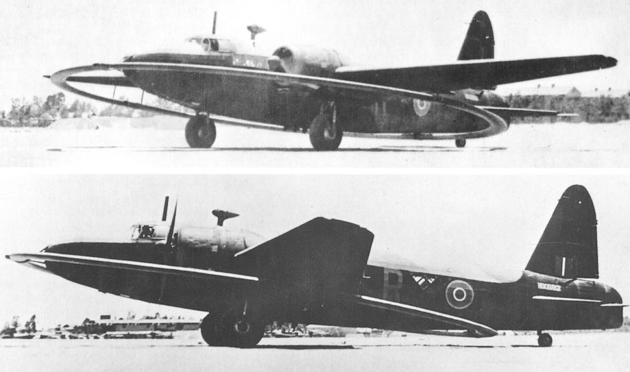
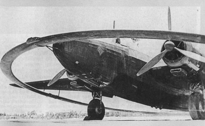
DWI
Этот Wellington DWI переоборудован из бомбардировщика Mk IC и служил на Ближнем Востоке, где применялся при тралении участков акватории Средиземного моря и Суэцкого канала.
Two views of DWI conversion HX682.
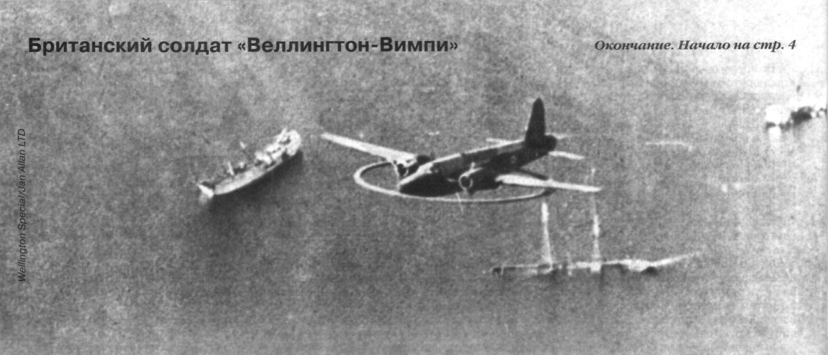
The Wellington DWI used a magnetic coil weighing some 2 1/2 tons for seeking out German magnetic mines.
Vickers Wellington with a degaussing ring.
"Противоминный" Wellington DWI Mk.I оснащался большим дюралевым кругом, по которому пропускался высоковольтный ток. Возникающее магнитное поле должно было подрывать немецкие магнитные мины, которые выставляли в базах, портах и гаванях. Круг имел диаметр 14,6 м и весил 2250 кг, не оказывая особого влияния на летные характеристики самолета, исключая увеличение взлетной дистанции. Такие Wellington получили прозвище "Flying Magnet" или "Wedding Ring Wimpey".
Vickers Wellington carrying a degaussing ring (mid-November 1939).
G. S. W. Challen’s photograph of a DWI Wellington at Manston in 1939
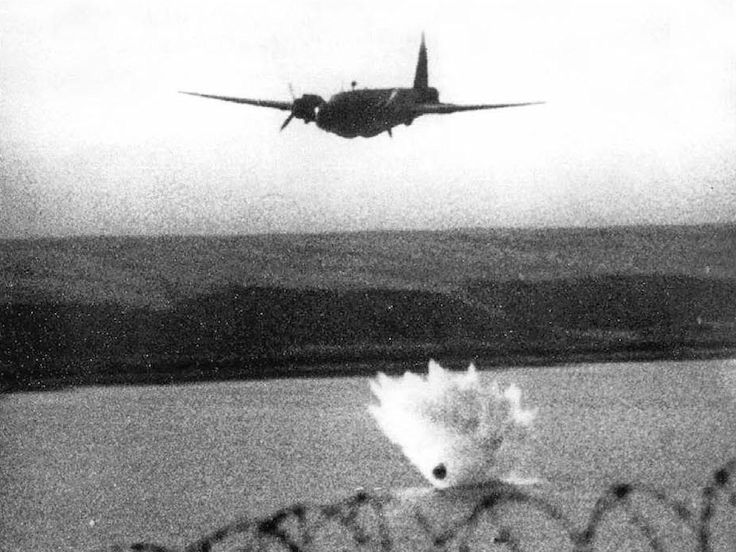
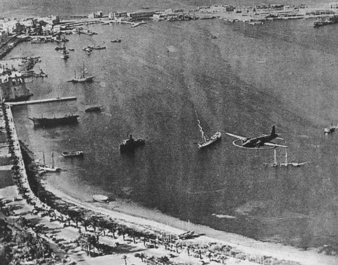
A Wellington DWI flying over Tripoli harbour in Libya. The ring had a diameter of 48ft.
Test-bed
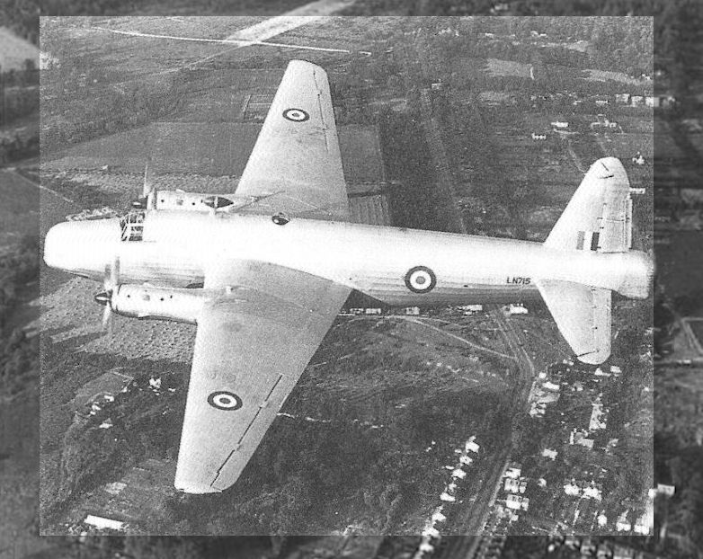
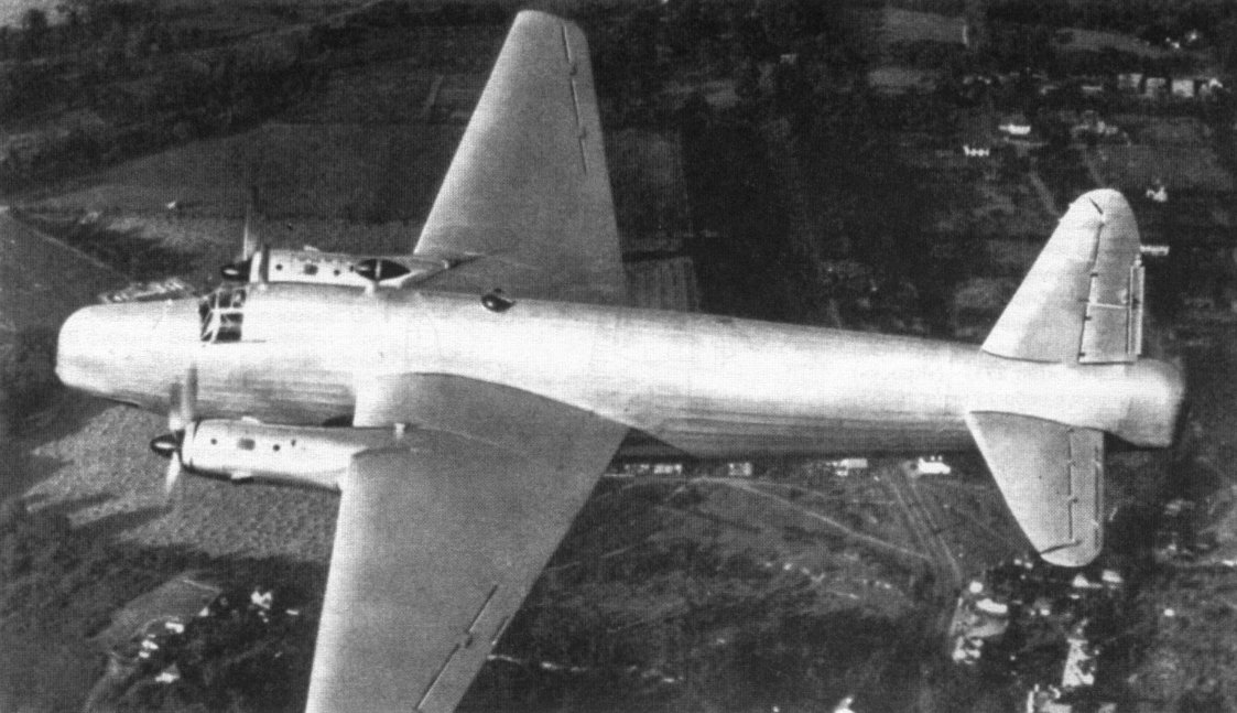
Летающая лаборатория для испытаний двигателей Роллс-Ройс «Дарт»
Wellington T.10 LN715 was fitted with two Rolls-Royce Dart turboprop engines for trials associated with the Viscount.
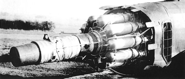
Летающая лаборатория для испытаний реактивного двигателя Уиттл W2
A Power Jets W2/700 engine installed in the tail of Mk.II W5518/G, with the engine covers removed.
A Welland test-bed very likely at Boscombe Down. In the background to the right is the 'mystery' Battle test-bed illustrated in AE126.
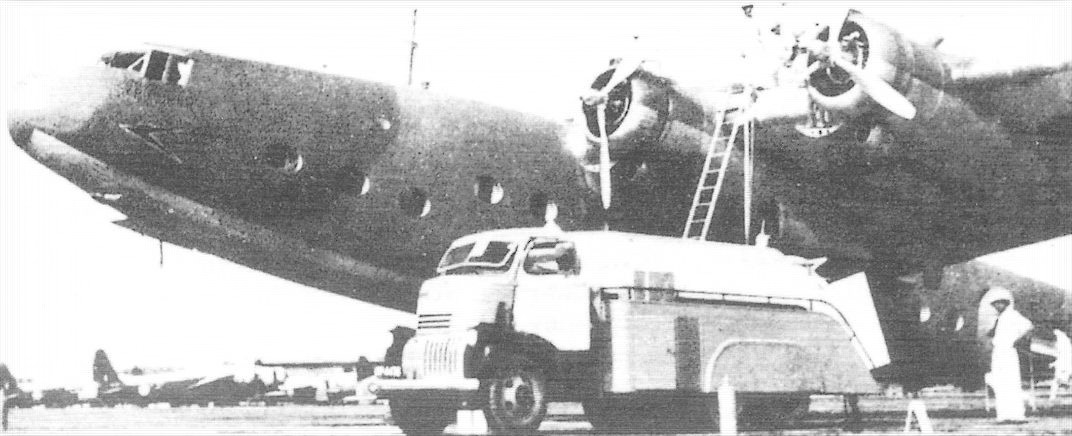
AW Ensign II G-ADSV Explorer of BOAC at Takoradi, circa 1943. Wellingtons in the background and a most impressive refuelling truck in the foreground.
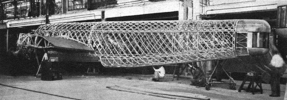
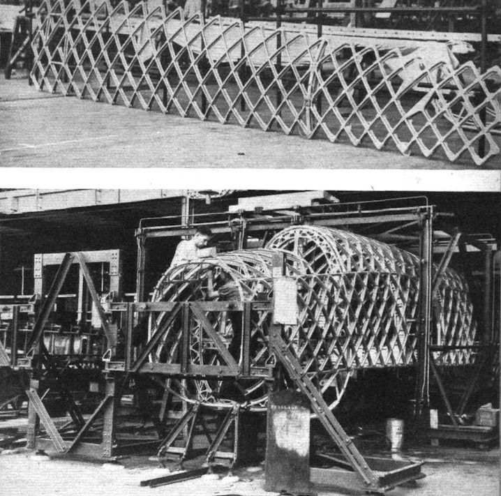
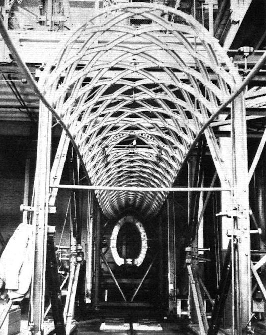
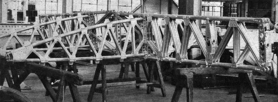
The geodetic airframe of the B.9/32 during construction.
A fuselage with its primary structure complete and the wing centre-section attached.
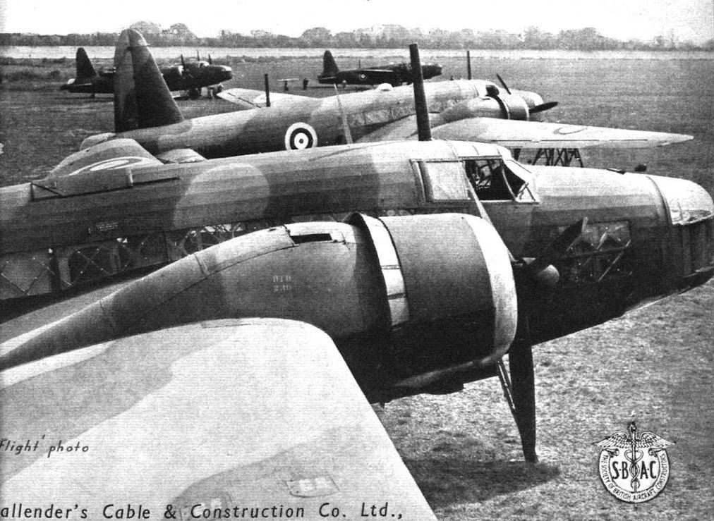
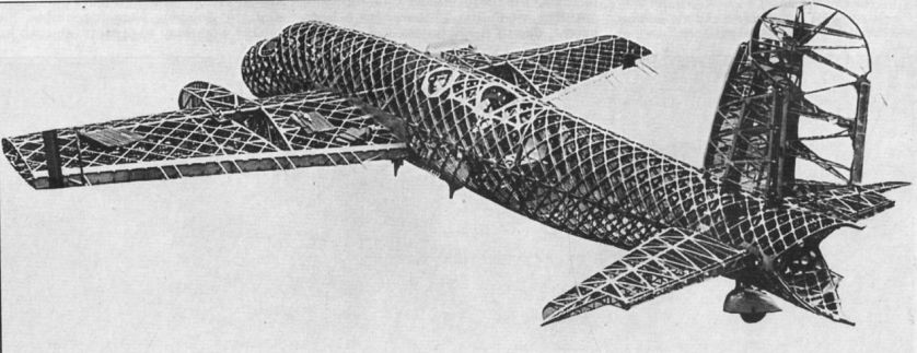
The photograph was taken at Brooklands in July 1939. The basketweave geodetic construction had already been used in the Wellesley and it allowed the Wellington, seen here, to absorb a great deal of punishment.
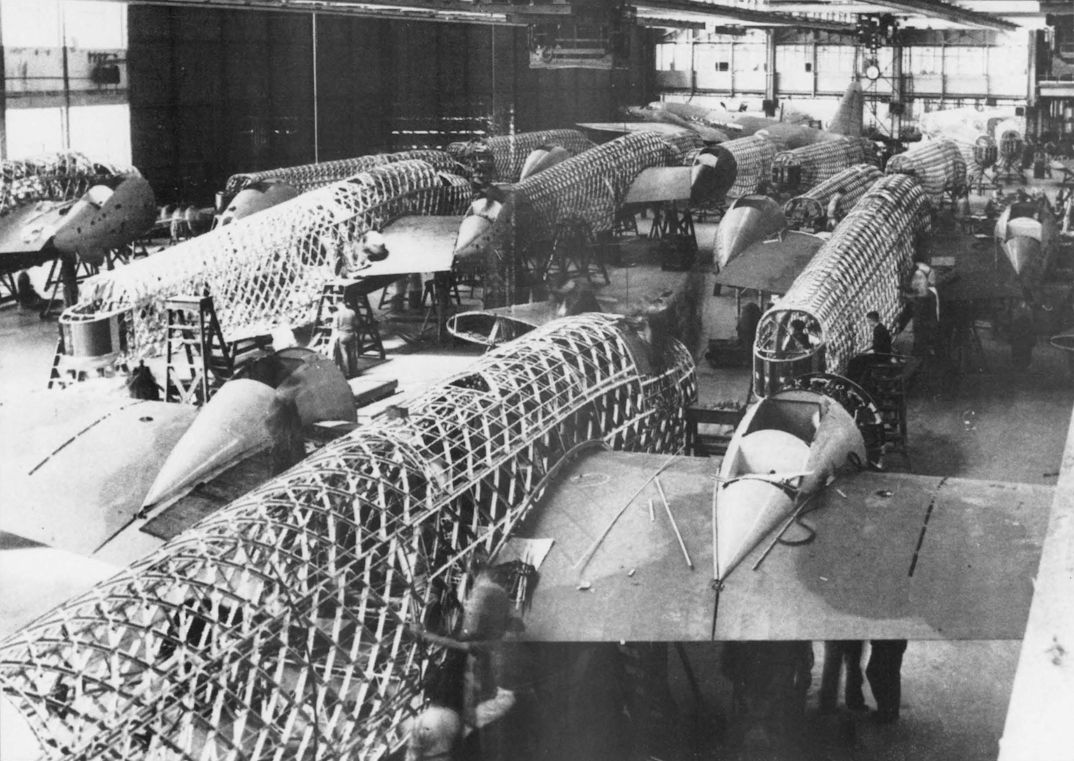
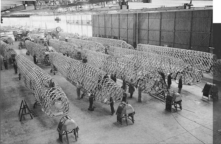
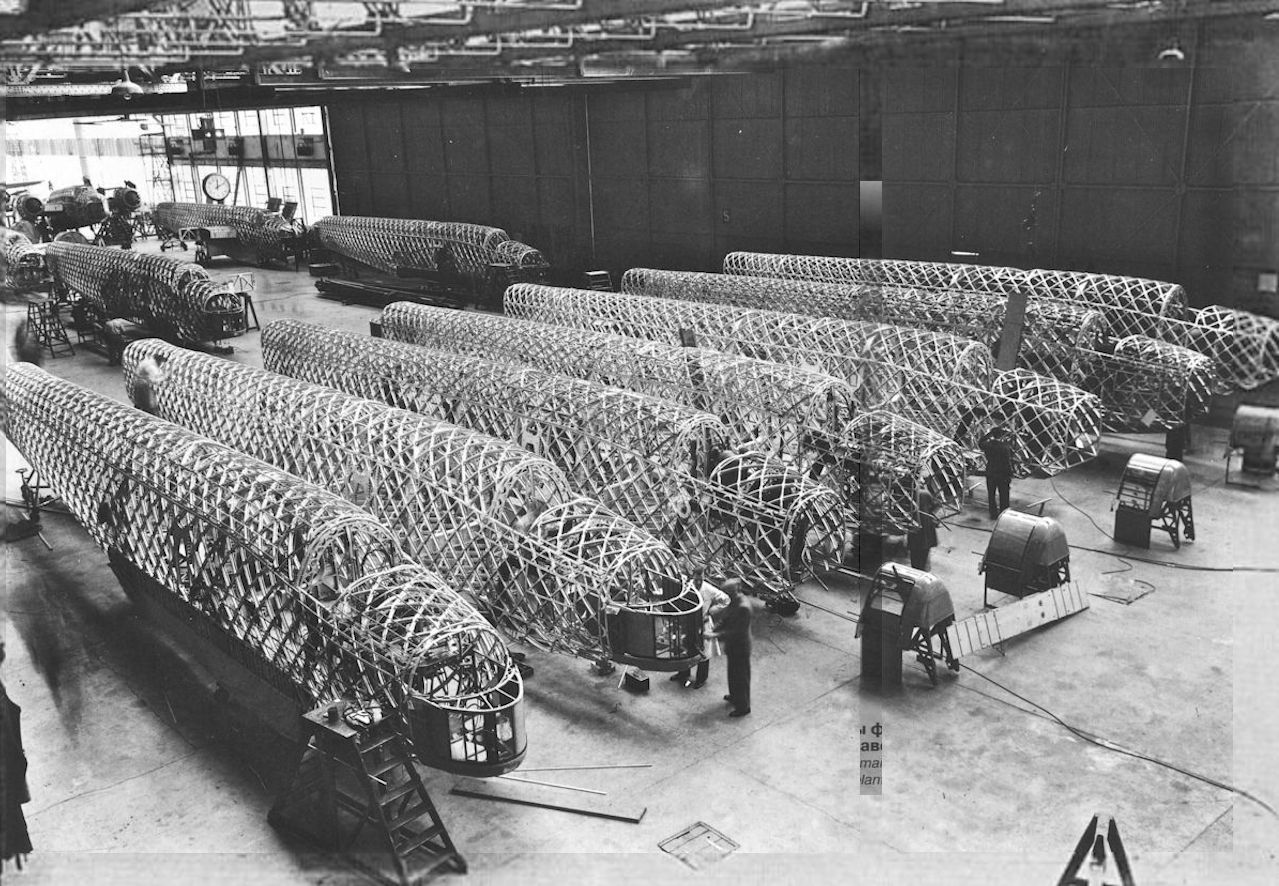
Скоро эти конструкции превратятся в бомбардировщики Wellington Mk I, предназначенные для Бомбардировочного командования (завод в Вейбридже, 1939 год). На фотографии хорошо видна геодезическая конструкция фюзеляжей.
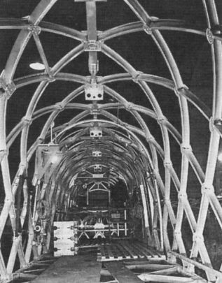
Vickers Wellington fuselages under construction.
Wellington I fuselages in the erecting shop at Weybridge in 1939, with front turrets designed by Wallis nearing completion.
Каркасы фюзеляжей "Веллингтонов" Mk.I на авиазаводе в Бруклендсе. Начало 1939г.
The fuselage of the B.9/32 is almost complete before it is turned over for the bottom section to be attached.
One of the complete side panels of a fuselage, ready to be put in the jig for attachment to the top and bottom panels. Below is seen a fuselage nearing completion in its assembly jig.
After removal from the jig the fuselage is placed on trestles to have the equipment installed. The two pictures show two stages in this process
Nearly completed fuselage reveals the basic geodetic with no bulkheads.
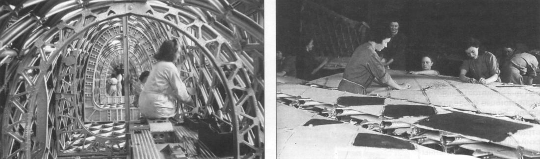
В условиях войны широко применялся женский труд. Слева - сборка фюзеляжа «Веллингтона», справа - обтяжка крыла
Top panel of rear fuselage portion in its jig.
Fuselage top panel temporarily supported in jig in readiness for attachment to fuselage sides. In the background can be seen one of the tailplane frames
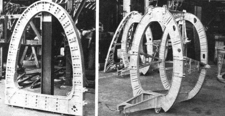
A main spar fuselage frame. This serves as one of the key foundations for the whole fuselage assembly. On the right is the double frame which carries the tailplane and tail wheel. This is assembled as a complete unit.
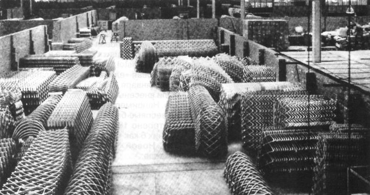
Элементы конструкции «Веллингтона», поступившие с заводов-смежников
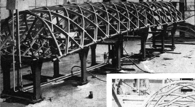
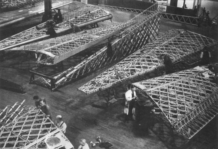
Сборка крыла «геодезической» конструкции
A port outer wing portion in the covering shop - the two-position centre-section attachments can be seen.
Inner main plane spar with wing root ribs. The spar booms are joined on the centre line of the fuselage.
Panels of inner wing portion in their jigs.
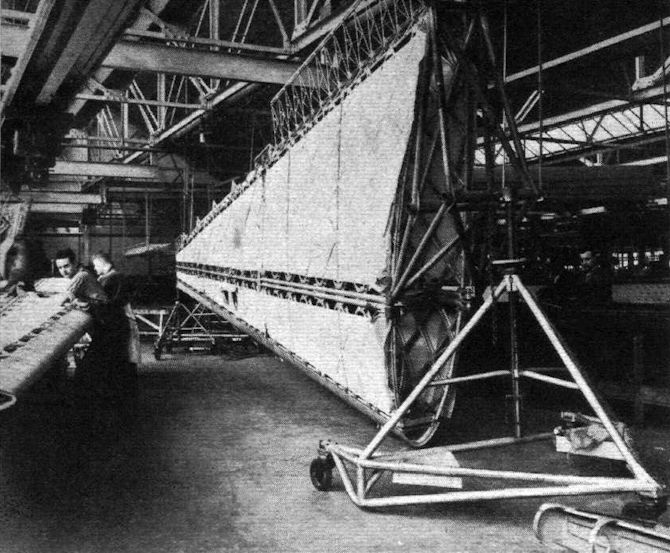
The use of jacks and trunnion mountings facilitates moving the wings about and turning them over while the fabric is being attached.
A scene in the wing-covering shops, where female labour is used exclusively.
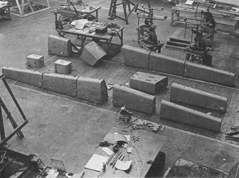
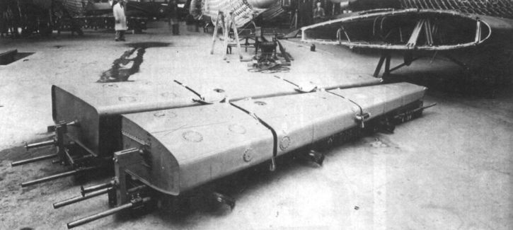
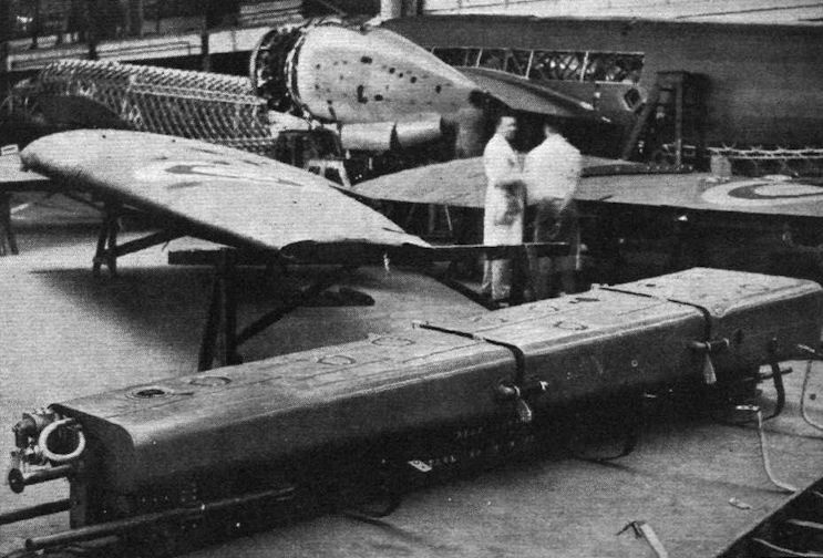
The B.9/32's wing fuel tanks awaiting installation.
Топливные баки перед установкой в левое полукрыло
The Wellington, with its extremely long range, has comprehensive tankage arrangements. The tanks (riveted by the De Bergue system) taper in conformity with the wing.
Details
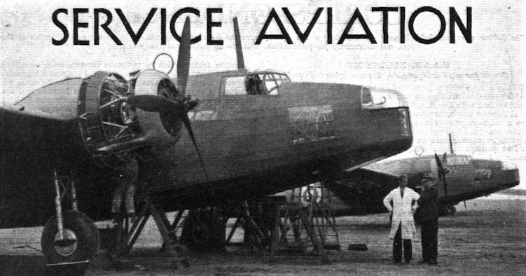
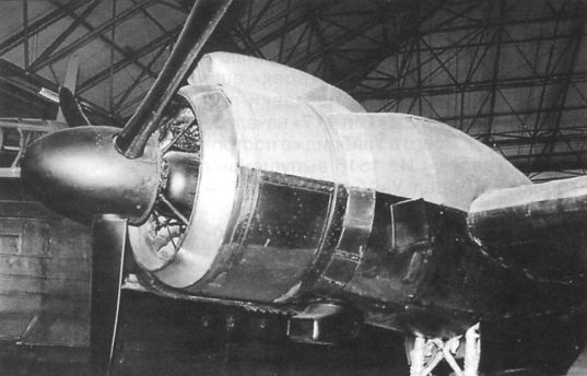
Обслуживание двигателей «Пегасус» XVIII
Мотогондола двигателя «Геркулес» XI
A close-up of a Rolls-Royce Merlin X engine in a Wellington II. The Merlin X was rated at 1,145 h.p.
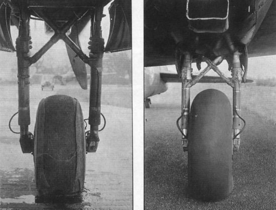
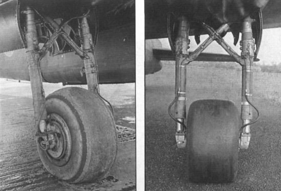
Левая основная опора шасси
The two photographs show the initial Compacta experimental aero tyre at left, with a normal-sized wheel and tyre assembly at right. Successive very hard braking almost tore the Compacta to pieces. The aircraft used for these experiments was Wellington Mk III BK563.
Left, a production tyre, used for intensive flight development, fitted to Wellington BK563. Right, a Compacta experimental aero tyre is seen in its final development stage.
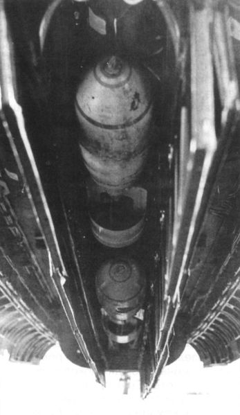
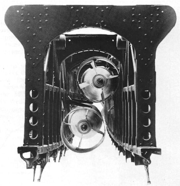
Авиабомбы в центральной секции бомбоотсека
The centre cell of the bomb hay of a Wellington showing two 250 lb bombs.
Airmen pose whilst 'gunning up' a Wellington.
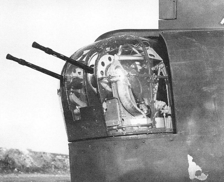
The Frazer-Nash hydraulic front turret of a Mk II Wellington, showing the twin 0-303in Browning machine guns.
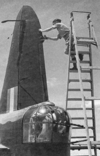
The twin-Browning tail turret of a Wellington II. The turrets used a 300 lb/in hydraulic supply.
Турели Vickers, стоявшие вначале на Wellington Mk I, на Mk IA были уже заменены на турели производства "Nash and Thompson". Носовая и хвостовая турели имели по два 7,7-мм пулемета Browning (на снимке). Кроме того, имелась выдвижная подфюзеляжная турель с одним пулеметом, которую позже заменили на бортовые пулеметы.
Четырехпулеметная турель FN4A


 Wikipedia