
 Wiki
Wiki Flight, December 1934
A VARIABLE-INCIDENCE GYROPLANE
Preliminary Details of the Kay Gyroplane: Incidence of the Blades Variable at the Will of the Pilot
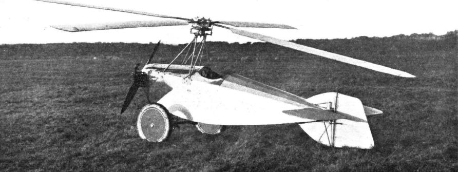
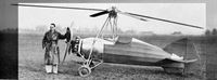
IN the wilds of Scotland, Mr. David Kay and his friend, Mr. John Grieve, have for some years been experimenting with a rotary-winged aircraft incorporating an ingenious system for varying the incidence of the blades. A prototype was built at Perth and tested with quite a considerable amount of flying, not only by the inventor, but also by an Air Ministry official. The results obtained were so promising, and the interest shown in the machine so great, that it was decided to produce some improved machines, and the first of these is now practically ready for test flights at Southampton Airport.
Structurally, the fuselage is a fairly straightforward welded steel-tube body with a conventional widespread undercarriage and an engine mounting in the front carrying a Pobjoy "R" engine working a four-bladed airscrew. The pylon carrying the rotor head above the fuselage is of steel tubes, and is particularly rigid, as, before taking off, the rotor has to be speeded-up to about 400 r.p.m.
This speeding-up is done by a straightforward power transmission layout from the rear of the engine via a Ferodo-faced cone clutch and bevel gearing to a shaft terminating in a vertically toothed pinion driving on the internal teeth of a ring encircling the head. This pinion is mounted eccentrically, so that it is thrown out of gear when the head over-runs the drive. In this position the head is free to rotate and the autogyratory process starts.
Four blades of fairly normal construction with tapered-gauge steel tube spars, wooden ribs and plywood covering are connected by links to the rotating portion of the head. This portion is mounted on a transverse "Z" crank, the oscillation of which produces a lateral rocking motion of the head, and therefore of the complete rotor system. This motion is not at right angles to the centre line of the machine, so that a small pitching moment is involved, and this moment serves to counteract any tendency to climb or dive during turns.
A “spectacle” form of control wheel operates this "Z" crank for lateral control purposes. Fore and aft control is secured by a pull-and-push motion of this wheel, operating normal elevators, while direction is controlled by pedals and a rudder. Fore-and-aft trim is secured by a wheel-operated screw which gives a permanent tilt to the head.
The incidence of the four blades is varied by mounting each link which secures the blade itself to the head on individual "Z" cranks. A screwed shaft runs right up through the head, operating small cranks and levers to each blade link for the rotation of these "Z" cranks. The hand control of this variable-incidence system has various safety connections which ensures that the rotor can only be run up with the blades set in the position of no lift.
Briefly, the operation of the Kay Gyroplane is as follows: The rotor is run up to about 400 r.p.m. with the blades set at negative incidence, and the drive mechanism is then released. At the same time the incidence of the blades is increased to a positive degree, when it is found that the momentum of the blades, which promptly slow down to about 230 r.p.m., serves to lift the machine from the ground. Releasing the drive, of course, transfers the whole output of the engine to the tractor airscrew, and as the machine moves forward the autogyration continues, resulting in a steady climb according to the amount of control used.
A great asset of this system will probably be found when high-speed tests are made, as the accentuated coning angle which the blades take up when their incidence is high is naturally a serious drag-producing factor. With the Kay Gyroplane the incidence can be reduced at operational height so that the coning angle is reduced and therefore the drag, and the speed is increased. Thus it would seem that this machine embodies the same effects as a slotted, flapped, variable-area and variable-incidence fixed-wing aircraft. A further point of value in the variable incidence is the braking effect which can be secured at the moment of landing by an increase in incidence, so that extremely gentle landings can be made. Finally, setting the incidence at a negative value immediately on landing precludes any possibility of the machine blowing over in gusty winds.
There are, of course, many other points of great interest in this machine, with which we hope to deal after flying trials have been made.
- Flight, December 1934
A VARIABLE-INCIDENCE GYROPLANE
Фотографии

-

Flight 1933-11 / Flight
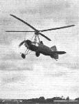
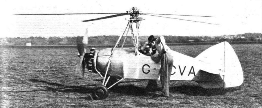
THE KAY GYROPLANE: The special feature of this machine is that the angle of incidence of the rotor blades can be altered by the pilot during flight. One of the directors of Kay Gyroplanes, Ltd., is Lt. Col. M. Ormonde Darby.
-
Air-Britain Archive 1992-02 / Extracts
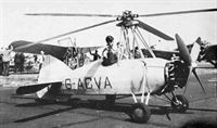
Регистрационный номер: G-ACVA [8] The Kay Single-seat Light Gyroplane (75 h.p. Pobjoy "R" engine).
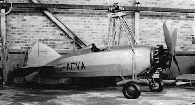
The Kay Gyroplane G-ACVA c/n 1002 assembled ready for flight but still in primer before final painting. The conventional rudder and elevators can be seen, also the additional ground clearance for the 4-blade wooden propeller provided by the Pobjoy reduction gear in raising the propshaft above the engine centre line.
Aeroplane 28 June 1946 *P.748 - A brief report on McDonald Aircraft Ltd of Balado Bridge. CFI is David Kay, who said his Gyroplane would shortly reappear. The company runs Loch Leven Aero Club with Cirrus & Pobjoy Swallows, Tiger Moths and an Autocrat. They are also disposing of large numbers of Barracudas, including the first one, P9976. They converted Hudsons and Lodestars for the Norwegians during the war, and are reconditioning Sidney Cotton's Lockheed 12 for sale.
28.6.46 p.748: The Kay Gyroplane was G-ACVA c/n 1002 which was flown at Perth up to 16.8.47 and now in storage for the Glasgow Museum of Transport.
28.6.46 p.748: More on the Kay Gyroplane, it was built at Eastleigh by Oddie, Bradbury & Cull who made rotor blades for the Cierva autogyros. It was taken by surface transport to Perth for its first flight which was followed by tests at Farnborough. Power was a 75hp Pobjoy R driving a 4-blade fixed pitch propeller, lateral control was by cyclic variation of main rotor pitch and G-ACVA had an orthodox rudder and conventional elevator system. C/n was 1002, no doubt due to the fact that there was an earlier unregistered Kay Gyroplane 1 in 1933, a smaller machine powered by a 2-cyl horizontally-opposed Blackburn engine. It flew successfully but after a crash was dropped in favour of the more powerful G-ACVA which first flew 18.2.35. -

Flight 1936-05 / Flight
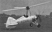
Регистрационный номер: G-ACVA [8] FURTHER DEVELOPMENT: The Kay gyroplane, which was originally described in Flight of December 27, 1934, is out again for experimental work in its new form. It will be remembered that this machine has a unique method of varying the incidence of the blades and has been undergoing tests at Farnborough.
-

Flight 1939-01 / Flight
Регистрационный номер: G-ACVA [8] A British light single-seater rotary-wing machine - the Kay gyroplane.
-
Air-Britain Archive 1981-03 / Impressment Review (7)
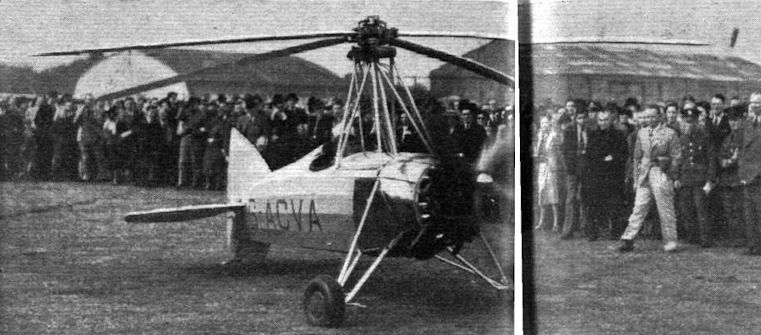
Регистрационный номер: G-ACVA [8] An opportunity to compare autogyros. G-ACVA was a Kay Gyroplane on show at Hendon in 1953
-
Flight 1938-05 / Flight
Регистрационный номер: G-ACVA [8] UP AND AWAY: An interesting little representative of the too-slowly-growing ranks of rotating-winged aircraft is the Kay gyroplane, which was demonstrated at the R.Ae.S. Garden Party. It has controllable-incidence rotor blades.
-
Aeroplane Monthly 1986-01 / 1986 UK Aircraft Collections and Museums Guide
Регистрационный номер: G-ACVA [8] The Kay Gyroplane, G-ACVA, has a four-bladed rotor with incidence control.
A pre-war shot of the Kay Gyroplane, now in the Glasgow Museum of Transport. -
Flight 1935-09 / Flight
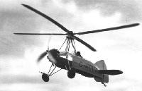
Регистрационный номер: G-ACVA [8] KAY GYROPLANE IN THE AIR: Flt. Lt. A. H. Rawson flying the Kay Gyroplane at Southampton airport. This machine was first described in Flight of December 27, 1934. It has a unique method of varying the incidence of the blades end is undergoing tests for the Air Ministry.
-

Air Pictorial 1956-10
Регистрационный номер: G-ACVA [8] The one and only Kay Gyroplane, G-ACVA, rests in a hangar at Scone Aerodrome, Perth.
-
Flight 1934-12 / Flight
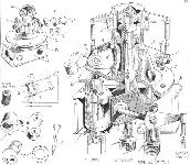
This "skeleton" drawing illustrates the essential features of the head of the Kay Gyroplane. The small plan on the left shows how the rotation of the "Z" crank G imparts a lateral motion to the whole of the head, while the change of incidence for the blade is produced in the same manner with the "Z" cranks G'
-
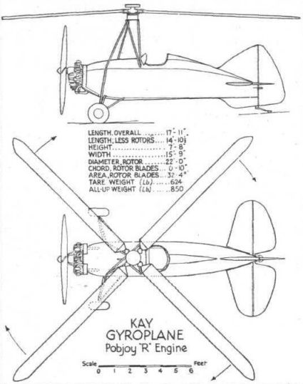
Flight 1934-12 / Flight
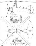
Kay Gyroplane Pobjoy "R" Engine


- Фотографии