
 Wiki
Wiki 
Варианты
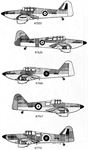
- Miles - Kestrel M.9 / Master I M.9A - 1937 - Великобритания
- Miles - Master II M.19 / Master III M.27 - 1939 - Великобритания
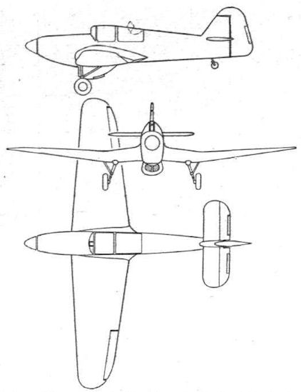
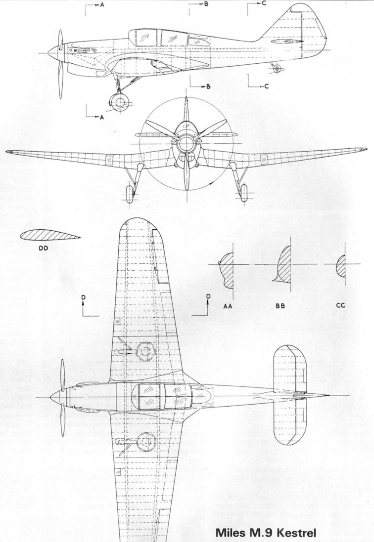
M.9 Kestrel / Master
Miles M.9, M.19, M.24 и M.27 Master
Из-за быстрого совершенствования монопланов в конце 1930-х годов британским ВВС потребовался учебно-тренировочный самолет с характеристиками, близкими к истребительным. Компания "Miles" разработала учебный низкоплан с мотором Rolls-Royce Kestrel XVI мощностью 745 л. с. Когда Министерство авиации прекратило финансирование работ, фирма продолжила проектирование на собственные средства. Прототип, названный Kestrel, выполнил первый полет 3 июня 1937 года. Вскоре прототип продемонстрировал скорость всего на 15 км/ч меньшую, чем у Hurricane. По управляемости самолет мало отличался от Hurricane и Spitfire. Не имея других вариантов, Министерство авиации было вынуждено заказать 11 июня 1939 года у компании "Miles" учебные самолеты под обозначением M.9 Master. В конструкцию потребовали внести ряд изменений, а также установить 715-сильный мотор Kestrel XXX, из-за чего максимальная скорость в сравнении с прототипом упала на 113 км/ч. Тем не менее Master все равно оставался лучшим в мире учебно-тренировочным самолетом. Первый из 900 построенных M.9A Master Mk I выполнил первый полет 31 марта 1939 года.
<...>
Описание:
- M.9 Kestrel / Master
- Flight, July 1939
TRAINER DE LUXE - Flight, November 1939
Britain's Military Aircraft
Фотографии

-
Мировая Авиация 194
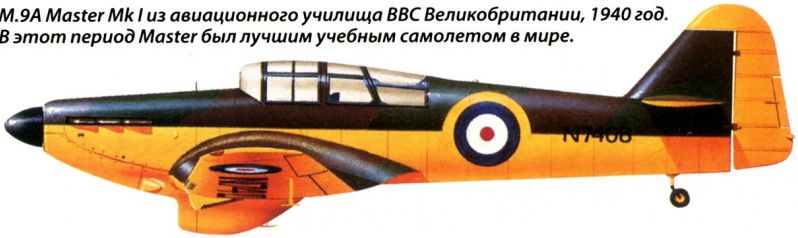
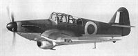
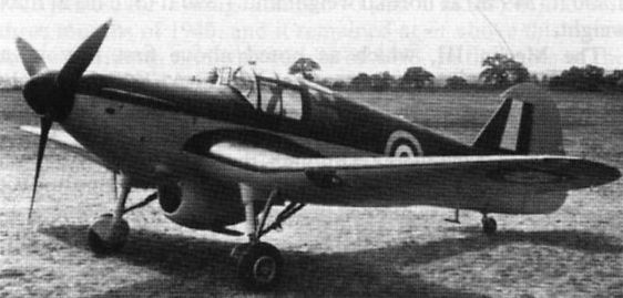
Регистрационный номер: N7408 [7] M.9A Master Mk I из авиационного училища ВВС Великобритании, 1940 год. В этот период Master был лучшим учебным самолетом в мире.
-

Jane's All the World Aircraft 1938 / 03 - All the world's aeroplanes
The Miles R.R. Trainer (Rolls-Royce "Kestrel" engine).
-

Aeroplane Monthly 1980-08 / P.Amos - Miles M.9A Master I /RAF Piston Trainers/ (10)
A "private-venture" machine, the new Miles advanced fighter-trainer is powered with a Kestrel XVI which gives it a top speed of 290 m.p.h.
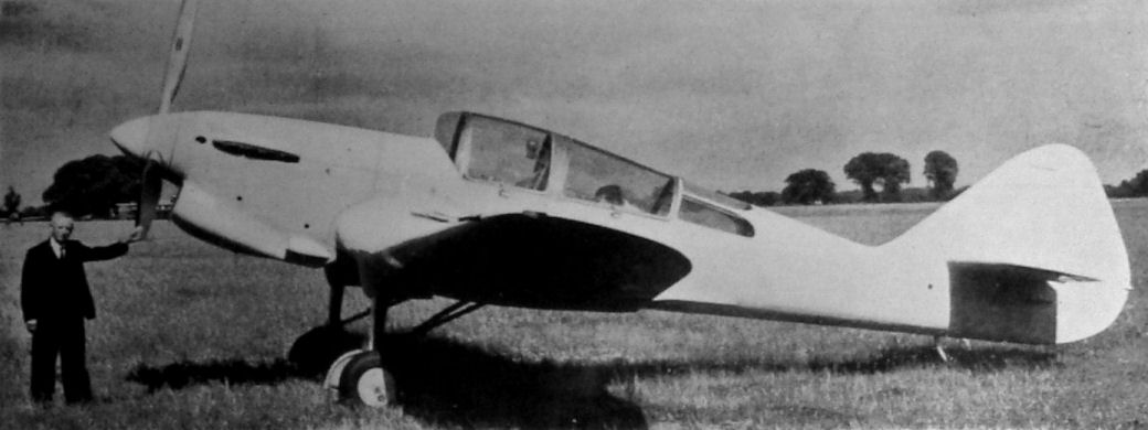
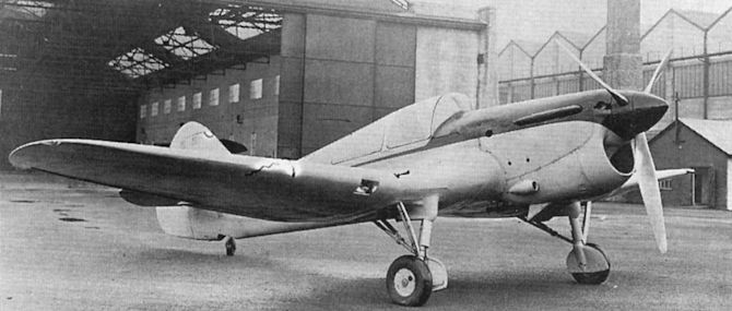
The private-venture Miles Kestrel, later registered U-5, was well ahead of its time. -

Aeroplane Monthly 1989-10 / A.Lumsden, T.Heffernan - Probe Probare: Miles Kestrel/Master (1)
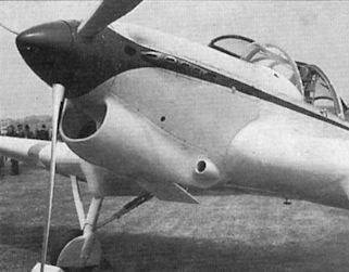
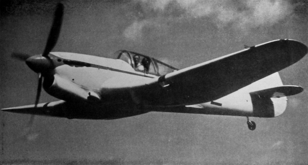
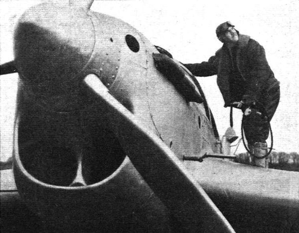
A close-up of the installation of the Rolls-Royce Kestrel XVI and the Kestrel's well-streamlined nose.
-

Flight 1937-09 / Flight
An advanced Kestrel XVI installation in the new Miles trainer/general-purpose military monoplane. The coolant is ethylene glycol.
-

-

Flight 1937-12 / Flight
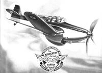
NOT SO PRIVATE: Child of a designer who, until comparatively recently, has concentrated on the production of private-owner types, the new Miles high-speed Service trainer has a number of features which would make it, in 200 h.p. form, an attractive device for the sporting pilot with (very) ample means. Capable of 295 m.p.h., the Miles Kestrel Trainer has great potentialities as a first-line military type. The engine is a Rolls-Royce Kestrel XVI.
-

Jane's All the World Aircraft 1938 / 03 - All the world's aeroplanes
The Miles R.R. Two-seat Fighter Training Monoplane (Rolls-Royce "Kestrel XVI" engine).
-

Flight 1937-07 / Flight
The Miles-Rolls-Royce advanced trainer-general-purpose-fighter-bomber-reconnaissance monoplane does about 290 m.p.h. with a 690/750 h.p. fully supercharged Kestrel XVI.
-

Flight 1938-02 / Flight
The Miles Kestrel Trainer which would make a very good first-line two-seater fighter, having a speed of 295 m.p.h.
-
Aeroplane Monthly 1989-10 / A.Lumsden, T.Heffernan - Probe Probare: Miles Kestrel/Master (1)
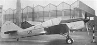
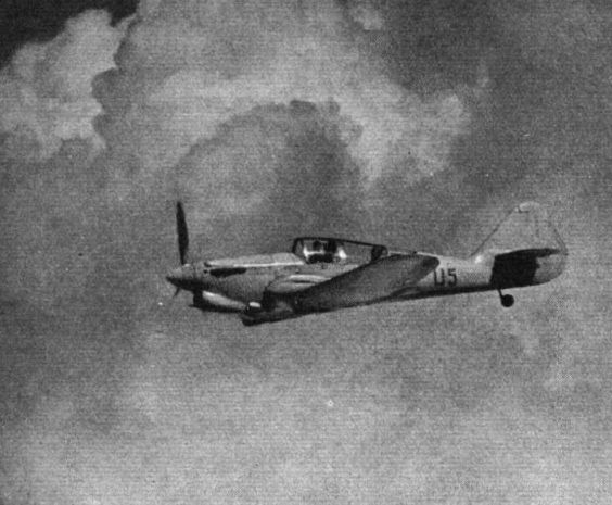
The Kestrel as U 5, with deepened radiator but before modification of the canopy.
-

Aeroplane Monthly 1989-10 / A.Lumsden, T.Heffernan - Probe Probare: Miles Kestrel/Master (1)
The Kestrel with the deeper and more bulbous radiator fairing. It originally had a much sleeker but less accessible installation, with which it made its debut at the 1937 RAF Display at Hendon. Powered by a supercharged 745 h.p. Rolls-Royce Kestrel engine, U 5 had a maximum speed of 296 m.p.h. at 14,500ft - only 15 m.p.h. slower than the front-line Hawker Hurricane.
-


-
Aeroplane Monthly 1989-10 / A.Lumsden, T.Heffernan - Probe Probare: Miles Kestrel/Master (1)
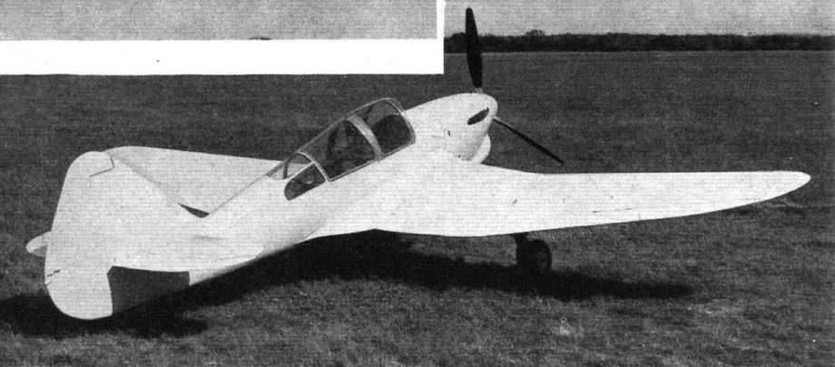
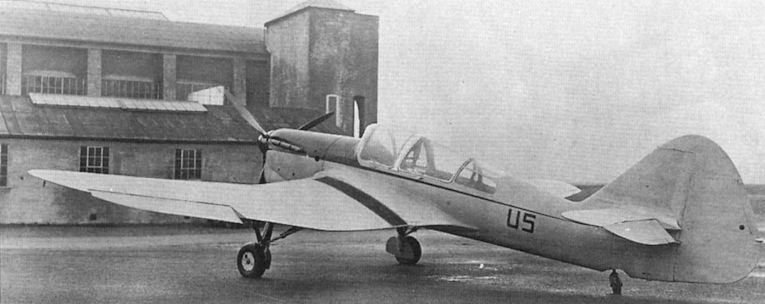
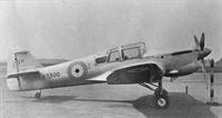
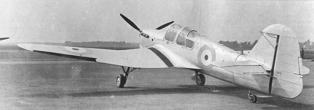
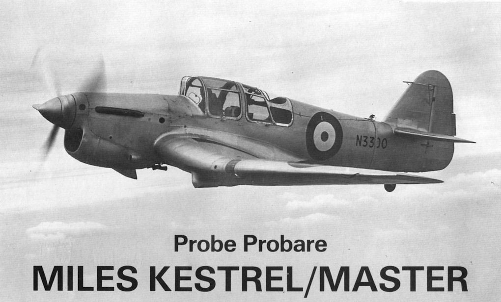
Регистрационный номер: N3300 [5] The Kestrel after it became the Master prototype. Comparison with the picture of the Kestrel reveals the Master's deeper aft fuselage, redesigned fin and rudder, taller windscreen and modified rear canopy.
-

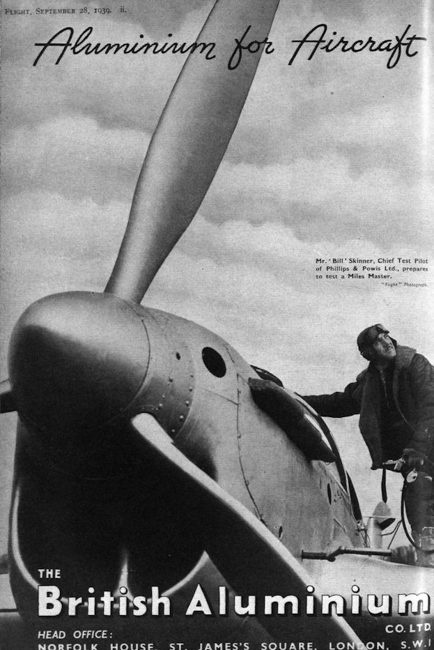
Flight 1939-09 / Flight Advertisements
Mr. ‘Bill’ Skinner, Chief Test Pilot of Phillips & Powis Ltd., prepares to test a Miles Master.
-

Flight 1939-11 / Flight
The late Mr. Skinner about to start in a Miles Master.
-

Aeroplane Monthly 1989-10 / A.Lumsden, T.Heffernan - Probe Probare: Miles Kestrel/Master (1)
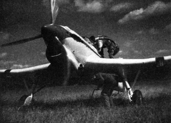
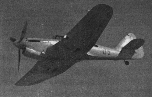
Another view of the Kestrel after modification as the Master prototype. The inverted gull wing allowed short, sturdy undercarriage legs to be used.
-
Aeroplane Monthly 1989-10 / A.Lumsden, T.Heffernan - Probe Probare: Miles Kestrel/Master (1)
Регистрационный номер: N3300 [5] In the transition from prototype to production Master, the radiator was moved from the chin installation seen on N3300 here to a new and distinctive position under the mainspar.
-
Aeroplane Monthly 1989-10 / A.Lumsden, T.Heffernan - Probe Probare: Miles Kestrel/Master (1)
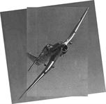
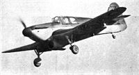
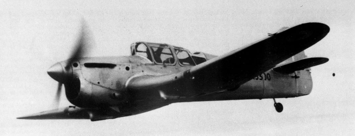
A delightful impression of the prototype Miles M.9A Master I two-seater advanced trainer (Rolls-Royce Kestrel XXX).
-

Aeroplane Monthly 1980-08 / P.Amos - Miles M.9A Master I /RAF Piston Trainers/ (10)
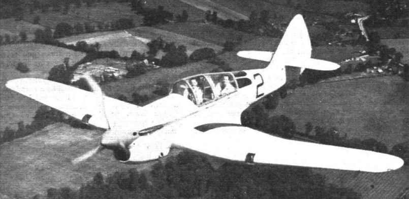
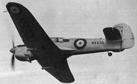
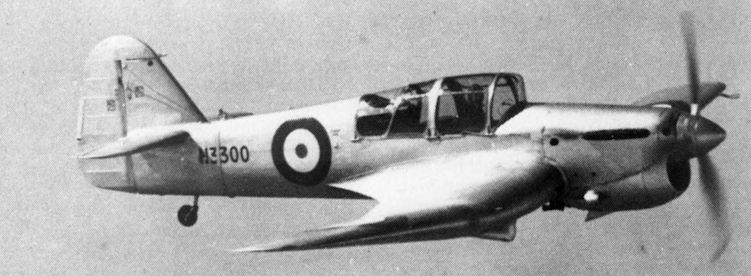
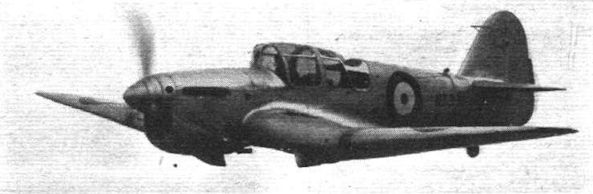
Регистрационный номер: N3300 [5] View of the Master prototype N3300 in flight during 1938-39. The extended rear fuselage and production-standard tail surfaces eliminated the directional hunting encountered during early Martlesham trials.
-

Aeroplane Monthly 1980-08 / P.Amos - Miles M.9A Master I /RAF Piston Trainers/ (10)
Регистрационный номер: N3300 [5] N3300, the first prototype Master I, converted from the private venture Kestrel prototype, was delivered to the RAE in October 1938.
-

-

Aeroplane Monthly 1989-10 / A.Lumsden, T.Heffernan - Probe Probare: Miles Kestrel/Master (1)
Регистрационный номер: N3300 [5] The Miles Kestrel after modification as the prototype Master, N3300. Initially registered U 5 and flown for the first time on June 3, 1937, the Kestrel reappeared as N3300 in 1938. The strap visible around the rear fuselage in this photograph is part of the anti-spin parachute attachment; a release cable may be seen running forward to the cockpit.
MASTERLY: The Miles Master high-speed advanced trainer as now in large-scale production for the R.A.F. Actually, the machine seen here (with Mr. Skinner taking it up to 25,000ft. for tests), is the revised prototype with Rolls-Royce Kestrel XVI engine which gives it a top speed of 295 m.p.h. The production version will have the less powerful Kestrel XXX and will do nearly 270 m.p.h. -

Aeroplane Monthly 1989-11 / A.Lumsden, T.Heffernan - Probe Probare: Miles Kestrel/Master (2)
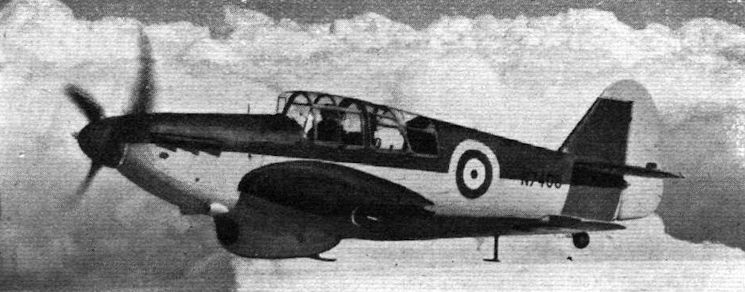
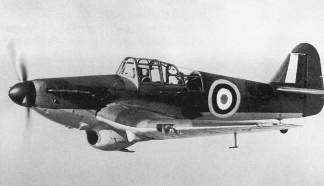
Регистрационный номер: N7408 [7] The first production Miles Master I, N7408, was the first of an initial batch of Mk Is delivered to the RAF between July 1939 and September 1940. On August 28, 1940 N7408 hit a balloon cable and crash-landed at Smethwick, Birmingham.
-

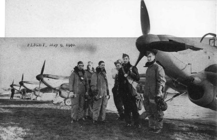
Flight 1939-05 / Flight
Регистрационный номер: N7408 [7] THE NEW MASTER: In its production form, the Miles Master two-seater advanced trainer (Rolls-Royce Kestrel XXX) has a re-arranged radiator and certain other minor improvements.
-
Aeroplane Monthly 1998-10 / T.Neil - A Servant of Four Masters
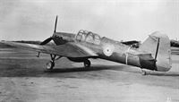
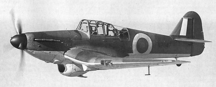
Регистрационный номер: N7547 [2] A fine study of Master I N7547, with the mouth-like radiator intake and undercarriage “knuckle” well shown.
The in-line Rolls-Royce Kestrel engine of the Master I gave its nose a far different shape from that of the radial-engined Mks II and III. Not being “overly fond” of this early variant of the breed, the author was somewhat alarmed when one was wheeled out to replace the damaged Mk III. -

Мировая Авиация 194
Регистрационный номер: N7547 [2] С мотором жидкостного охлаждения и огромным радиатором Master Mk I смотрелся необычно. Большинство самолетов Master эксплуатировалось в Силэнде, Халлавингтоне и Монтроузе.
-

Aeroplane Monthly 1980-08 / P.Amos - Miles M.9A Master I /RAF Piston Trainers/ (10)
Регистрационный номер: N7408 [7] Stages in the evolution of commercial aircraft. The Hampstead.
-

Aeroplane Monthly 1980-08 / P.Amos - Miles M.9A Master I /RAF Piston Trainers/ (10)
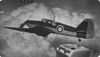
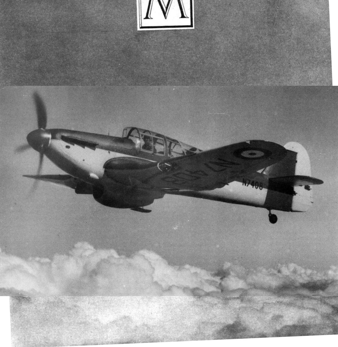
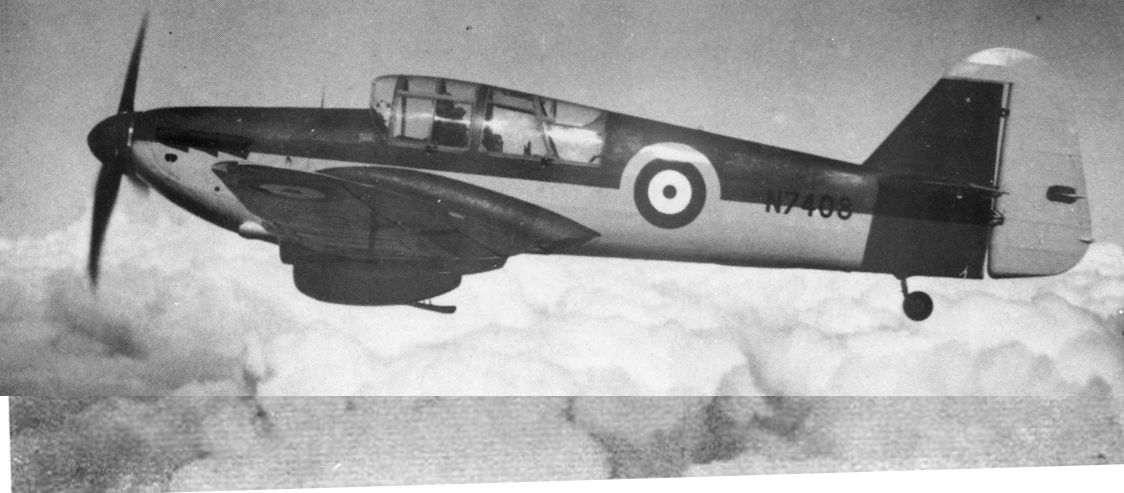
Регистрационный номер: N7408 [7] Mr. H. W. C. Skinner, chief test pilot, does a "straight and level" above the clouds on a production Master.
The first production Miles Master I, N7408, was the first of 900 Mk Is delivered to the RAF, the first aircraft entering service in mid-1939. -

Aeroplane Monthly 1989-11 / A.Lumsden, T.Heffernan - Probe Probare: Miles Kestrel/Master (2)
Регистрационный номер: N7408 [7] Another view of Master I N7408. The general similarity of the type with the Spitfire and the Hurricane is obvious: it made the pupil’s transition from Tiger Moth to front-line fighter a much less daunting step.
-

Aeroplane Monthly 1990-10 / J.Meadows - Flying for fun (5)
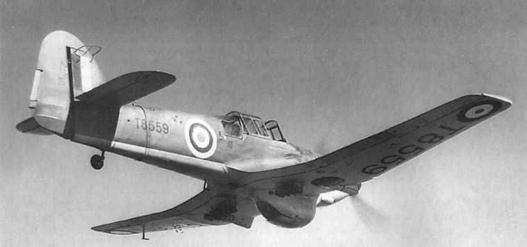
Регистрационный номер: T8559 [2] Following a period with the A&AEE, this clipped-wing Miles Master 1 spent time with No 9 Pilots Advanced Flying Unit (PAFU) until it crashed near the River Tay in March 1944.
-
Flight 1940-05 / Flight Advertisements
Регистрационный номер: N7408 [7] The Miles Master, an advanced single-engined machine;
-

Aeroplane Monthly 1998-10 / T.Neil - A Servant of Four Masters
Регистрационный номер: T8559 [2] Another distinctive feature of the Master I was the curvaceous radiator housing beneath the cockpit. Two successive Mk Is in which the author attempted to complete his flight developed powerplant problems and had to return to Hawarden.
-
Flight 1940-12 / Flight
The Miles Master (Kestrel XXX) is an advanced trainer with very distinctive features.
-

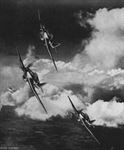
Flight 1940-05 / Flight
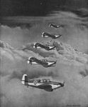
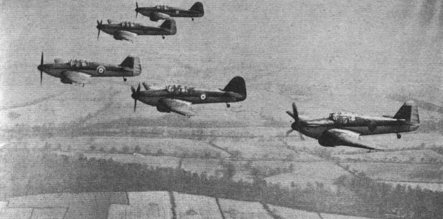
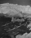
ADVANCED FORMATION: Miles Master advanced trainers (Rolls-Royce Kestrel XXX) in a commendable vic formation. The Master reproduces many of the characteristics of such machines as the Hurricane and Spitfire and with a more powerful engine would make a very useful first-line fighter.
-

История Авиации 39 / В.Блинов - "Дон" Джентиль /Асы мира/
Звено английских тренировочных самолетов «Майлс Мастер» из состава учебной части, дислоцировавшейся в Силэнде (Флинтшер, Великобритания), которая занималась подготовкой лётного состава для Королевских ВВС из числа американских добровольцев.
-
-

Aeroplane Monthly 1990-09 / J.Meadows - Flying for fun (4)
Регистрационный номер: N7990 Miles Master Is, possibly those of 9 FTS, with N7990 nearest the camera.
-

Aeroplane Monthly 1980-08 / P.Amos - Miles M.9A Master I /RAF Piston Trainers/ (10)
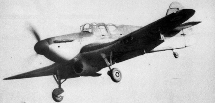
Регистрационный номер: N7420 [2] N7420 on finals, with full flap and undercarriage down.
-
Flight 1939-12 / Flight
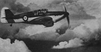
Регистрационный номер: N7420 [2] MASTERFUL APPROACH: A Miles Master two-seater advanced trainer (Rolls-Royce Kestrel XXX) approaches to land with flaps down. A considerable number of these machines is already in service.
-
Air-Britain Aeromilitaria 1983-03 / Miles Master I
Регистрационный номер: N7410 [5] The third production Master I, N7410, taken at the A&AEE. It was initially flown to Martlesham Heath but was flown to Boscombe Down shortly after war was declared. It eventually became instructional airframe 2551M.
-

Air-Britain Aeromilitaria 1983-03 / Miles Master I
Регистрационный номер: N7410 [5] N7410 was the third production aircraft and was delivered to the Aeroplane & Armament Experimental Establishment at Martlesham Heath in August 1939, following N7409 which was intended for general handling trials.
N7410 was equipped with, bomb racks for use as a bombing trainer, having racks for small practice bombs mounted on the rear centre-section just outboard of the fuselage. -

Air-Britain Aeromilitaria 1983-03 / Miles Master I
Регистрационный номер: N7410 [5] -

Air-Britain Aeromilitaria 1983-03 / Miles Master I
Регистрационный номер: N7410 [5] The third production Master I, N7410, taken at the A&AEE. It was initially flown to Martlesham Heath but was flown to Boscombe Down shortly after war was declared. It eventually became instructional airframe 2551M.
-

Aeroplane Monthly 1980-08 / P.Amos - Miles M.9A Master I /RAF Piston Trainers/ (10)
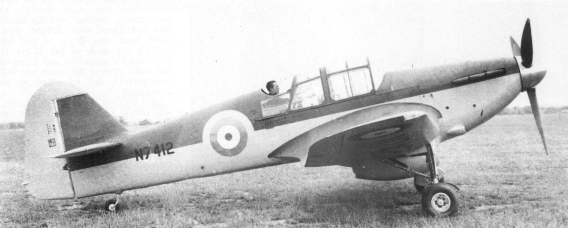
Регистрационный номер: N7412 Master N7412, seen with the rear seat raised, was later converted to become the prototype M24 single-seat Master Fighter.
-
Aeroplane Monthly 1989-05 / G.Levett - From Penguin into Eagle (4)
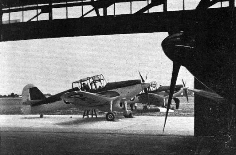
Регистрационный номер: N7410 [5] Miles Master advanced-training monoplanes with Rolls-Royce Kestrel XXX engines. The Kestrel XXX has been specially developed to meet training requirements.
Line-up of Master Is. The prototype first flew in 1938 but by the time war broke out in September 1939 only a handful were in service. Masters of No 5 EFTS are pictured here.
Factory-fresh Masters, 1939. N7410, second from the front, was delivered to the A & AEE and became 2551M in March 1941. -

Aeroplane Monthly 1989-11 / A.Lumsden, T.Heffernan - Probe Probare: Miles Kestrel/Master (2)
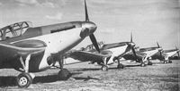
Регистрационный номер: N7428, N8014 ADVANCED TRAINERS: Flying training schools are now receiving batches of Miles Master I advanced training monoplanes with Rolls-Royce Kestrel XXX engines. These machines are not only fast and “easy on the eye” but reproduce more nearly than any comparable type the characteristics of the modern fighter.
A line-up of newly-delivered Miles Master Is, probably at No 5 FTS, RAF Sealand, in November 1939. The one with serial number visible, N7428, later went to No 6 Anti-Aircraft Cooperation Unit and was destroyed in a collision with Miles Master N8014 near Oswestry on June 15, 1942.
Closely resembling the Miles M.9 Kestrel, the Master I was powered by a derated Rolls-Royce Kestrel XXX, making it 70 m.p.h. slower than its predecessor. Its handling characteristics made it an ideal fighter trainer. -

-

Flight 1940-05 / Flight
More RAF FTS pupils undergoing training on Master Is “somewhere in Southern England" according to the original caption. Many Battle of Britain pilots were trained on the Master, and the Miles team regarded the design as the firm's major contribution to the war effort.
-
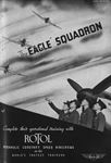
Flight 1940-10 / Flight
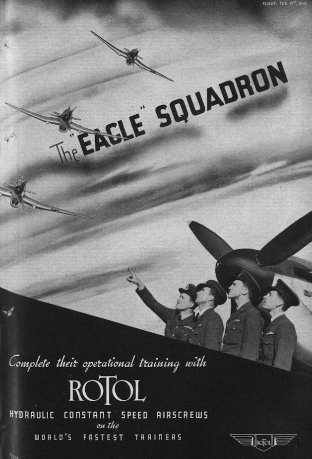
Регистрационный номер: N7492 Pupils of the Eagle Squadron being introduced by their R.A.F. instructors to the Miles Master Trainer on which they will receive their advanced training.
-

Flight 1939-11 / Flight
The nose of a Miles Master advanced trainer (Rolls-Royce Kestrel XXX). It will be seen that the radiator is mounted under the fuselage behind the engine.
-

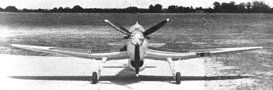
Flight 1939-07 / Flight
There is no doubt that, in the Master, Service trainees will have "a real aeroplane." The top speed of over 260 m.p.h. can be credited on examining this view.
-

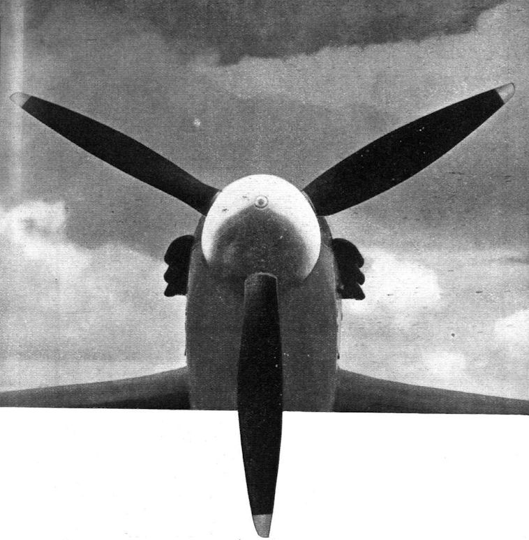
Flight 1939-07 / Flight
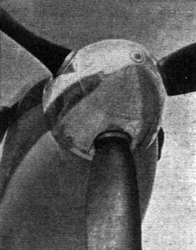
A V.D.M. spinner on the Miles Master
-

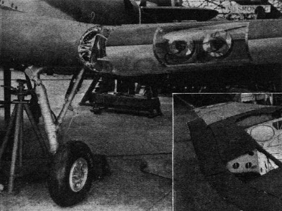
Flight 1939-07 / Flight
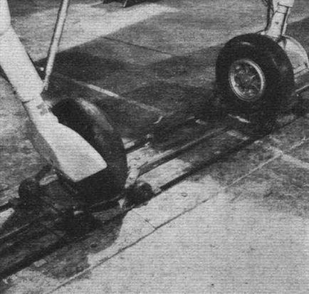
Undercarriage and landing light installation. The wheels turn 90° during retraction.
-

Flight 1939-07 / Flight
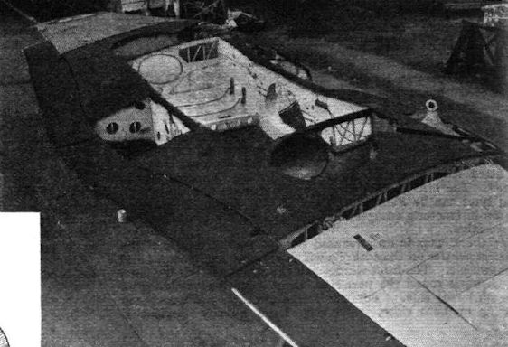
The complete wing of a Master showing the formation of the centre gulled portion.
-
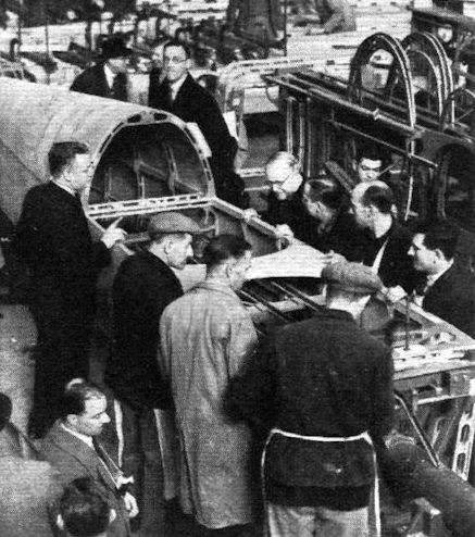
Flight 1939-02 / Flight
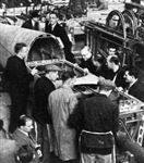
SIR KINGSLEY WOOD looks into a Miles Master airframe on its jig during his visit to the new Phillips and Powis factory. The fuselage appears to have been modified to accommodate the new tail unit.
-

Flight 1939-07 / Flight
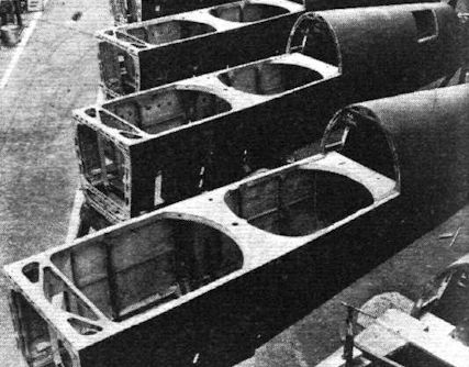
Semi-monocoque fuselages in train for Masters.
-

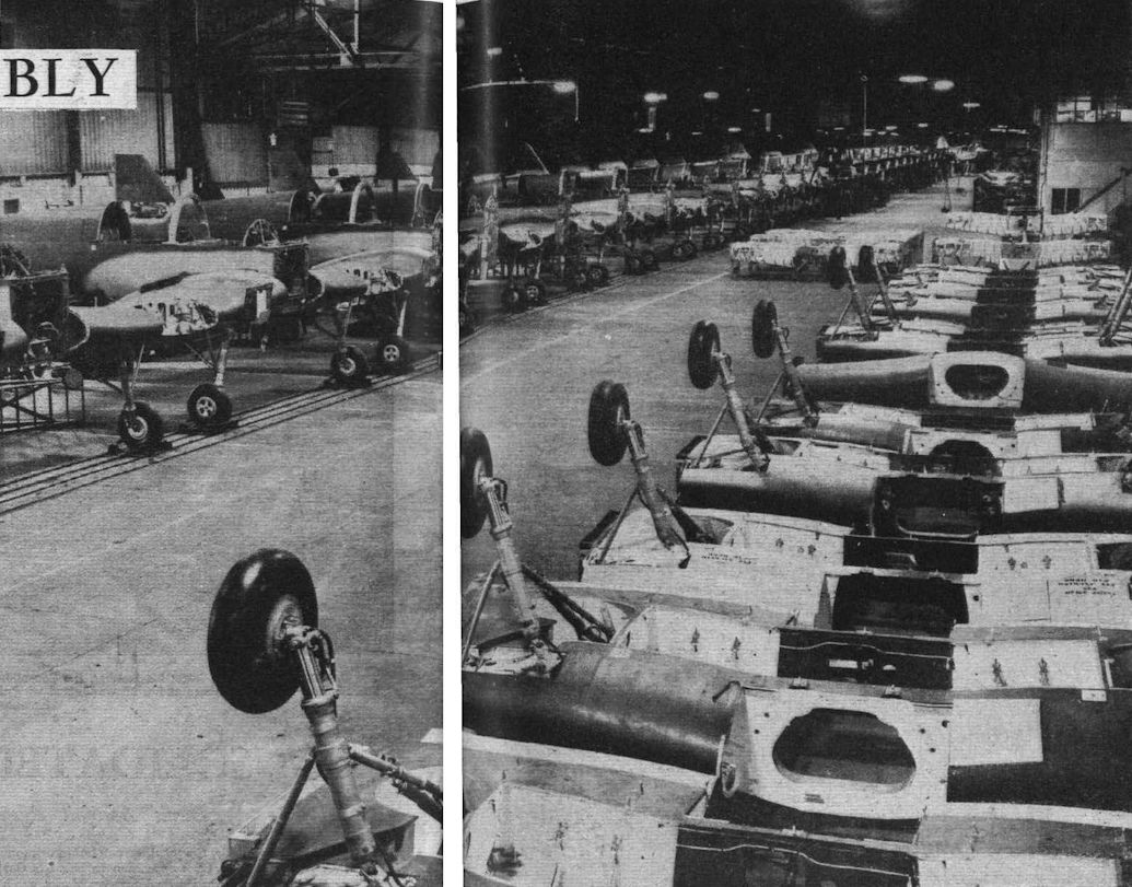
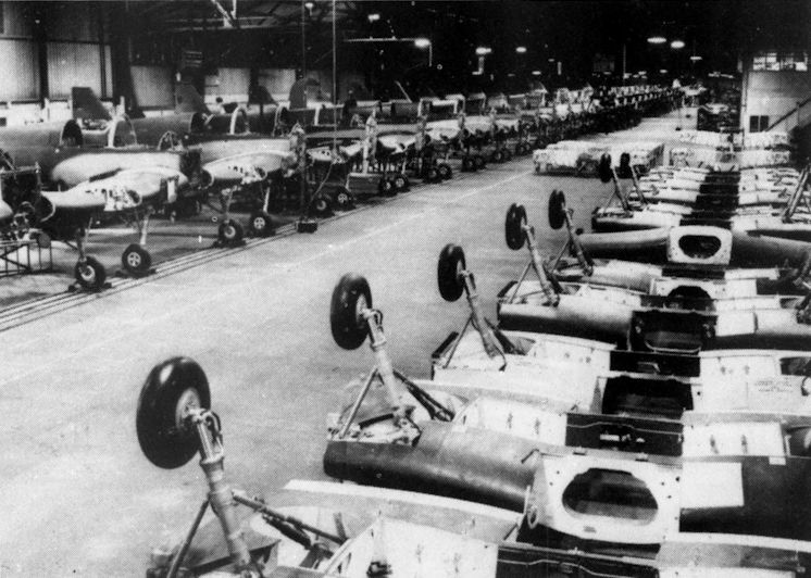
Flight 1940-08 / Flight
To maintain an even spacing between aircraft the trolleys are linked up by rods.
-

Flight 1940-08 / Flight
Centre-sections ready for transfer to assembly line opposite.
-

Aeroplane Monthly 1980-08 / P.Amos - Miles M.9A Master I /RAF Piston Trainers/ (10)
Production at Woodley, with centre sections ready for transfer to the advanced track assembly line opposite. This system enabled the first 500 Master Is to be delivered between July 1939 and September 1940, a production rate of 33 machines per month.
-

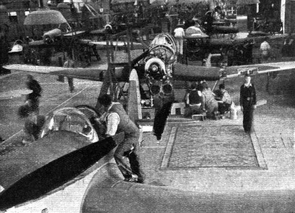
Aeroplane Monthly 1989-11 / A.Lumsden, T.Heffernan - Probe Probare: Miles Kestrel/Master (2)
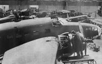
Miles Masters being constructed on the novel (for Britain at least) track assembly system at Woodley. The whole production line moved forward as a unit every 4hr, each assembly operation taking 4hr to complete.
Installation of Rolls-Royce engines. At the far end the line goes round the corner to where wings are fitted. -

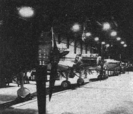
Flight 1940-08 / Flight
Nearing the final stage, where Rotol airscrews are fitted to the Rolls-Royce engines.
-
Flight 1940-08 / Flight
The fuselages are maintained in a horizontal position by having the tail wheels running in a raised rail or trough.
-

Flight 1939-07 / Flight
Miles Masters (Rolls-Royce Kestrel XXX) on the production line at Reading.
-
Aeroplane Monthly 1979-03 / L.Curtis - Anything To Anywhere (3)
An ATA maintenance hangar "somewhere in England" in 1942. Behind the Lockheed Hudson are a Hurricane, Demon K4411, an Oxford, Master W8905, an Argus, a Tutor, a Havard and the tail of an Anson. All were used either for the training or movement of ATA pilots.
Другие самолёты на фотографии: Airspeed Oxford / AS.10 - Великобритания - 1937Avro Anson / Type 652 - Великобритания - 1935Avro Tutor/Sea Tutor/Prefect / Type 621/646/626 - Великобритания - 1929Fairchild C-61 Forwarder / Model 24 / Argus - США - 1932Hawker Demon - Великобритания - 1932Hawker Hurricane - Великобритания - 1935Lockheed Hudson A-28 / A-29 - США - 1938North American T-6 Texan / AT-6 Harvard - США - 1935


-

Air International 1987-05 / Fighter A to Z
The Miles M.24 makeshift six-gun fighter developed for emergency use during the Battle of Britain.
-

Flight 1940-01 / Flight
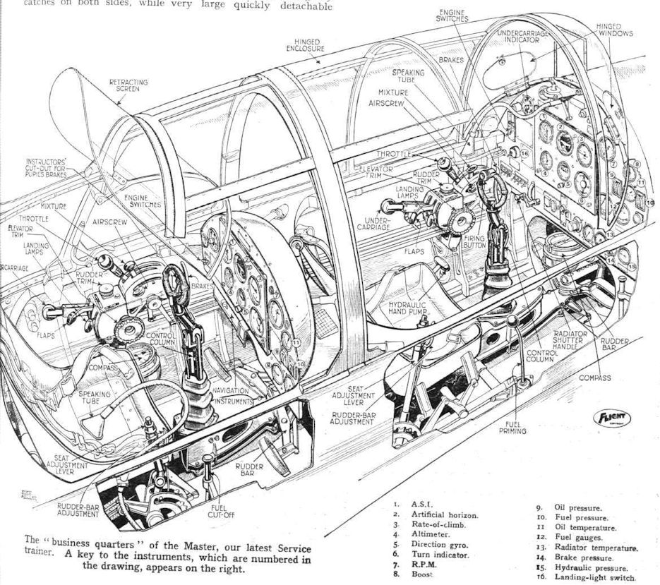
THE WHOLE WORKS: The Miles Master advanced trainer is fitted with all the dials and devices to be found in the cockpits of our latest fighters and bombers.
-
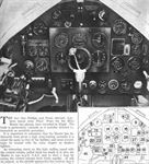
Flight 1940-04 / Flight
INSTRUMENT BOARD. 1, Flaps Position Indicator; 2, Airspeed Indicator Correction Card; 3, Speaking Tube Connection; 4, Reflector Sight Lamp Socket; 5, Reflector Sight Dimmer Switch; 6, Cockpit Lamps Dimmer Switch (Port); 7, Undercarriage Position Indicator; 8, Instrument Flying Hood Release; 9, Engine Revolution Indicator; 10, Cockpit Lamps Dimmer Switch (Starboard); 11, Signalling Switchbox; 12, Main Magneto Switches and Undercarriage Indicator Switch; 13. Oxygen Regulator; 14, Airspeed Indicator; 15, Artificial Horizon; 16, Rate of Climb Indicator; 17, Oil Temperature Thermometer; 18, Oil Pressure Gauge; 19, Boost Pressure Gauge; 20, Fuel Pressure Gauge; 21, Cockpit Lamp; 22, Landing Lamps Switch; 23, Time of Flight Cock; 24, Altimeter; 25, Directional Gyroscope; 26, Turn and Bank Indicator; 27, Fuel Contents Indicator (Port Tank); 28, Fuel Contents Indicator (Starboard Tank); 29, Fire Extinguisher Switch (under Flap); 30, Bomb Selector Switches; 31, Radiator Flap Indicator; 32, Bomb Jettison Switch; 33, Oil Cock; 34. Starting Magneto Switch; 35, Engine Priming Pump; 36, Pneumatic System Pressure Gauge; 37, Radiator Temperature Gauge; 38, Fuel Contents Indicator Switch; 39, Brake Triple Pressure Gauge; 40, Hydraulic System Pressure Gauge; 41, Control Box; 42, Radiator Flap Control; 43. P.6 Compass.
-
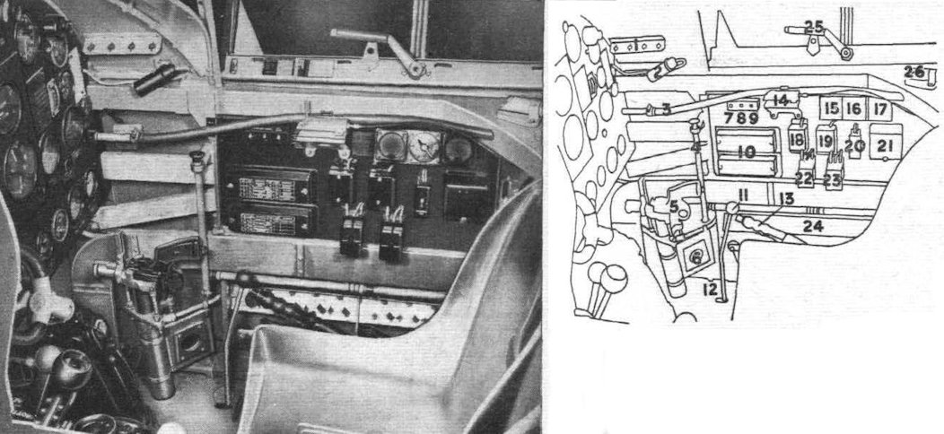
Flight 1940-04 / Flight
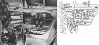
STARBOARD SIDE OF COCKPIT. 1, Stowage for Gun Reflector Sight Lamps; 2, Cockpit Lamp; 3, Fire Extinguisher Bayonet Connection; 4, Fuel Cock Control; 5, Signal Pistol in Mounting; 6, Cine-camera Gun Footage Indicator Mounting; 7, Navigation Lamps Switch; 8, Cine-camera Gun Switch; 9, Pitot Head Heating Switch; 10, Fuse Boxes; 11, Fuel System Priming Lever; 12, Rudder Bar Adjustment Lever; 13, Seat-operating Handle and Locking Plunger; 14, Safety Harness Release Gear; 15, Voltmeter; 16, Charge-regulating Switch; 17, Ammeter; 18, Fuse Boxes; 19, Fuse Boxes; 20, Resistance Unit; 21, Accumulator Cut-out; 22, Relay Switch; 23, Relay Switch; 24, Stowage for Signal Pistol Cartridges; 25, Emergency Door Handle; 26, Starting Handle Stowage.
-
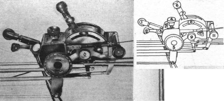
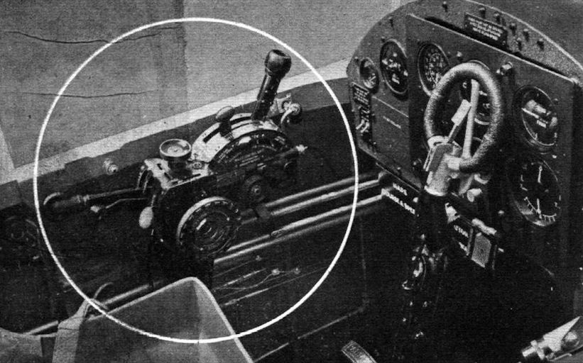
Flight 1940-04 / Flight
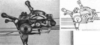
CONTROL BOX. 1, Undercarriage Selector Lever; 2, Flaps Selector Lever; 3, Landing Lamps Control Lever; 4, Rudder Trimming Tab Control; 4a, Rudder Trimming Tab Indicator; 5, Elevator Trimming Tabs Control; 5a, Elevator Trimming Tabs Indicator; 6, Throttle Control Lever and Bomb Firing Switch; 7, Mixture Control Lever; 8, Airscrew Pitch Control Lever; 9, Engine Controls Friction Adjuster; 10, Boost Control Cut-out; 11, Landing Lamps Control Friction Adjuster.
-

Flight 1939-07 / Flight Advertisements
THE MILES MASTER is fitted with an Engine Control Unit, designed and constructed jointly by H. M. Hobson (Aircraft and Motor) Components Ltd. and Phillips & Powis Ltd. under HOBSON PATENTS. It incorporates in one unit the following Controls
- THROTTLE - MIXTURE - BOOST CUT-OUT - FLAPS - C.P. AIR SCREWS
- LANDING LIGHTS - ELEVATOR - RUDDER TRIM - BOMB RELEASE
- RETRACTABLE UNDERCARRIAGE WITH THROTTLE OPERATED WARNING DEVICE -

Flight 1939-07 / Flight
The “business quarters” of the Master, our latest Service trainer. A key to the instruments, which are numbered in the drawing, appears on the right.
-

Aeroplane Monthly 1980-08 / P.Amos - Miles M.9A Master I /RAF Piston Trainers/ (10)
A closeup of the pupil and instructor positions in the Master I.
-
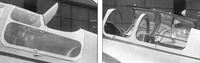
Aeroplane Monthly 1989-10 / A.Lumsden, T.Heffernan - Probe Probare: Miles Kestrel/Master (1)
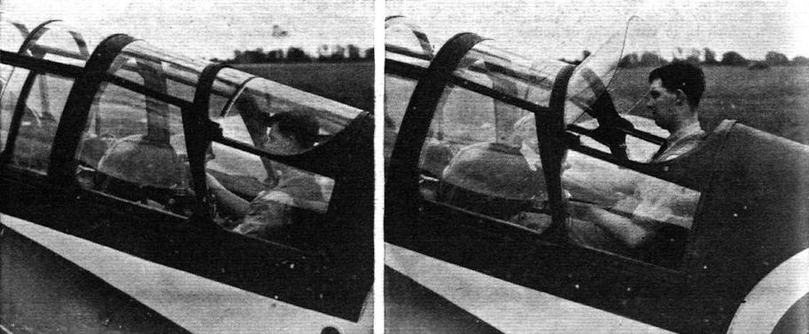
Left, the Kestrel’s rear cockpit after the first modification to raise the roof. Right, the Kestrel with the front hood and modified instructor's hood open, showing the operating handle for the hinged aft windscreen.
-

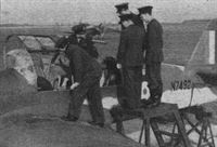
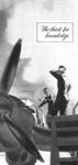
Flight 1939-07 / Flight
Showing how, for landing, the instructor can raise himself to obtain a good view. The raising of the windscreen is automatic.
-

Aeroplane Monthly 1984-01 / L.Coombs - Cockpits of the RAF (4)
The retractable windscreen of the Miles Master lifted automatically when the instructor raised his seat, giving his improved vantage point some protection from the elements.
-

Aeroplane Monthly 1990-09 / J.Meadows - Flying for fun (4)
Rear cockpit of the Master 1, showing the instructor's position.


-

Flight 1939-05 / Flight
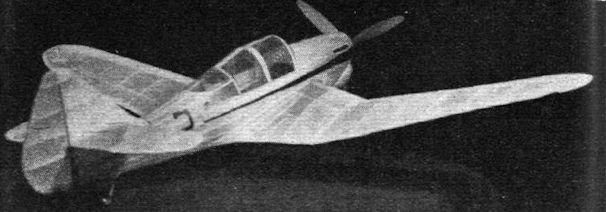
The flying scale model - Miles Master
-

-
-
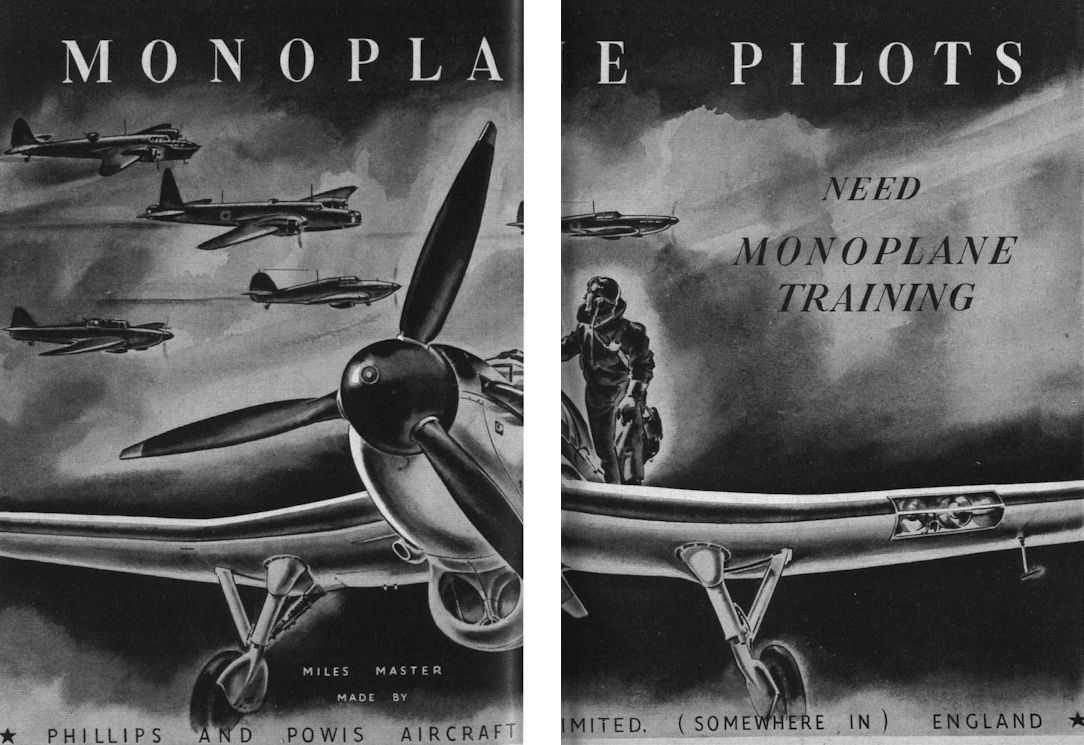
Flight 1939-02 / Flight Advertisements
Регистрационный номер: L1111 -

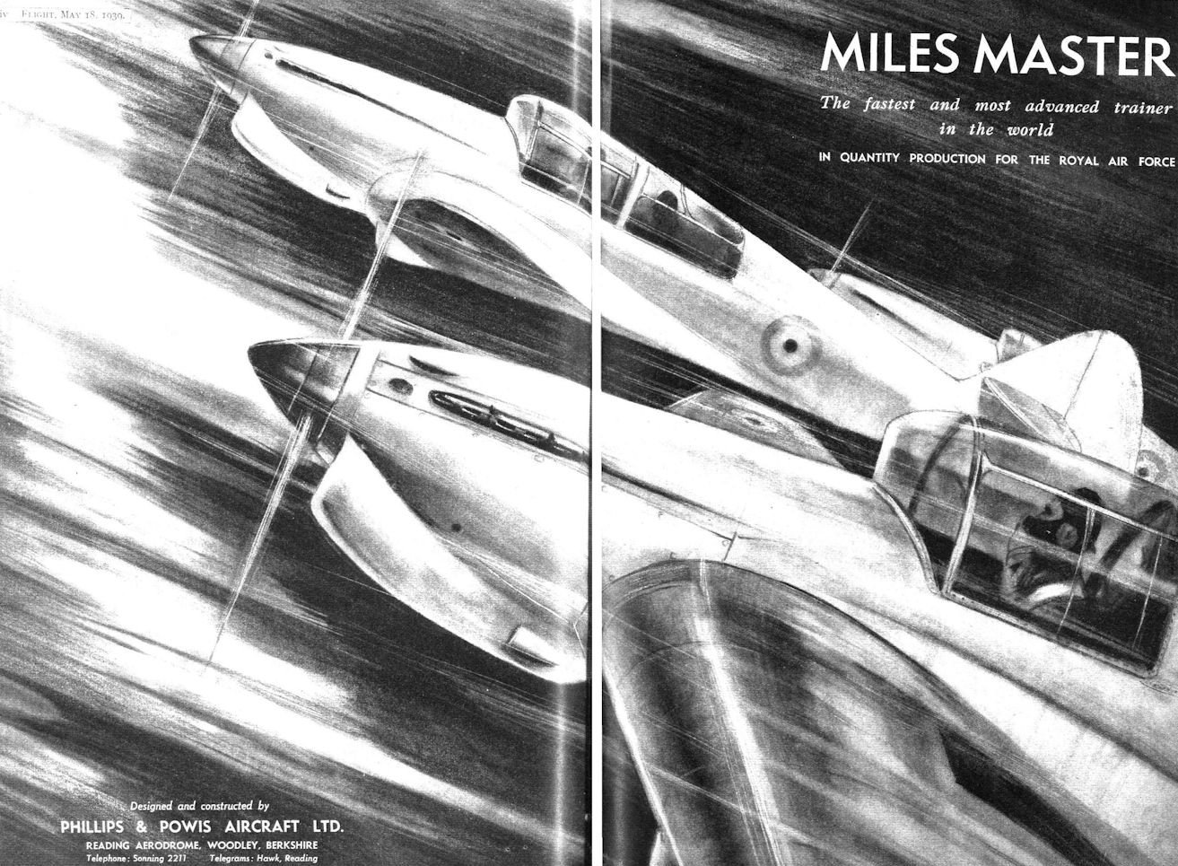
Flight 1939-05 / Flight Advertisements
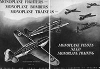
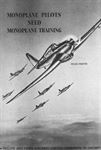
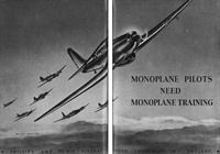
MILES MASTER The fastest and most advanced trainer in the world IN QUANTITY PRODUCTION FOR THE ROYAL AIR FORCE


-

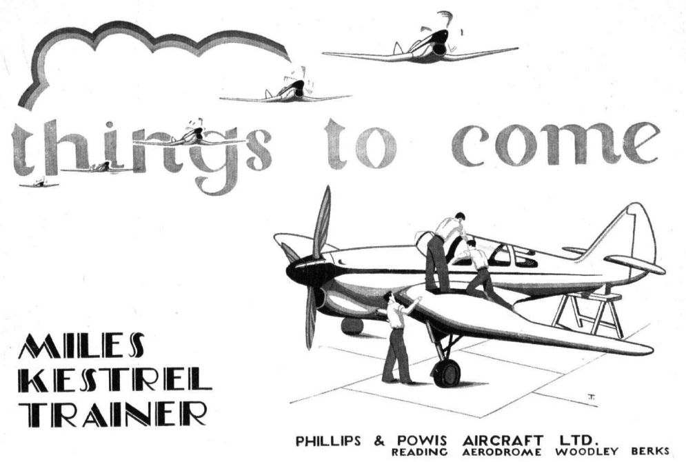
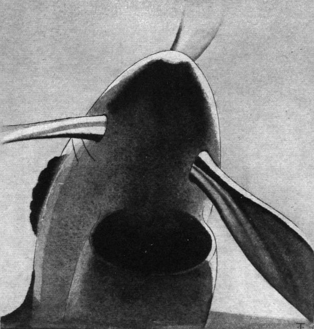
Flight 1937-11 / Flight Advertisements
The Basking Shark is extremely efficient from the streamline point of view, but then the Basking Shark has been developed for efficiency, just as the Miles Kestrel Trainer has been developed, by careful elimination of the unessential.
-

Flight 1939-07 / Flight Advertisements
ROTOL VARIABLE PITCH AIRSCREWS are fitted on ROLLS-ROYCE KESTREL XXX ENGINES installed in the MILES MASTER AIRCRAFT manufactured by Phillips & Powis Aircraft Ltd., of Reading
-

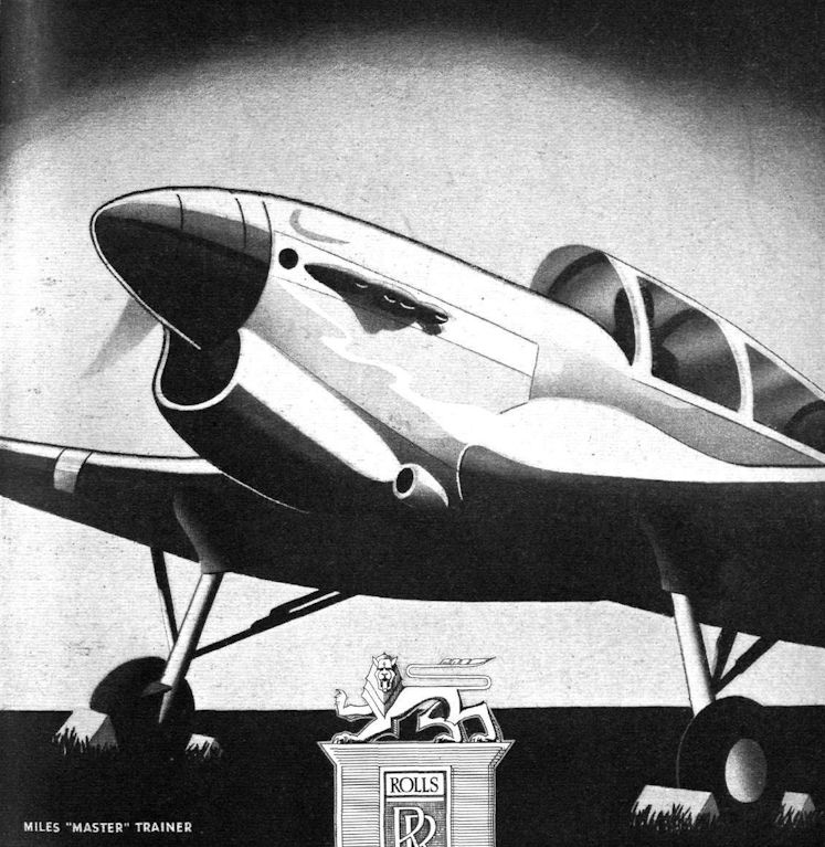
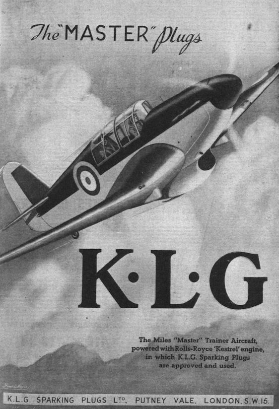
Flight 1939-12 / Flight Advertisements
Miles "Master" Trainer
-
-
-
Flight 1940-07 / Flight Advertisements
A view British air travellers (except the R.A.F.) will not see again until the war is over. The Jersey coastline with a DH Flamingo en route to Heston.
-
Flight 1940-03 / Flight Advertisements
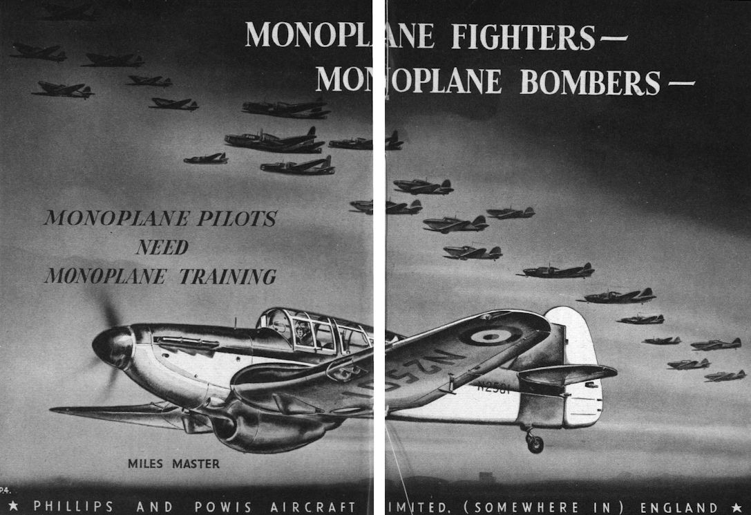
Регистрационный номер: N2501 [2] -
Flight 1940-02 / Flight Advertisements
Регистрационный номер: N2501 [2] -

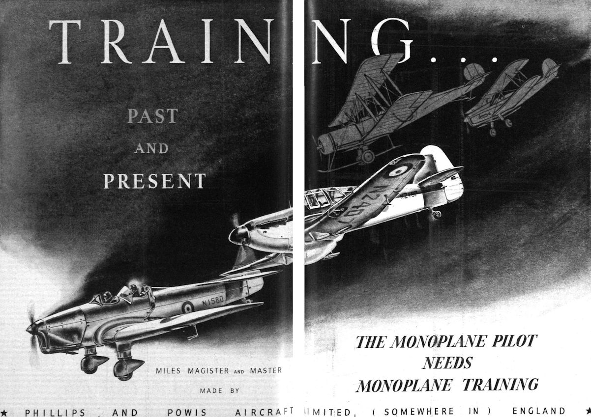
Flight 1939-12 / Flight Advertisements
Регистрационный номер: N2407 Другие самолёты на фотографии: Miles Magister / M.14 - Великобритания - 1937
-
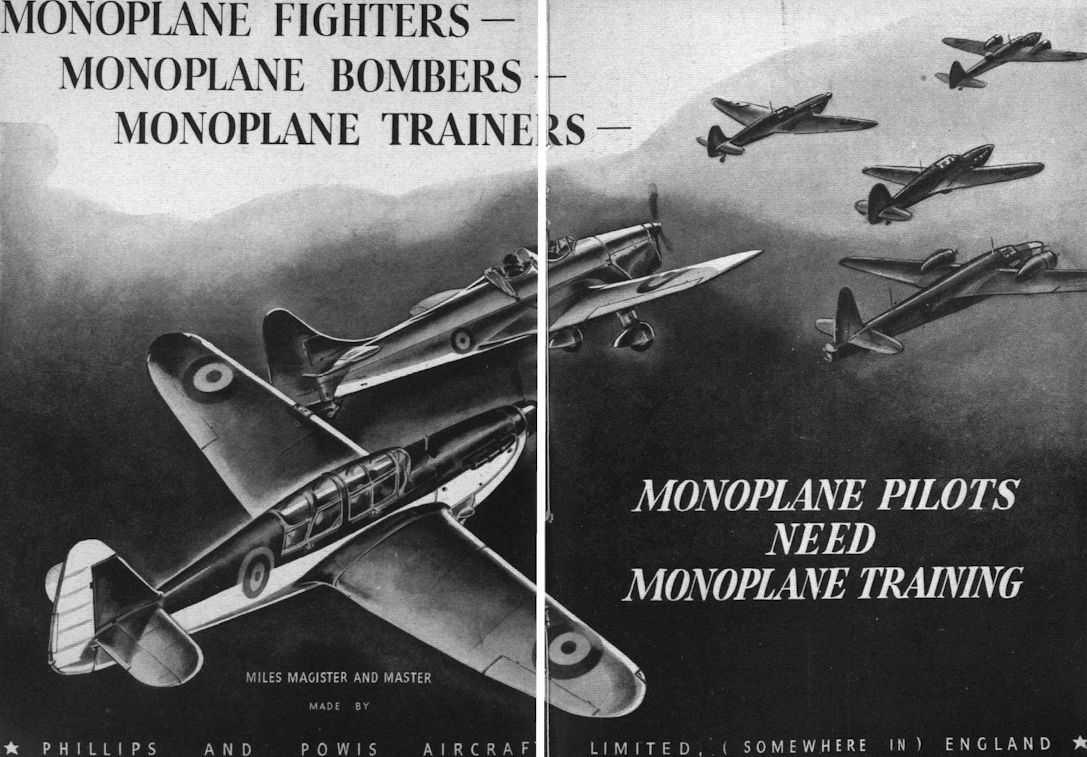
Flight 1940-02 / Flight Advertisements
Другие самолёты на фотографии: Miles Magister / M.14 - Великобритания - 1937
-
Flight 1940-03 / Flight Advertisements
A manually trained 20mm. Oerlikon shell-gun. This weapon is now being fitted on certain bombers and other large aircraft.
-
-

-
-
-
-
-

Flight 1939-07 / Flight
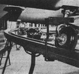
A typical control run on the Master, showing the application of the neat rubber-tyred ball races.
-

-

-

-

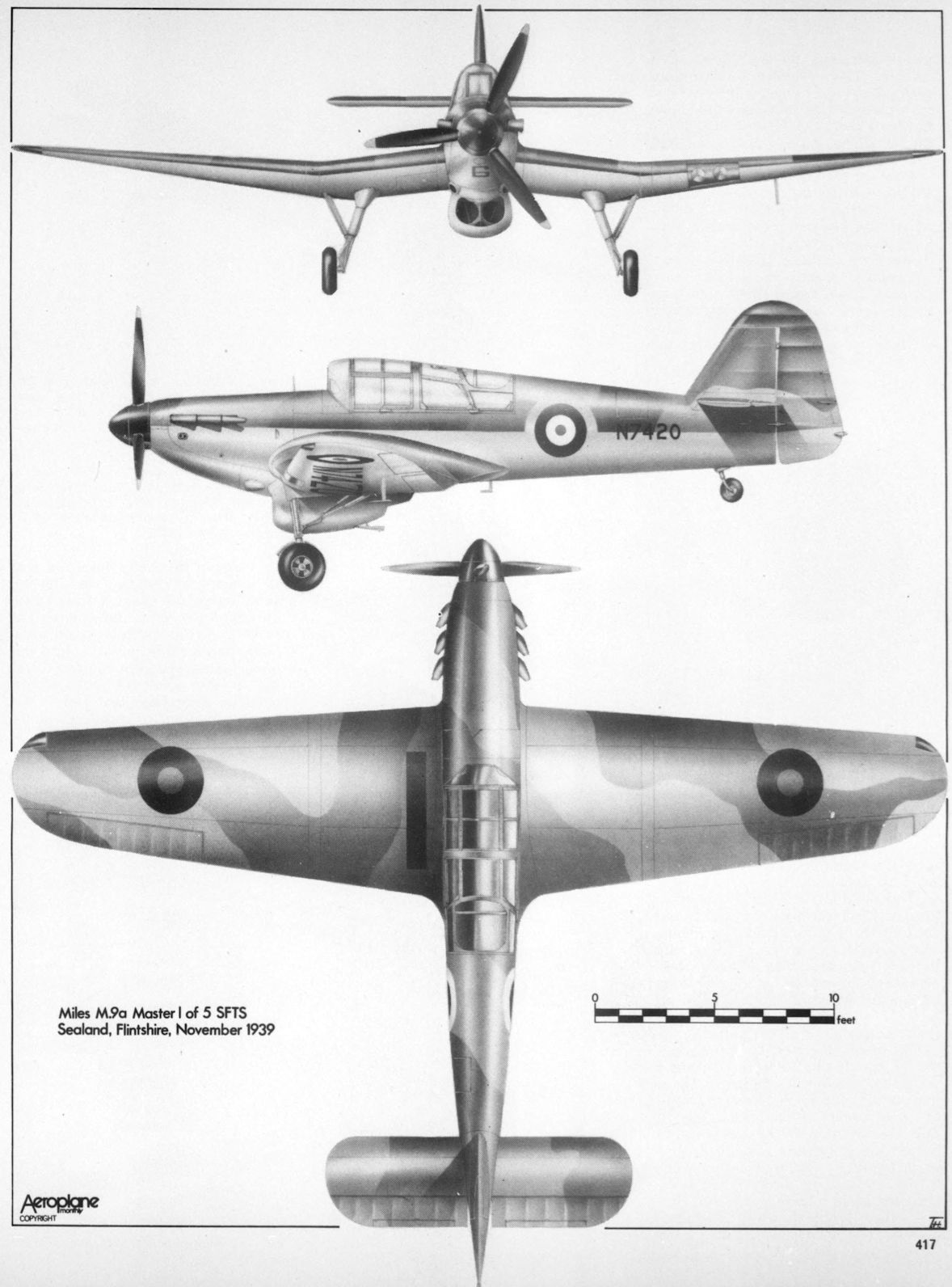
Aeroplane Monthly 1980-08 / P.Amos - Miles M.9A Master I /RAF Piston Trainers/ (10)
Miles M.9a Master I of 5 SFTS Sealand, Flintshire, November 1939
-

Air-Britain Aeromilitaria 1977-01
Miles Master I
-


Тип фотографий
- Все фото (106)
- Боковые проекции (1)
- Ч/б фото (65)
- Кабина (11)
- Модели, рисунки, схемы (29)