
 Wiki
Wiki 
Варианты
- Lockheed - Electra 10 - 1934 - США
- Lockheed - C-35 - 1936 - США
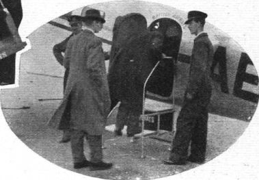
Lockheed 10 Electra
Можно сказать, что первым шагом "Lockheed" на пути к признанию в качестве ведущего разработчика и производителя гражданских самолетов стал Lockheed 10 Electra, рассчитанный на 9 пассажиров. Самолет Electra - цельнометаллический низкоплан с крылом консольного типа, двухкилевым оперением и убираемым шасси. На прототипе стояли моторы Pratt & Whitney Wasp Junior SB. Он выполнил первый полет 23 февраля 1934 года. Всего было построено 149 машин. Эксплуатация Electra началась в 1934 году, первой стала авиакомпания "Northwest Airlines". В конце 1930-х годов такие самолеты летали у восьми авиаперевозчиков США.
На момент вступления в США во Вторую мировую войну в эксплуатации оставалось несколько Electra, так как самолеты небольшой вместимости себя уже не оправдывали. Кроме США Electra поставлялись в Аргентину, Австралию, Канаду, Чили, Колумбию, Японию, Новую Зеландию, Польшу, Великобританию, Румынию, СССР, Венесуэлу и Югославию. Небольшое количество Electra приняло участие в гражданской войне в Испании, а с началом Второй мировой по нескольку машин поступили в ВВС Великобритании и Канады. Гражданские операторы продолжали эксплуатировать Electra в ограниченном масштабе и после окончания войны вплоть до конца 1960-х годов.
Варианты
Electra 10-A: основной серийный вариант с моторами Wasp Junior SB; построен 101
Electra 10-B: близок к Electra 10-A, но оснащен моторами Wright R-975-E3 Whirlwind мощностью по 440 л.с.; построено 18
Electra 10-C: вариант для авиакомпании "Pan American Airways" с моторами Wasp SC1 мощностью 450 л.с.; построено восемь
Electra 10-D: проект военного варианта; не строился
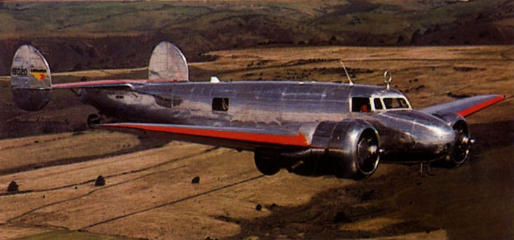
Electra 10-E: близок к Electra 10-A, но оснащен моторами Wasp S3H1 мощностью по 600 л.с.; построено 15; самый известный - NR16020, на нем 2 июля 1937 года при выполнении кругосветного перелета пропали без вести летчица Амелия Эрхарт и штурман Фред Нунэн
XR2O-1: один самолет для ВМС США, предназначенный для перевозки старших офицеров, оснащен моторами Pratt & Whitney R-985-48 мощностью по 450 л.с.
XR3O-1: один транспортно-санитарный самолет для Береговой охраны США, оснащен моторами Wright R-975-E3 мощностью по 440 л.с.
Y1C-36: обозначение в авиации Армии США трех Electra 10-A с моторами R-985-13 мощностью по 450 л.с., использовались как транспортные
C-36A (позже UC-36A): 15 самолетов Electra 10-A, применявшихся ВВС США в годы Второй мировой войны
C-36B (позже UC-36B): пять Electra 10-C для службы в ВВС США
C-36C (позже UC-36C): обозначение семи Electra 10-B, принятых на вооружение ВВС США
Y1C-37: один самолет, похожий на Y1C-36, закуплен Национальной гвардией США
ТАКТИКО-ТЕХНИЧЕСКИЕ ХАРАКТЕРИСТИКИ
Lockheed Electra 10-A
Тип: легкий транспортный самолет малой дальности
Силовая установка: два звездообразных мотора Pratt & Whitney Wasp Junior SB мощностью по 450 л. с. (336 кВт)
Летные характеристики: максимальная скорость 325 км/ч на высоте 1525 м; практический потолок 5915 м; дальность 1305 км
Масса: пустого 2927 кг; максимальная взлетная 4672 кг
Размеры: размах крыла 16,76 м; длина 11,76 м; высота 3,07 м; площадь крыла 42,59 м2
Описание:
- Lockheed 10 Electra
- Flight, July 1933
THE LOCKHEED "ELECTRA” - Flight, January 1934
The Lockheed "Electra" - Flight, April 1937
SIMPLEXITY ITSELF
Фотографии

-

Мировая Авиация 174
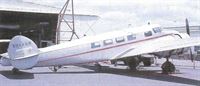
Регистрационный номер: NC233Y [3], X233Y [3] Ранние Electra, поставленные компании "Northwest Airlines", отличались наклоненным верхней частью вперед лобовым остеклением кабины. Начиная с пятого самолета, монтировалось более привычное сейчас лобовое остекление.

-

-

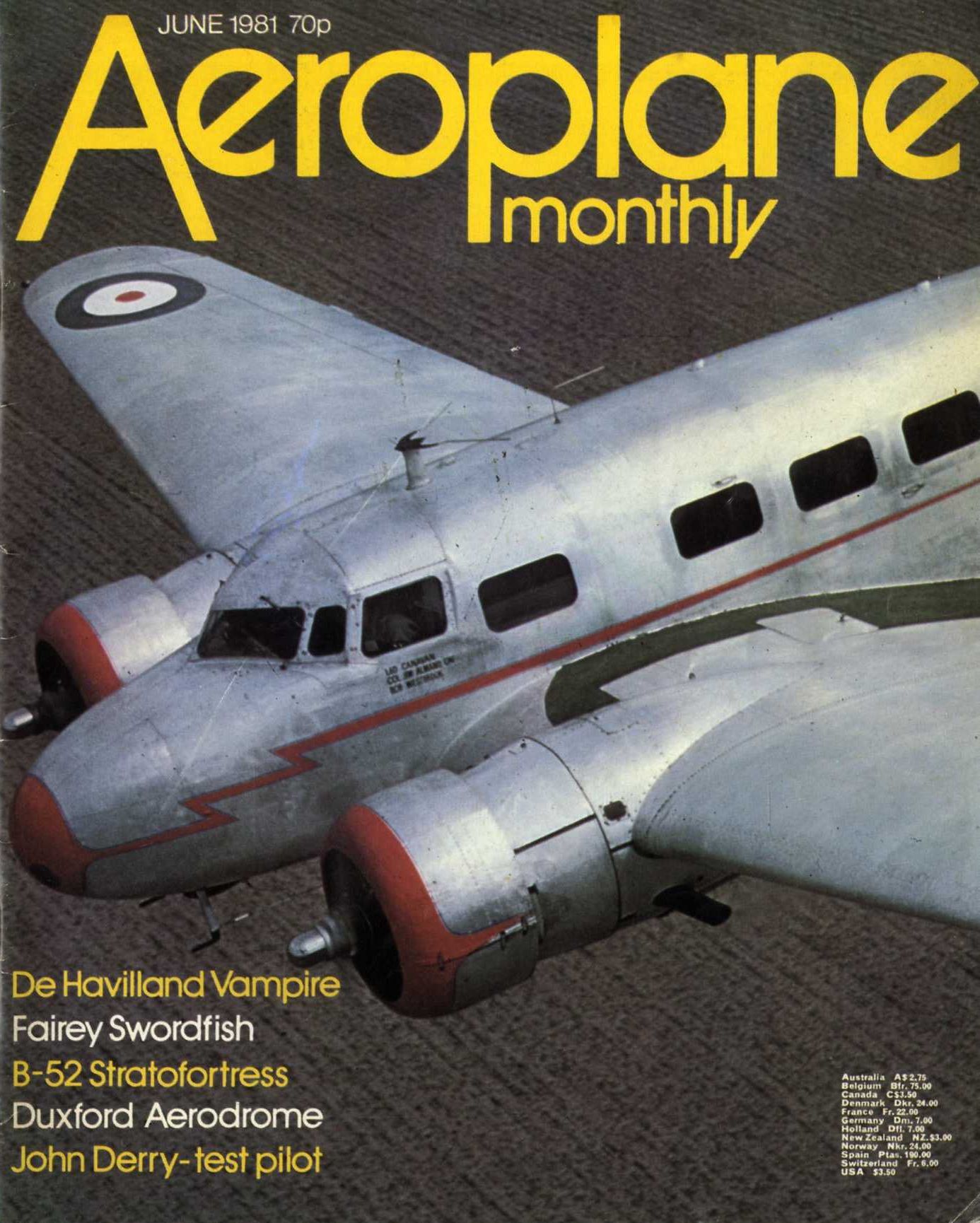
Aeroplane Monthly 1981-06
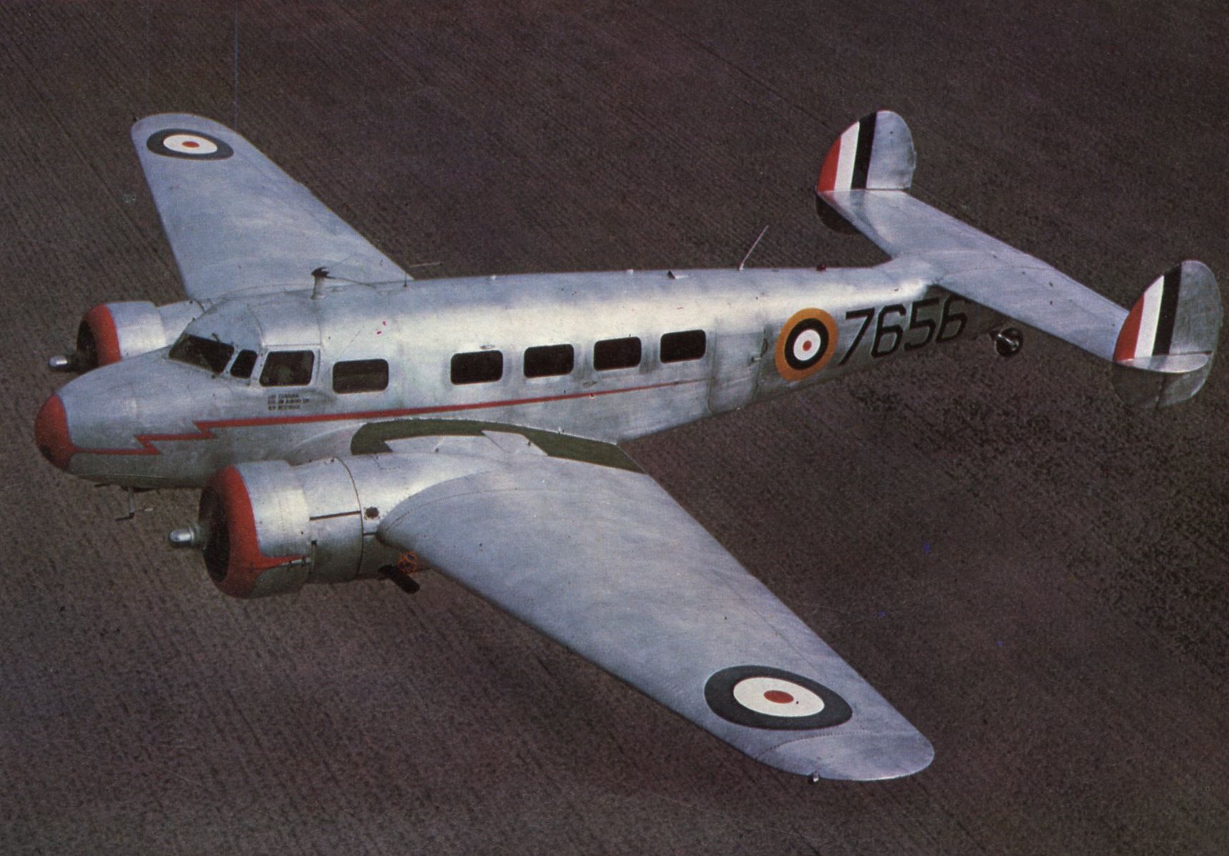
The RCAF Lockheed 10, 7656
-
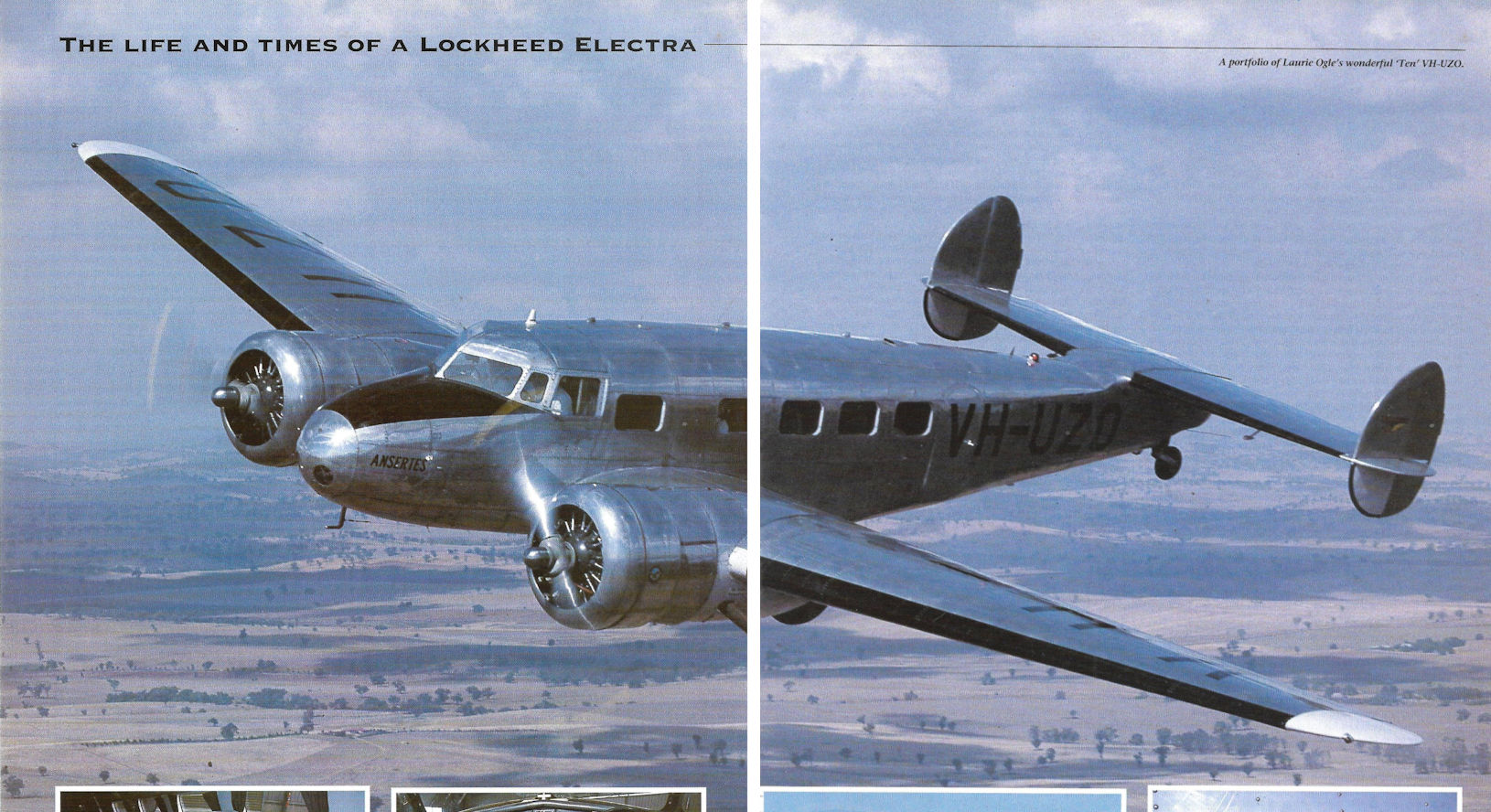
Air Enthusiast 2001-07 / C.Justo - Ten Out of Ten
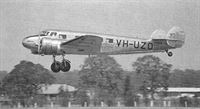
Регистрационный номер: VH-UZO [7], G-AFTL [7] Laurie Ogle's wonderful 'Ten' VH-UZO
-
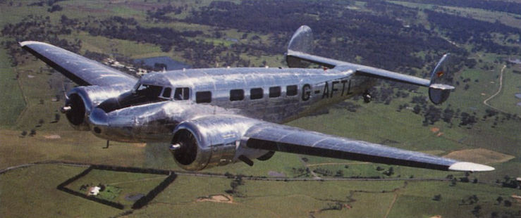
Aeroplane Monthly 2000-04 / M.Oakey, T.Harmsworth - News
Регистрационный номер: G-AFTL [7], VH-UZO [7] Lockheed 10 VH-UZO, marked as Lockheed 12 G-AFTL, airborne near Sydney.
-

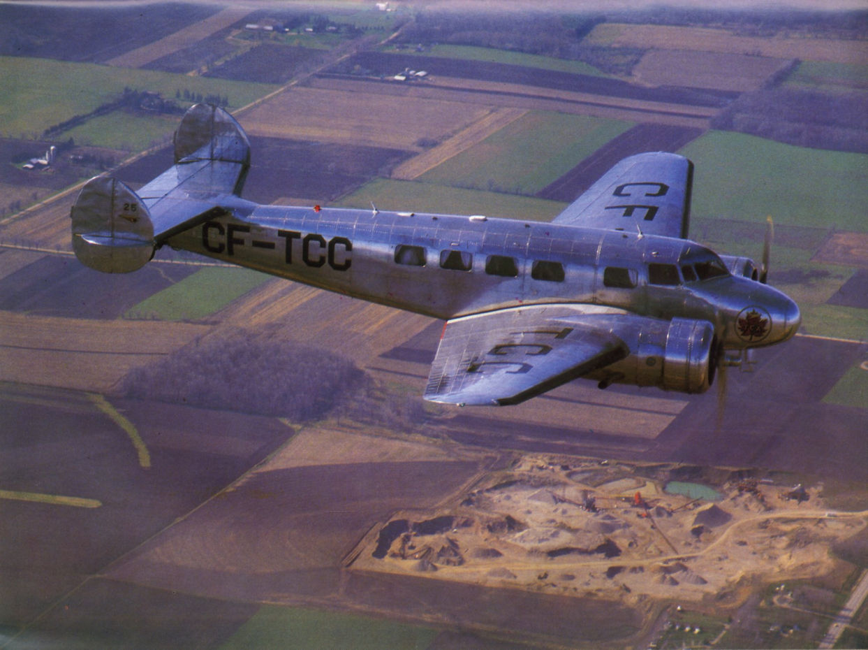
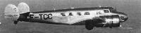
Aeroplane Monthly 1986-07 / Lockheed 10A Electra CF-TCC /Preservation Profile/
Регистрационный номер: CF-TCC [5] Lockheed Electra CF-TCC photographed by CHUCK SLOAT on April 23, 1986, en route from London, Ontario to Toronto
-
Aeroplane Monthly 1997-06 / M.Oakey - Vintage news
Linda Finch and Laird “Lad” Doctor (the first of her eight navigators) flying her Lockheed Electra along the California coastline near Half Moon Bay on the first leg of her world flight on March 17, 1997.
-
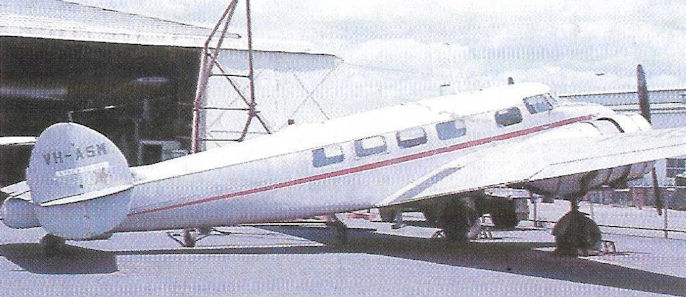
Air Enthusiast 2001-07 / C.Justo - Ten Out of Ten
Регистрационный номер: VH-ASM VH-ASM at Bankstown, December 1974, eight years after her grounding
-
Air Enthusiast 2001-07 / C.Justo - Ten Out of Ten
Регистрационный номер: VH-UZO [7], G-AFTL [7] Gleaming L.10A VH-UZO proudly owned by Sydney-based businessman Laurie Ogle
-
Air Enthusiast 2001-07 / C.Justo - Ten Out of Ten
Регистрационный номер: VH-UZO [7], G-AFTL [7] -
Air Enthusiast 2001-07 / C.Justo - Ten Out of Ten
Регистрационный номер: VH-UZO [7], G-AFTL [7]


-

Aeroplane Monthly 2000-01 / P.Jarrett - Landmarks in the sky /Epoch-making aircraft/
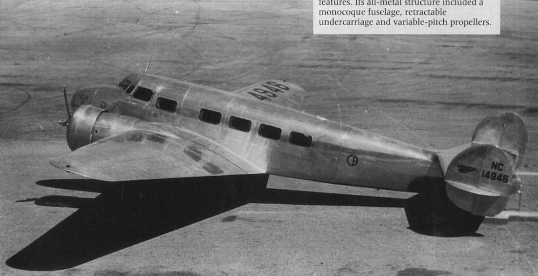
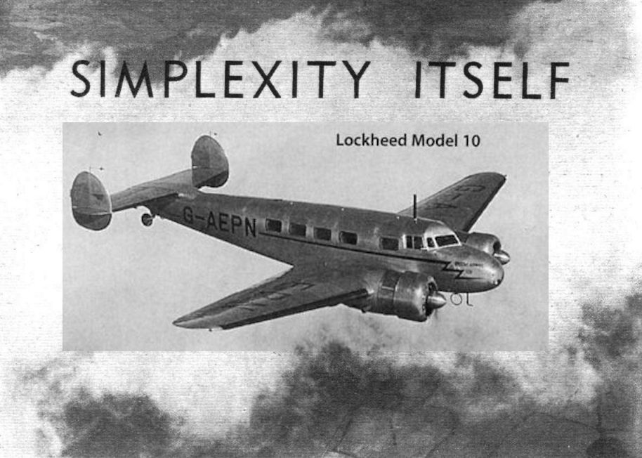
Регистрационный номер: NC14946 Lockheed's handsome Model 10 Electra was one of several advanced monoplane transports to come from the USA in the mid-1950s and put the European aircraft industry to shame with their advanced features. Its all-metal structure included a monocoque fuselage, retractable undercarriage and variable-pitch propellers.
-

Flight 1934-05 / Flight
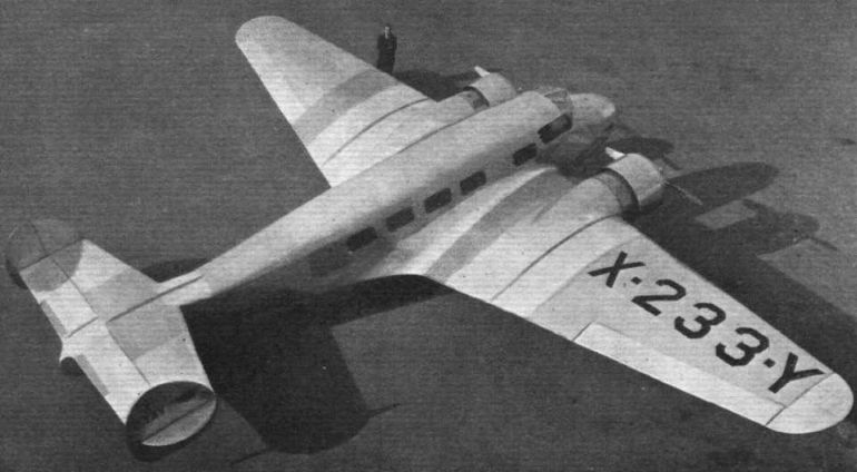
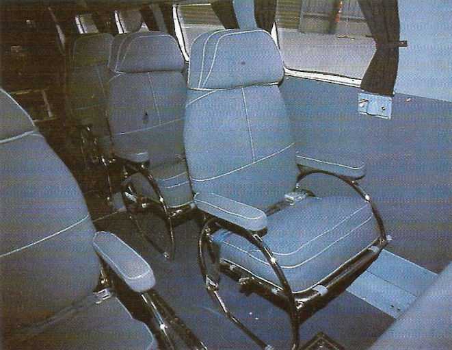
Регистрационный номер: X233Y [3], NC233Y [3] A SPEEDY EXAMPLE: The Lockheed "Electra," operated by certain American airlines, has a top speed of about 220 m.p.h. Although, compared with other types, the accommodation is somewhat cramped, the cabin is by no means uncomfortable.
-

Flight 1934-03 / Flight
Регистрационный номер: X233Y [3], NC233Y [3] IN FULL FLIGHT: The Lockheed "Electra" makes its maiden flight at Burbank, California, on February 23.
-

Flight 1939-04 / Flight
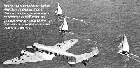
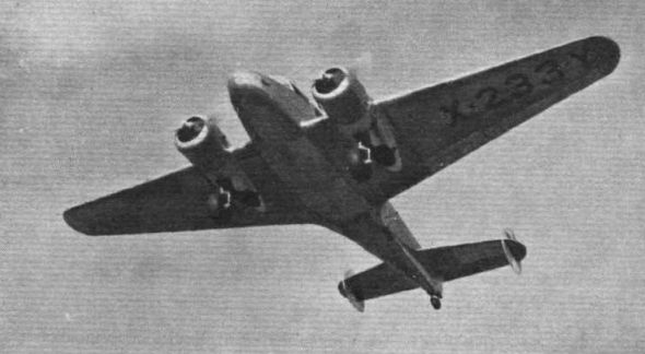
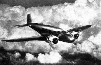
COMING IN: The machine shown about to land with flaps and wheels lowered is a Lockheed Electra
-

Air Enthusiast 1994-09 / A.Wood - Airline at War
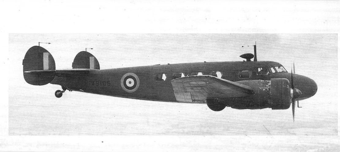
Регистрационный номер: W9106 [2], G-AEPO [2] Former British Airways Electra L.10A G-AEPO was impressed for service with the RAF as W9106 in April 1940. It served with 24 Squadron at Hendon until 1942. It was dismantled for spares recovery at Hendon in June 1942.
Lockheed 10 Electra G-AEPO of British Airways is seen after impressment as W9106, 4.40. It was dismantled at Hendon 13.5.42 and struck off charge on 1.7.42. It was noted in the Log, for different reasons, on 8.3.38 and 9.3.38. -

Air Enthusiast 1994-09 / A.Wood - Airline at War
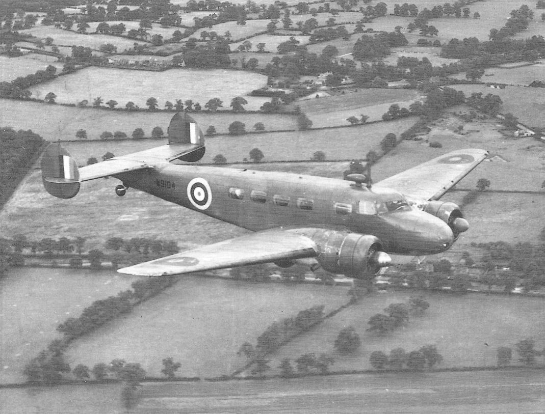
Регистрационный номер: W9104 [6], G-AFEB [6] Another view of Lockheed 10A Electra W9104 of 24 Squadron.
-

Air Enthusiast 1994-09 / A.Wood - Airline at War
Регистрационный номер: W9104 [6], G-AFEB [6] Lockheed 10A Electra W9104 of 24 Squadron. It had previously served with British Airways as G-AFEB.
-
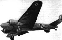
Air Pictorial 1957-11 / B.Robertson - U.S. Aircraft in the British Services 1914-1955 (9)
Регистрационный номер: W9104 [6], G-AFEB [6] The Lockheed Electra W9104, previously used by British Airways as G-AEPN;
-

-

Aeroplane Monthly 1989-02 / R.Nesbit - What did happen to Amelia Earhart? (2)
Amelia's Electra over San Francisco Bay.
-

Aeroplane Monthly 1989-01 / R.Nesbit - What did happen to Amelia Earhart? (1)
SPRING - AT 9,000 ft: A sunny impression, by Flight's photographer, of the first of British Airways' new Lockheed Electras flying above the clouds near Southampton, where the machines are being erected. Mr. Marshall Headle, Lockheed's chief test pilot, is in charge.
-

Flight 1938-01 / Flight
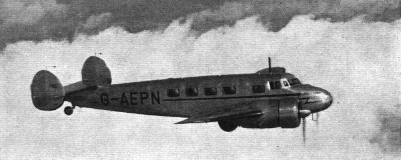
Регистрационный номер: G-AEPN [10], W9105 [10] One of British Airways' Lockheed Electras.
-

-

Air Enthusiast 2000-11 / G.Warner - Founding Fathers (2)
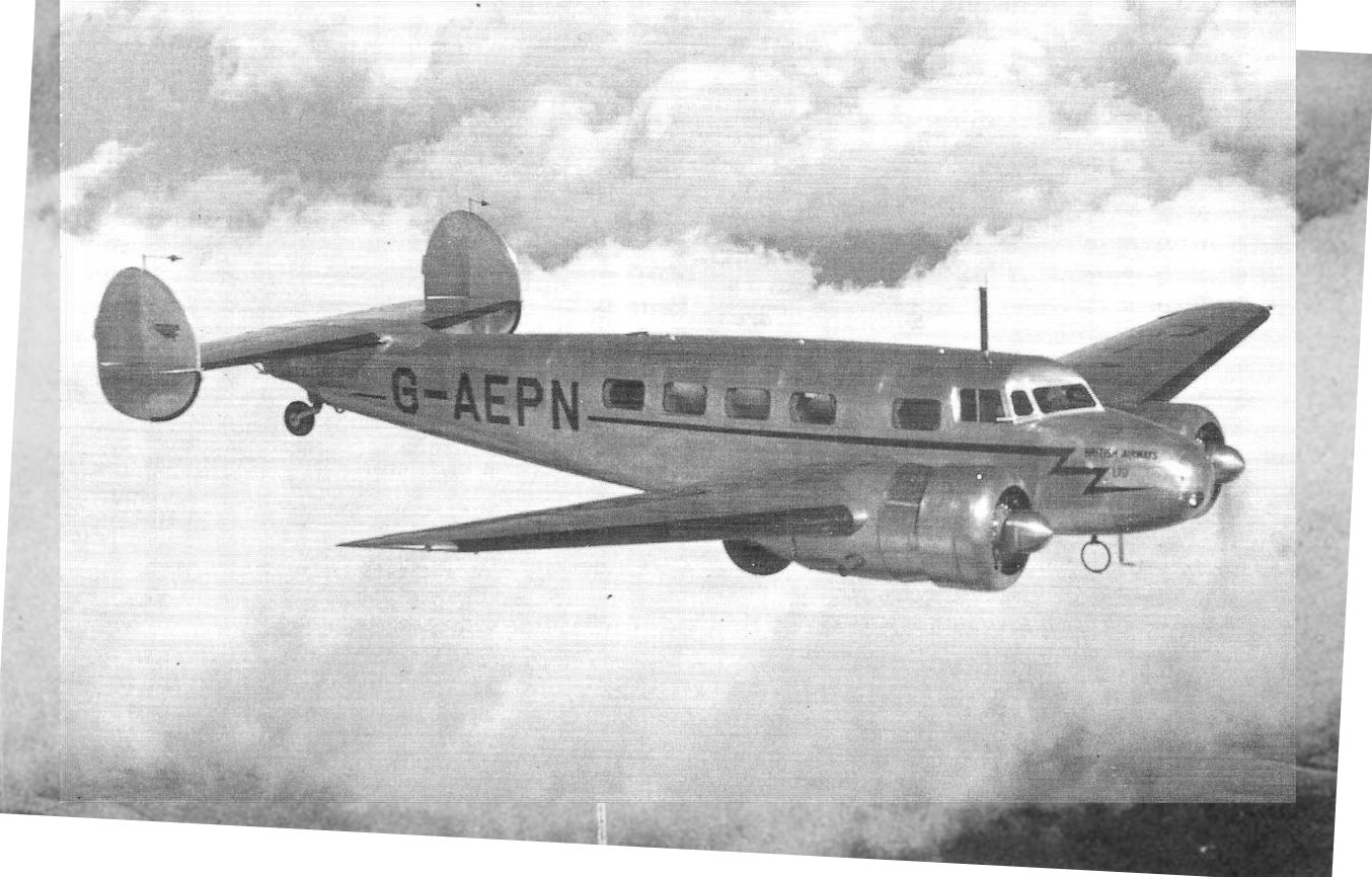
Регистрационный номер: G-AEPN [10], W9105 [10] One of five British Airways Lockheed Model 10A Electras, G-AEPN. It was impressed as W9105.
Lockheed 10A G-AEPN was commissioned in April 1937. During the summer season Electras made six return flights a day each on the Croydon - Le Bourget run. -

Flight 1937-04 / Flight Advertisements
Регистрационный номер: G-AEPN [10], W9105 [10] В конце 1930-х годов "British Airways" заказала семь самолетов Model 10-A. Они использовались на линиях в Европе, в том числе и в Скандинавии, где часто стояла неблагоприятная погода.
G-AEPN Lockheed 10A Electra of British Airways operated a 90 minute service from Croydon to Le Bourget and also participated in the Viking Mail Service to Stockholm, leaving Croydon at 6 pm with calls at Hamburg, Copenhagen and Malmo. It featured in a take-off incident on 10.8.37. -

Flight 1937-12 / Flight
Регистрационный номер: G-AEPN [10], W9105 [10] -
Jane's All the World Aircraft 1938 / 03 - All the world's aeroplanes
Регистрационный номер: G-AEPN [10], W9105 [10] The Lockheed "Electra" Ten-passenger Commercial Monoplane (two 450 h.p. Pratt & Whitney "Wasp-Junior" engines).
-

-

Aeroplane Monthly 1974-11 / P.Moss - British Airways (2)
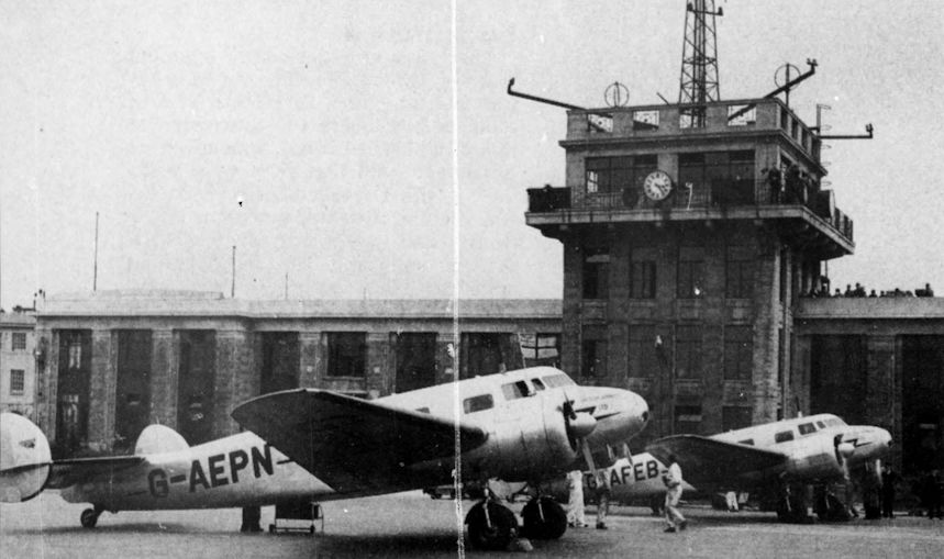
Регистрационный номер: G-AEPN [10], G-AFEB [6], W9104 [6], W9105 [10] Lockheed 10As G-AEPN and G-AFEB awaiting passengers at Croydon at 3.23 p.m. on April 24, 1938.
-

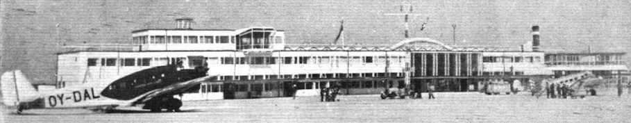
Flight 1939-06 / Flight
Kastrup Airport, outside Copenhagen. The new buildings have just been opened. A British Airways Electra is on the right.
Другие самолёты на фотографии: Junkers Ju.52/3m - Германия - 1931
-

Aeroplane Monthly 1989-02 / Skywriters
A Lockheed 10 Electra, Bloch 221 and an HP.42 diverted to RAF Kenley during bad weather in 1938.
Другие самолёты на фотографии: Bloch MB.220 - Франция - 1936Handley Page H.P.42 / H.P.45 - Великобритания - 1930
-

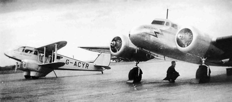
Air-Britain Archive 1996-04 / Croydon Watch Log 1937-8 (7)
Регистрационный номер: G-AEPN [10], W9105 [10] British Airways' Lockheed 10A G-AEPN running up with Olley's Dragon Rapide G-ACTR behind. Both were mentioned in separate incidents involving other movements on 20.4.38.
Другие самолёты на фотографии: De Havilland Dragon Rapide / Dominie / D.H.89 - Великобритания - 1934
-

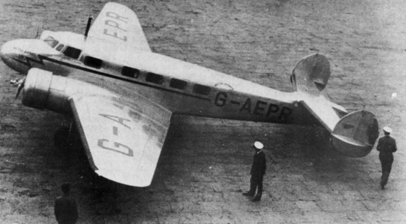
Aeroplane Monthly 1974-11 / P.Moss - British Airways (2)
Регистрационный номер: G-AEPR [2] Another of British Airways' Electras, G-AEPR, about to depart Croydon on the high-frequency, 90-minute Paris service in July 1937.
-

Aeroplane Monthly 1974-11 / P.Moss - British Airways (2)
Регистрационный номер: G-AEPO [2], W9106 [2] -

Flight 1938-04 / Flight
Регистрационный номер: G-AFEB [6], W9104 [6] London’s Terminal : British Airways, imperial Airways and K.L.M. on the tarmac at Croydon.
Другие самолёты на фотографии: Douglas DC-1 / DC-2 / C-32 / C-39 - США - 1933Short Scylla / L.17 - Великобритания - 1934
-

-

Flight 1938-07 / Flight Advertisements
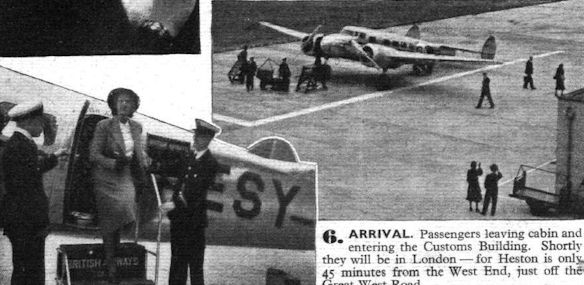
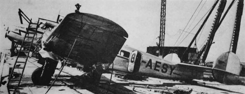
Регистрационный номер: G-AESY [2] -
Air-Britain Archive 1983-04 / Impressment Review (15)
Регистрационный номер: G-AESY [2] British Airways Lockheed Electra G-AESY after salvage. It crashed off the Danish coast on 15.9.39 and was written off due to salt water corrosion after being returned to its owners.
-
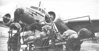
Air Enthusiast 1994-09 / A.Wood - Airline at War
Регистрационный номер: G-AEPN [10], W9105 [10] Loading mail into G-AEPN in classic British weather!
-

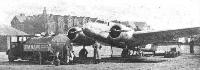
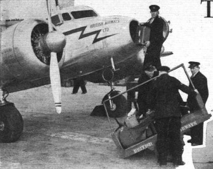
Air-Britain Archive 1997-03 / Croydon Watch Log 1937-8 (10)
Loading newspapers and freight into a British Airways Lockheed 10A in front of Croydon's famous terminal building.
-

-

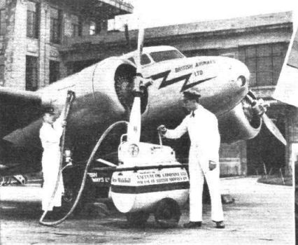
Flight 1937-05 / Flight
CLEAN AND SMART: A British Airways' Lockheed Electra being filled up with engine oil from one of the Vacuum Company's new portable 50-gallon dispensing units. A rotary pump delivers oil, via a Victory meter calibrated in pints, at 2-3 galls./min. There are several ingenious features.
-

Air Enthusiast 2001-07 / C.Justo - Ten Out of Ten
British Airways (the first incarnation!) operated five L.10As from 1937.
-

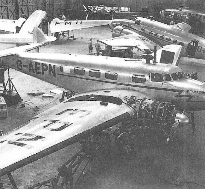
Air Enthusiast 1994-09 / A.Wood - Airline at War
Регистрационный номер: G-AEPN [10], W9105 [10] Electra G-AEPN undergoing maintenance in the British Airways hangar at Heston. In the background are four Lockheed 14-WF62s, including G-AFMO which was destroyed in a crash-landing at Heston on January 15,1940.
Другие самолёты на фотографии: Lockheed Super Electra 14 - США - 1937
-

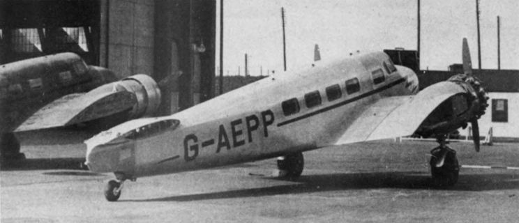
Aeroplane Monthly 1974-11 / P.Moss - British Airways (2)
Регистрационный номер: G-AEPP Lockheed 10A Electra G-AEPP and a sister ship being erected at Eastleigh after shipment from Burbank, USA.
-

Aeroplane Monthly 1988-04 / Personal album. Civil
Регистрационный номер: G-AFEB [6], W9104 [6] Lockheed 10E G-AFEB was registered in the UK in March 1938 to British Airways and used on the Paris and Stockholm services. It was later used on the National Air Communications emergency airlift between Heston, Shoreham and Le Bourget, for which it was camouflaged and given RAF roundels. In April 1940 ’EB was impressed and given the RAF serial number W9104. It flew with 24 Sqn until damaged beyond repair following a landing at Clifton on October 12, 1941. The ten-passenger Model 10E was powered by two 550 h.p. Wasp S3H1 radials and cruised at around 200 m.p.h. at 10,000ft.
-
Flight 1937-05 / Flight
TWO-WAY SPIRIT: Merrill's Electra being refuelled on Southport Sands in readiness for its return Atlantic flight.
-

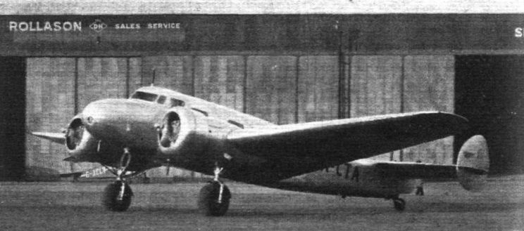
Flight 1937-01 / Flight
The Flight photograph is of a Lockheed Electra, the agents for which are Rollason Aircraft Services.
-

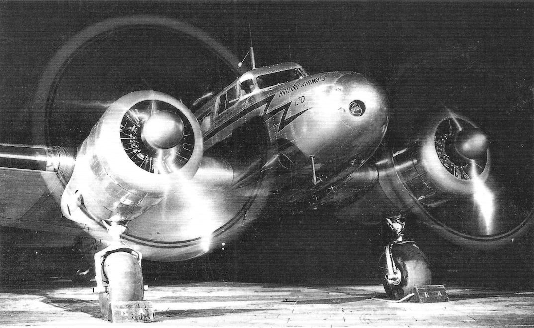
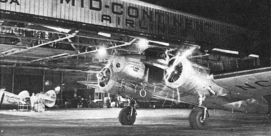
Flight 1939-05 / Flight
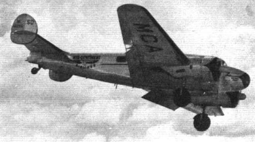
PHANTASMAGORIA: A Mid-Continent Airlines Lockheed Electra is run up preparatory to a night flight from the Company's base at Kansas City.
-

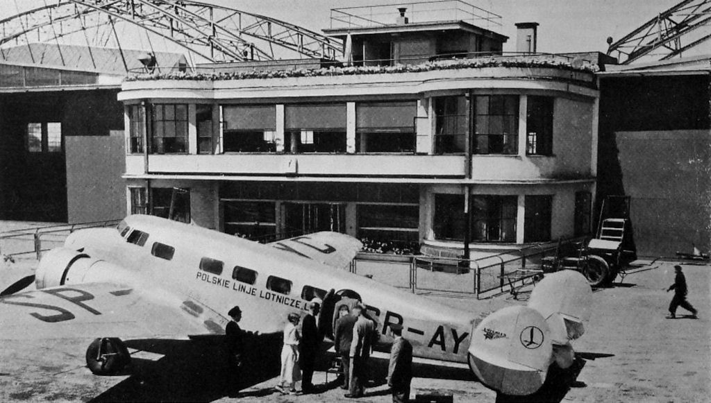
Jane's All the World Aircraft 1938 / 01 - The progress of the world in civil aviation during the year 1937-38
Регистрационный номер: SP-AYC POLAND'S AIRLINE. - Lockheed "Electra" of L.O.T. Polskie at the Warsaw (Okecie) Airport.
-

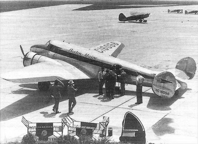
Air Enthusiast 2001-07 / C.Justo - Ten Out of Ten
Регистрационный номер: NC16056 Lockheed 10A NC16056 of Boston-Maine Airlines
-
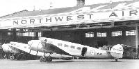
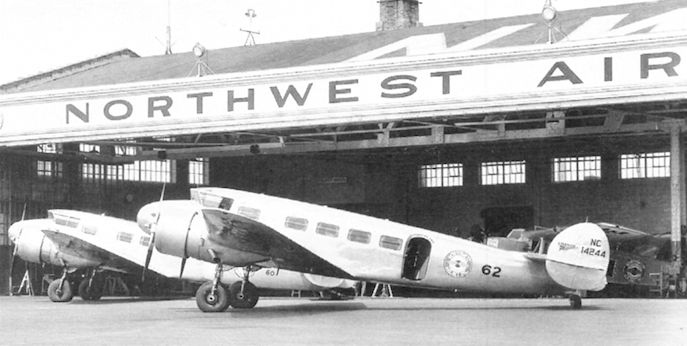
Мировая Авиация 162
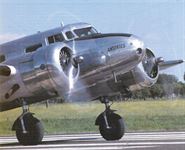
Регистрационный номер: NC14244 У этой пары Model 10 хорошо виден характерный ветровой козырек с обратным наклоном. Компания "Northwest" стала первым оператором машины, получившим самолеты в 1934 году.
-

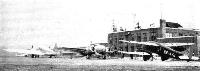
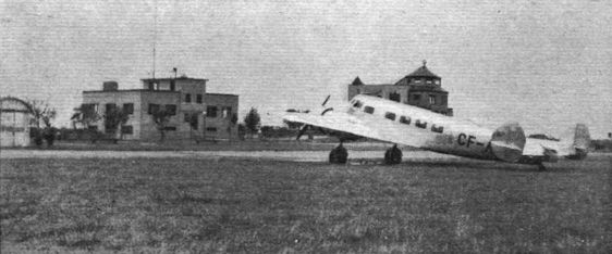
Flight 1938-01 / Flight
CANADIAN TERMINUS: Sea Island Airport, Vancouver, B.C., where the trans-Canada service has its western terminus. The administration building is on the right and the new radio station is on the left. In the foreground is Canadian Airways’ first Lockheed Electra used on the Vancouver-Seattle service.
-
Flight 1936-07 / Flight
UBIQUITOUS: A D.H. Dragon Rapide, used by Canadian Airways on the daily Seattle-Vancouver service, parked in front of the administration building, Boeing Field, Seattle, Wash. An interesting feature of this Rapide is the increased fin area necessary when floats are fitted. The other machines will be recognised as a Lockheed Electra 10A of Northwest Airlines and a Boeing 247D of United Air Lines.
Другие самолёты на фотографии: Boeing Model 247 - США - 1933De Havilland Dragon Rapide / Dominie / D.H.89 - Великобритания - 1934
-

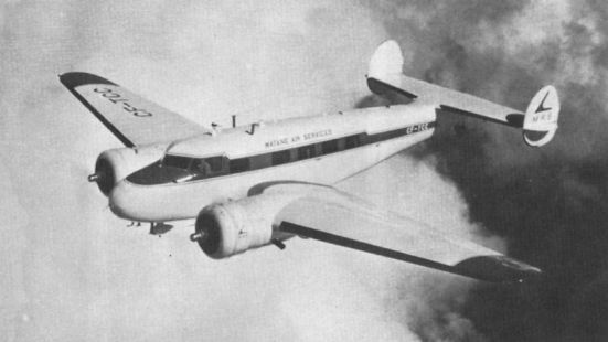
Aeroplane Monthly 1986-07 / Lockheed 10A Electra CF-TCC /Preservation Profile/
Регистрационный номер: CF-TCC [5] CF-TCC in Matane Air Service livery.
-
Air International 1987-07
Регистрационный номер: CF-TCC [5] To mark the 50th anniversary of Air Canada, the airline's first aircraft, this Lockheed Model 10A Electra, was restored and flown across the continent during 1986.
-

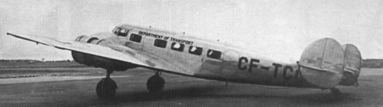
Aeroplane Monthly 1986-07 / Lockheed 10A Electra CF-TCC /Preservation Profile/
Регистрационный номер: CF-TCC [5] Lockheed 10A number 1116 shortly after acquisition by DOT in 1939. The picture was taken at Uplands Airport on May 8, 1940.
-

Flight 1936-09 / Flight
Регистрационный номер: CF-AZY Canadian Airways' latest acquisition, a Lockheed Electra 10.A, which cruises at 190 m.p.h. with ten passengers and freight.
-

Air-Britain Archive 1997-01 / Extracts
Регистрационный номер: USSR-N214, NR16059 THE RECORD HOLDERS, 1949. Point to Point [Pilot/crew]
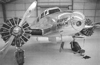
* New York-London - 9/10.5.37; Lockheed Electra NR16059 c/n 1065; 20hr 29min [272.345km/hr] HT Merill/JS Lambie. H.T.(Dick) Merrill and J.S.(Jack) Lambie flew Lockheed 10E Electra c/n 1065 NC16059 'Daily Express' to bring London within 20 hr 29 min of New York. The return flight of 24 hr 22 min was made carrying newsreels of the coronation of King George VI. The engines of the 10E were two 450 hp Pratt & Whitney S3H1 9-cyl radials instead of the 400 hp P & W SB 9-cyl radials fitted to the 10A. NC16059 was afterwards used in the unsuccessful search for the missing Russian polar flyers Levanevsky and Levchenko and ended its career in Russia. Wing span 16.76 m (55 ft), Loaded weight 4673 kg (10,500 lb).
Merrill Lambie's record-breaking Lockheed 10E NR16059 was afterwards sold to Russia and is seen before departure with registration N-214 on the rudder and USSR on the wing and fuselage. -

Air-Britain Archive 1999-04 / Extracts
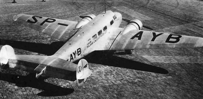
Регистрационный номер: SP-AYB Lockheed 10A Electra SP-AYB c/n 1046 of LOT which crashed in central Greece on 1.12.36.
Het Vliegveld: 01.12.36: Polish airliner en route Warsaw - Saloniki hits mountain in fog 20 km from Athens, pilot killed, 4 passengers injured.
Het Vliegveld: 01.12.36: Polish airliner was LOT Lockheed 10A Electra SP-AYB c/n 1046 en route Warsaw - Saloniki - Athens. Hit mountain in fog near Malakasi, 20 km from Athens, pilot Jozef Barziel (Bergel?) killed, 4(5?) passengers and 1 crew injured, 1 crew unhurt. Pilot error blamed. -

Aviation Historian 30 / P.Vabre - From Flying to Spying (1)
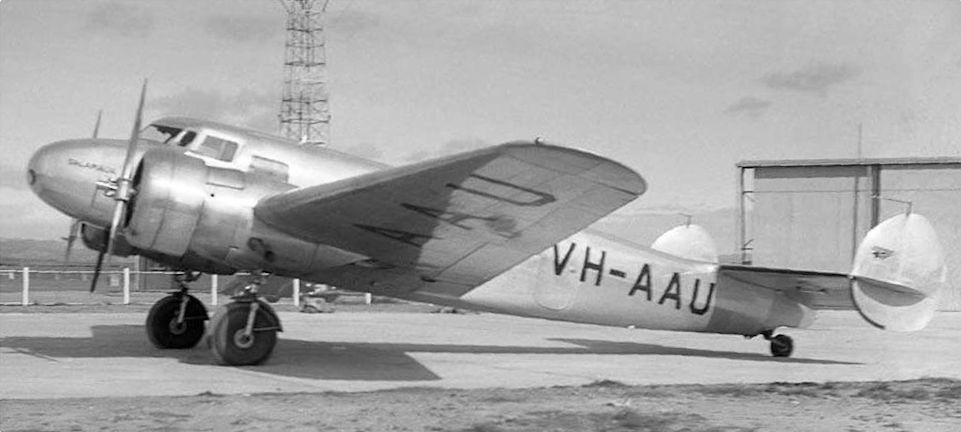
Регистрационный номер: VH-AAU Lacking a state-of-the-art transport aircraft of its own, in the late 1930s Australia’s Civil Aviation Branch chartered Guinea Airways’ Lockheed 10A Electra VH-AAU Salamaua for several tasks, including the flight-testing of Lorenz radio navigation beacons and the July 1939 survey flight to Dili. It is seen here at Adelaide-Parafield.
-

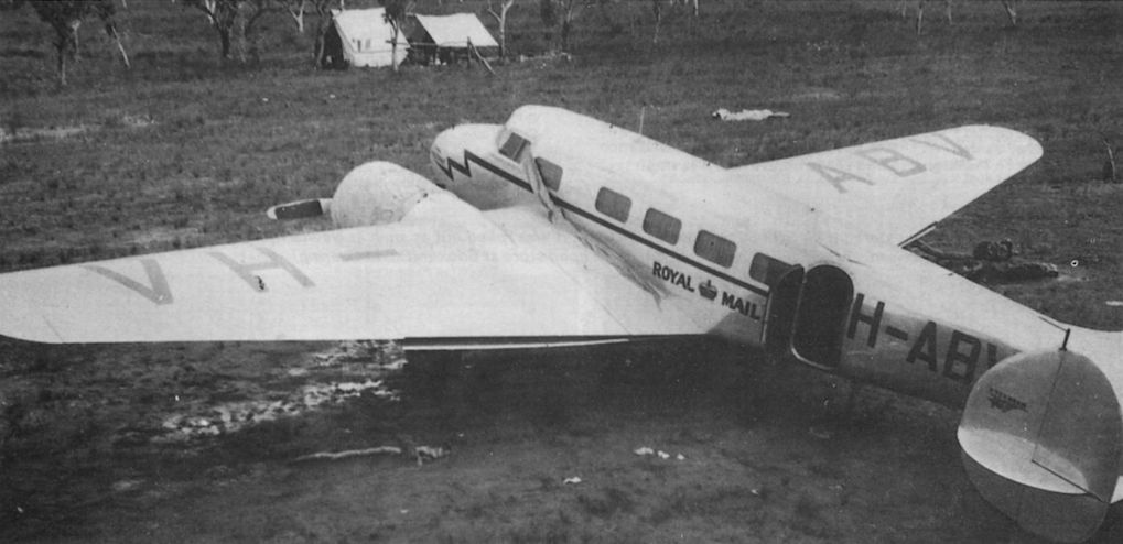
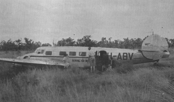
Air Pictorial 1991-10 / J.Grant - Salvage... bush fashion
Регистрационный номер: VH-ABV [3], VH-MMD [3] The Electra waiting on the airstrip for it to dry out sufficiently to allow a take off to be attempted
-

Flight 1938-12 / Flight
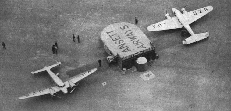
Регистрационный номер: VH-UZN, VH-UZP [2] SIMPLIFICATION: In Australia it is usual for the airline companies to put up their own airport buildings. This is a somewhat unique example of such a building at Mildura airport, with two of Ansett Airways’ Lockheeds beside it. The position of this little Ansett building, away from the aerodrome boundary, should simplify the work of loading and unloading.
-
Jane's All the World Aircraft 1938 / 01 - The progress of the world in civil aviation during the year 1937-38
AN UP-COUNTRY JUNCTION. - Daly Waters, where a D.H. "Dragon" of MacRobertson-Miller Airways, West Coats service has met a Lockheed "Electra" of Guinea Airways' trans-continental line from Adelaide to Darwin.
Другие самолёты на фотографии: De Havilland Dragon / D.H.84 - Великобритания - 1932
-
Air Enthusiast 2001-07 / C.Justo - Ten Out of Ten
Регистрационный номер: VH-UZO [7], G-AFTL [7] The newly-restored VH-UZO making its public debut at Richmond, 1991.
-

Flight 1938-09 / Flight
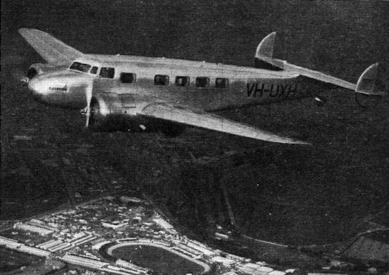
Регистрационный номер: VH-UXH A Lockheed Electra 10A of Guinea Airways in the vicinity of Flemington Racecourse.
-

Jane's All the World Aircraft 1938 / 01 - The progress of the world in civil aviation during the year 1937-38
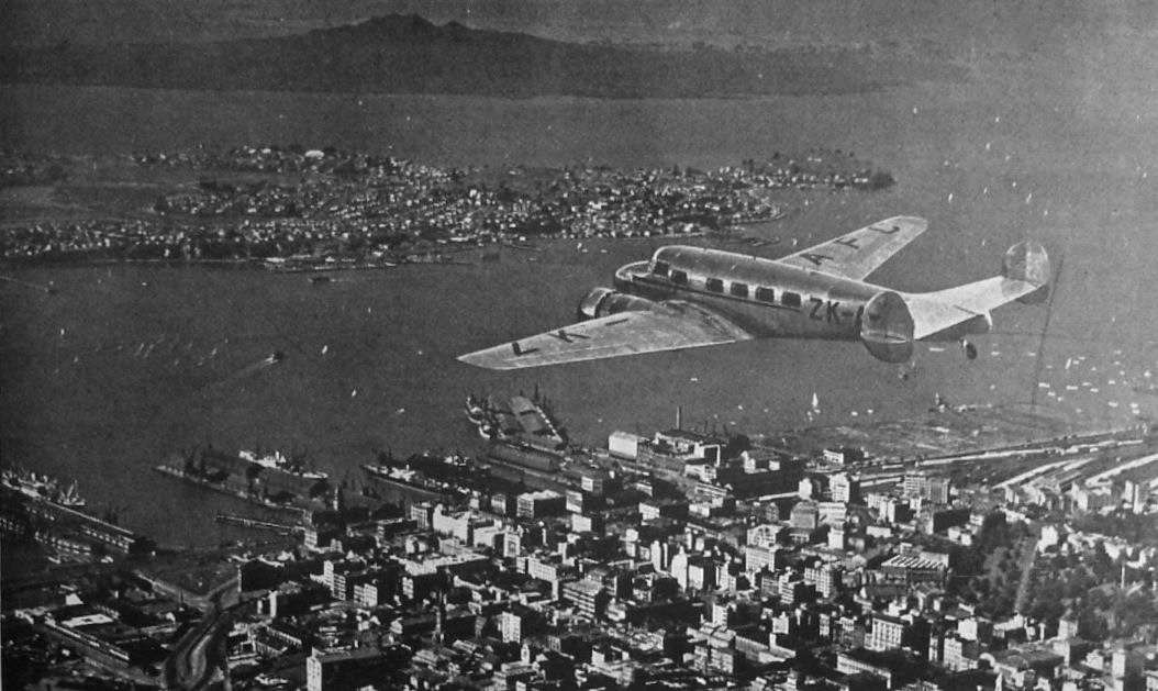
Регистрационный номер: ZK-AFC NEW ZEALAND'S TERMINUS. - Auckland, which is the Northern extremity of the airline system and is to be its junction with the Pan American service to Honolulu. A Lockheed "Electra" of Union Airways is seen over the city.
Union Airways' first Electra ZK-AFC which was unfortunately short-lived. -
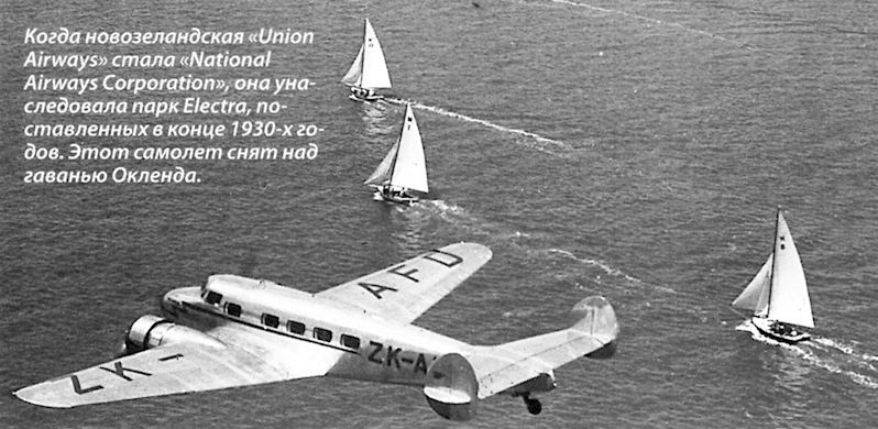
Мировая Авиация 162
Регистрационный номер: ZK-AFD [5] Когда новозеландская "Union Airways" стала "National Airways Corporation", она унаследовала парк Electra, поставленных в конце 1930-х годов. Этот самолет снят над гаванью Окленда.
-

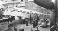
Air-Britain Archive 1982-02 / J.Geelen, R.Deerness - New Zealand (ZK-) /Complete Civil Registers/ (3)
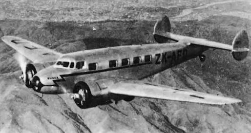
Регистрационный номер: ZK-AFD [5] By way of contrast ZK-AFD, the first of the Electras to fly in NZ, still exists as a museum exhibit in Auckland.
-
Air Enthusiast 2001-07 / C.Justo - Ten Out of Ten
Регистрационный номер: ZK-AFD [5], N10Y [3], NC21735 [3], ZK-BUT [3] L.10A 'ZK-AFD' (really ZK-BUT) is displayed at Auckland, New Zealand.
-
Air-Britain Archive 1983-04 / J.Geelen, R.Deerness - New Zealand (ZK-) /Complete Civil Registers/ (3)
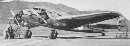
Регистрационный номер: ZK-ALI The highly-polished NZNAC Electra ZK-ALI "Koweka" at Rongotai, Wellington.
-

Air Pictorial 1958-07
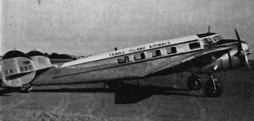
Регистрационный номер: ZK-BUT [3], N10Y [3], NC21735 [3], ZK-AFD [5] Lockheed 10A Electra ZK-BUT (c/n. 1138 ex NC21735 ex N10Y) has been newly commissioned by Trans Island Airways.
-

Air-Britain Archive 1991-02 / J.Geelen, R.Deerness - New Zealand (ZK-) /Complete Civil Registers/ (3)
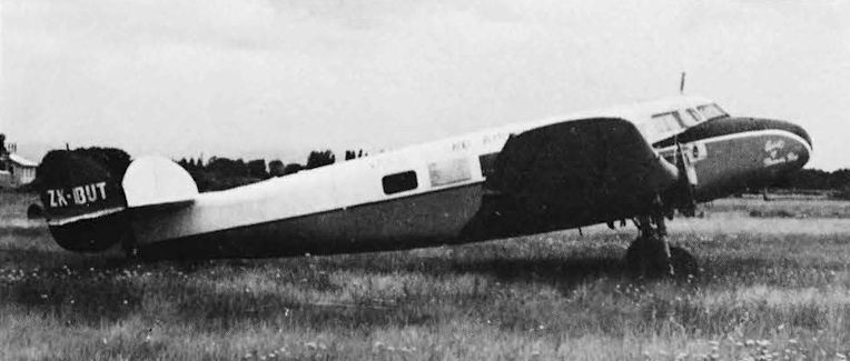
Регистрационный номер: ZK-BUT [3], N10Y [3], NC21735 [3], ZK-AFD [5] Trans-Island Airways L.10E Electra ZK-BUT "Spirit of Tasman Bay" was fortunate to survive from this somewhat dilapidated condition and is now exhibited at Auckland as ZK-AFD.
-
Air Pictorial 1957-10 / Air Pictorial's photo-review
"HEAP BIG SMOKE". A smartly-painted, pre-war Lockheed Model 10E Electra photographed recently at San Fernando, California by Warren M. Bodie of Van Nuys. The 550-h.p. P. & W Wasp S3H1 radials are enclosed in military-surplus BT-13 cowlings. The Electra can seat twelve and has a max. speed in excess of 210 m.p.h. Note the Red Indian "fire-maker" insigne on the fin and rudder.
-

Aeroplane Monthly 1986-07 / Lockheed 10A Electra CF-TCC /Preservation Profile/
Регистрационный номер: CF-TCC [5] The Lockheed 10 owned by the Confederate Air Force, in RCAF scheme in the 1970s.
During the war the RCAF used a number of Lockheed Model 10-As and 10-Bs for communications and flying instruction. The example seen here, painted in RCAF markings, is a 10-A operated in recent years by the Confederate Air Force. -

Aeroplane Monthly 1989-01 / R.Nesbit - What did happen to Amelia Earhart? (1)
Регистрационный номер: NR16020 [2] Amelia Earhart's Lockheed Model 10-E Electra NR16020, almost certainly pictured at the time of its delivery to owners Purdue Research Foundation, in July 1936. Most of the windows were blanked out and special tankage brought the total fuel capacity up to 1,200 US gal.
-

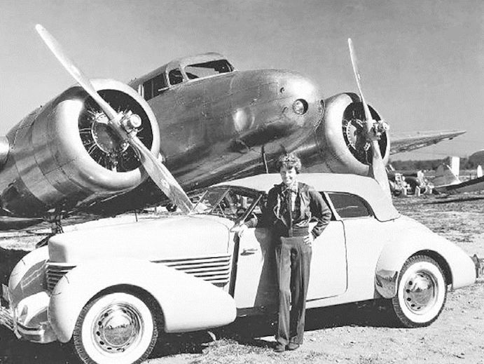
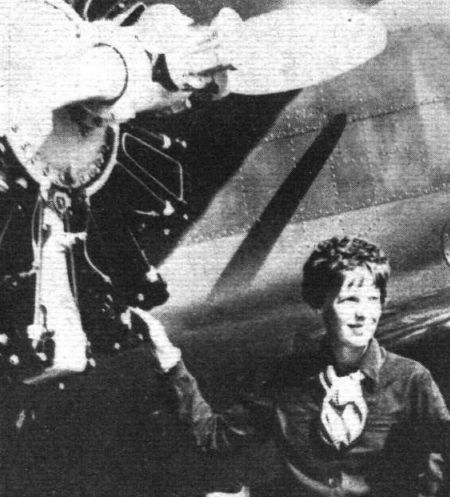
Авиация и Космонавтика 2017-03 / В.Морозов - Небо. Женщины. Самолеты
Амелия Эрхарт на фоне двухмоторного Локхид «Электра» L-10E, на котором она 20 мая 1937 г. начала свой трагически закончившийся перелет вокруг земного шара. Автомобиль марки «Корд» на переднем плане - очередная дань рекламе
-

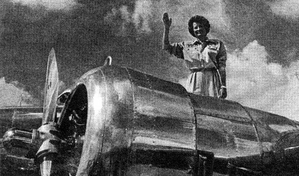
Aeroplane Monthly 1989-02 / R.Nesbit - What did happen to Amelia Earhart? (2)
Amelia in front of her Lockheed Electra.
-

Flight 1937-01 / Flight
Mrs. Amelia Earhart Putnam seen with the Lockheed Electra "Flying Laboratory" belonging to Purdue University.
-

Мировая Авиация 114
Эрхарт около самолета Electra 10E с Полом Манцем (слева), Гарри Маннингом и Фредом Нунаном (крайний справа) - ее экипажем в первой, неудачной, попытке кругосветного перелета 17 марта 1937 года.
-

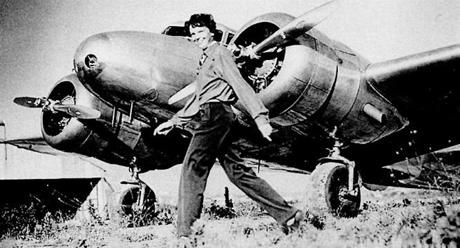
Мировая Авиация 114
Смелость и жизнерадостность были отличительными чертами характера Эрхарт. На снимке - Амелия на фоне своего последнего самолета Electra 10E.
-

Авиация и Время 2005-04 / А.Мандель - Первая леди Атлантики /Портреты/
Одним из самых известных Electra был этот 10-E летчицы Амелии Эрхарт. Он нес увеличенный запас топлива и был оснащен дополнительным навигационным оборудованием для полетов на большие расстояния.
Эрхарт возлагала большие надежды на свой новый самолет Локхид "Электра" -

Авиация и Космонавтика 1997-07 / В.Беляев - Парижский авиасалон
Линда Финч посвятила свой перелет памяти Амелии Эрхарт
-

Aeroplane Monthly 1989-02 / R.Nesbit - What did happen to Amelia Earhart? (2)
Регистрационный номер: NR16020 [2] Amelia's specially-modified Electra, NR16020, photographed upon its delivery from Lockheed.
-

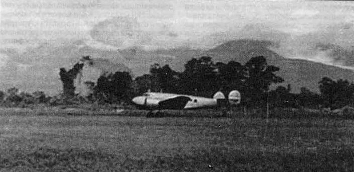
Авиация и Время 2005-04 / А.Мандель - Первая леди Атлантики /Портреты/
Последний взлет Амелии Эрхарт. Лаэ (Новая Гвинея), 2 июля 1937г.
-
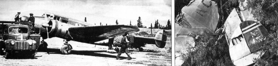
Авиация и Время 2010-02 / А. и Е.Соловьевы - Жизнь длиной в три авиакатастрофы
Регистрационный номер: NC14915 Загрузка "Электры" Гиллома, 1942г. Обломки этого самолета, февраль 1943г.
-

Aviation Historian 11 / N.Stroud - Kill 'em, Chill 'em & Fly 'em Out!
Регистрационный номер: VH-ABV [3], VH-MMD [3] Beef is unloaded at Perth from Lockheed 10A Electra VH-ABV in July 1946, contrary to some reports which claim that the aircraft was VH-ABW and the date the following year. Official reports erroneously state that the aircraft used on the first beef run to Perth was “VH-MMD (then called VH-ABW)”; ’MMD was in fact VH-ABV before being re-registered in October 1948, and ’ABV was based in Derby at the time, making it a more likely candidate.
-

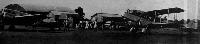
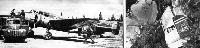
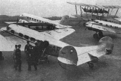
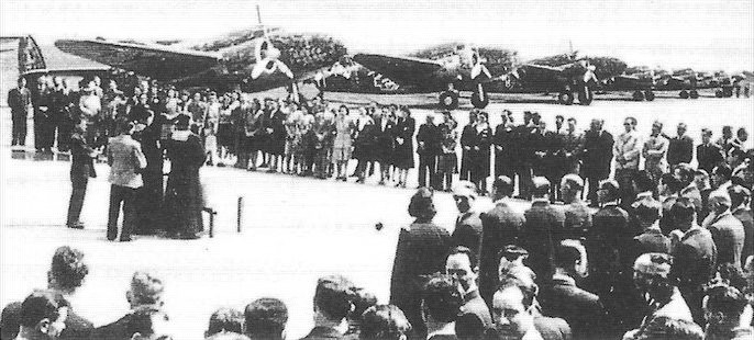
Air Enthusiast 1996-09 / M.Axworthy - Flank Guard. Romania's Aerial Advance on Stalingrad (2)
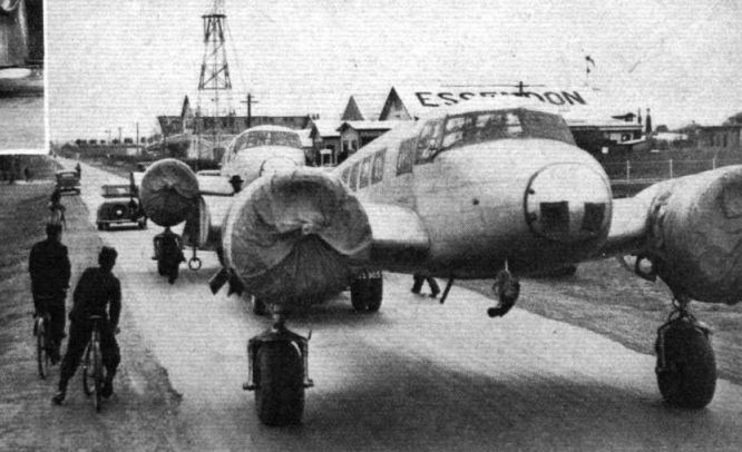
Three ex-LOT Lockheed 14 Super Electras nearer the camera, and three Lockheed 10A Electras in the distance. This photograph is thought to be of the commissioning ceremony of the ‘Escadrila’ LARES in June 1941.
Другие самолёты на фотографии: Lockheed Super Electra 14 - США - 1937
-
Air-Britain Archive 1994-03
Регистрационный номер: YR-LEF Electra YR-LEF wearing the dappled green/brown camouflage and white fuselage band as used by LARES during the war.
-
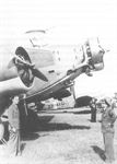
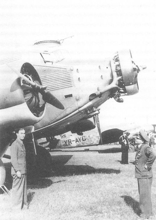
Air Enthusiast 1996-07 / M.Axworthy - Flank Guard. Romania's Aerial Advance on Stalingrad (1)
Регистрационный номер: YR-AFC In the background is Lockheed 10A Electra YR-AFC, which was the most common airliner in LARES service before the war, and the most common transport in the ‘Escadrila’ LARES in 1941. The mottled wartime camouflage scheme was that adopted by most civil airliners. It is thought to have been the underlying LARES light grey overpainted with the dark olive green used as the base colour on FARR aircraft. In the foreground is a Ju 52; the type that succeeded the Lockheed as the most common transport from 1942. LARES also had a single civil registered Ju 52 in 1941.
Другие самолёты на фотографии: Junkers Ju.52/3m - Германия - 1931
-
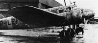
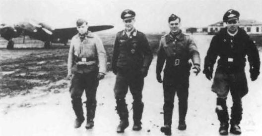
Air-Britain Archive 1994-02
Gerard Terry wants to know if anyone recognises the scene here. It shows a Lockheed Electra with Luftwaffe personnel strolling by. Could it be ex LOT, LARES or perhaps Aeroput? Any suggestions?
The Lockheed Electra photo is identified by Thomas Willis as having been taken in Rumania, probably about 1942/3. Three LARES Electras had streamlined DF aerials like the one in the photo, YR-LEE, -LEF and -LEG, so it may be one of these, however five ex-LOT Electras were operated by the Rumanian Air Force from 9.39. -

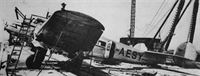
Flight 1937-10 / Flight
Road-clearers - Lockheed Electras on their way from the docks to Essendon Aerodrome, Melbourne.
-
Air Enthusiast 2001-07 / C.Justo - Ten Out of Ten
Регистрационный номер: VH-UZO [7], G-AFTL [7] VH-UZO wearing KNILM colours in 1998.
-

Flight 1939-06 / Flight
Engineers removing the starboard undercarriage of a Lockheed Electra prior to fitting a routine replacement unit.


-

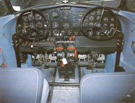
Flight 1937-04 / Flight
Inside the control cabin of one of British Airways Electras. The central throttle bank carries c.s. airscrew controls on the left and mixture controls on the right, while below are the undercarriage, flap, and carburettor-heater controls. Among the less usual instruments may be seen the mixture analyser (behind the throttles), the cylinder-head and outside air temperature gauges, and the blind approach indicator. The wireless panel and controls on the right have now been removed, since the operator has his own premises aft of the pilot's cabin. Behind the port wheel can be seen the Lorenz blind-approach dial, a radio homing indicator and the normal Sperry equipment. Behind the port throttle lever is the exhaust gas analysing indicator - especially necessary with constant-speed airscrews.
-
-

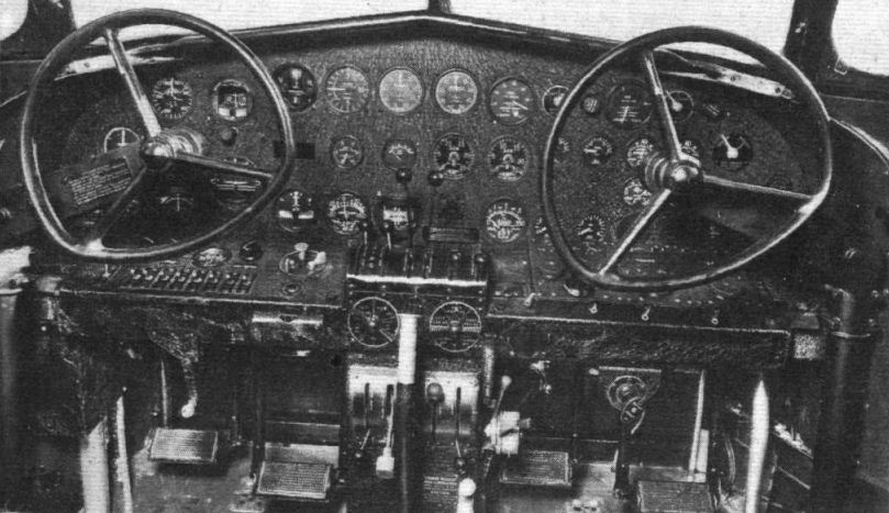
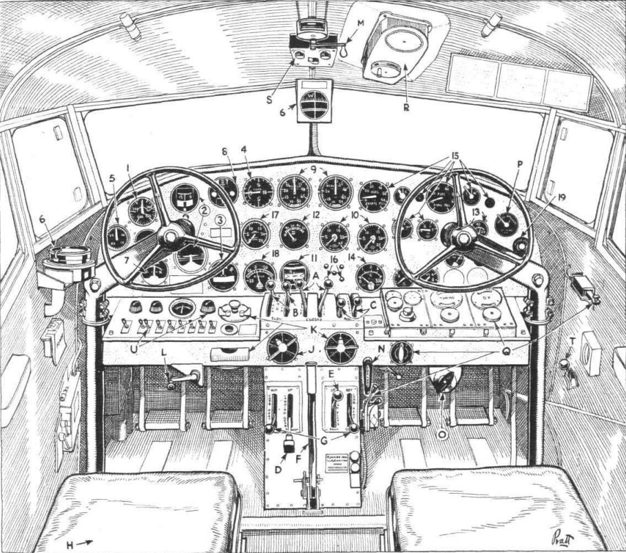
Flight 1937-04 / Flight
This drawing of the control cabin of the Lockheed Electra shows all (or nearly all!) the controls and instruments. In the interests of clarity the former have been distinguished from the latter by the use of letters instead of numbers.
(A) Throttles (B) Airscrew governor controls. (C) Mixture controls. (D) Undercarriage control. (E) Flap control. (F) Brake lever. (G) Carburettor heater controls. (H) (beside seat) Emergency undercarriage control, fuel dump valves and master switch. (J) Fuel valves. (K) Ignition controls. (L) Directional trimmer. (M) Fore and aft trimmer (N) Emergency fuel pump. (O) Engines primer. (P) Vacuum switch-over. (Q) Marconi remote panel and controls. (R) Marconi remote control for D/F loop. (S) Lorenz control panel. (T) Cabin temperature control. (U) General switchboard and de-icer regulator.
(1) Air-speed indicator (2) Sperry horizon and gyro. (3) Turn indicator. (4) Rate-of-climb indicator. (5) Kollsman sensitive altimeter. (6) Compasses. (7) Marconi homing indicator. (8) Lorenz indicator. (9) Manifold pressure gauges. (10) Revolution counters, (11) Cambridge exhaust analyser. (12) Flap indicator. (13) Carburettor temperature gauges. (14) Cylinder head temperature gauge. (15) Fuel gauge dials and switches. (16) Undercarriage warning lights. (17) Vacuum indicator. (18) Air temperature gauge. (19) Passengers' signal light. -

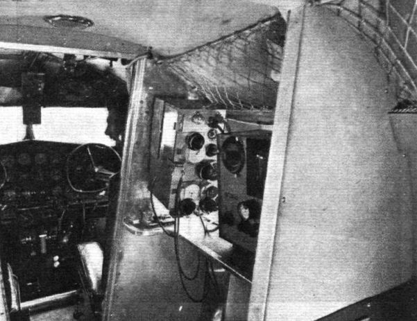
Flight 1937-06 / Flight
Marconi installation in a British Airways Lockheed Electra. On the forward bulkhead is the receiver-transmitter unit, and in the cockpit roof is the D/F loop indicator which has a repeater on the panel in the foreground.
-

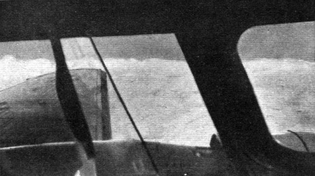
Flight 1937-12 / Flight
OVERWEATHER: An impression through the port windows of the control cabin of a British Airways Electra flying in the sunshine at 9,000 ft. over what is probably a damp and dismal English countryside.
-

-

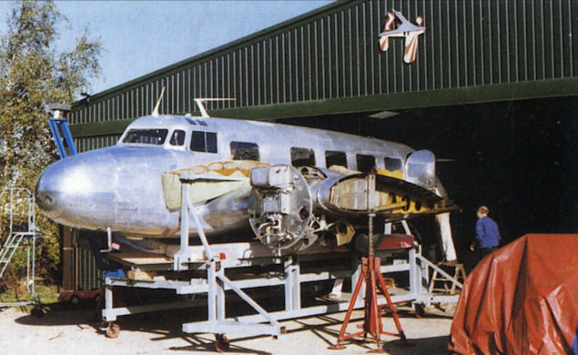
Aeroplane Monthly 2000-01 / M.Oakey, T.Harmsworth - News
The Electra being readied for its journey to London.
-

Air Pictorial 1991-10 / J.Grant - Salvage... bush fashion
Регистрационный номер: VH-ABV [3], VH-MMD [3] RMA Gascoyne at rest in the pindan immediately after crash landing
-

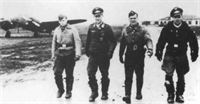
Air Pictorial 1991-10 / J.Grant - Salvage... bush fashion
The repair crew: left to right; Gordon Smith, Billy Goad, Jim Branch, Roy Guest, Frank Ronaldi, Frank Colquhoun and Ned Delower. The aircraft is standing on its wheels again having just been jacked up free of the mud.
-

Aeroplane Monthly 1989-01 / R.Nesbit - What did happen to Amelia Earhart? (1)
A portent of worse to come. The heavily damaged Electra at Luke Field, Ford Island on March 19, 1937. It was shipped back to Burbank for repairs, which cost $14,000, and was back in the air two months later. Earhart raised some of the money to pay for it through giving lectures.
-

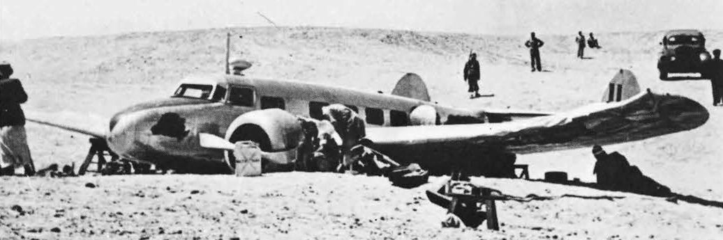
Air-Britain Archive 1987-01 / U.K. Validations (2)
Регистрационный номер: G-AEPR [2] Lockheed 10A Electra G-AEPR, B.O.A.C.'s "Leith", was an aircraft with a part in history. It was used to fly Neville Chamberlain to Germany to meet with Adolf Hitler in September 1938 and on 3.9.39 became the RAF's first Electra. It was used by NAC in civil marks until destroyed in this crash at Almaza on 14.4.44.
-

Air-Britain Archive 1992-03 / Casualty Compendium (46)
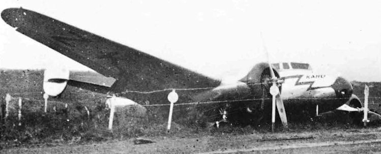
Регистрационный номер: ZK-AGJ "Well done, Kahu, managed to stop within the airfield boundary I see." Not a difficult one to identify but it was not a write-off so the date and place may cause the greater head-scratching.
"Kahu" was Lockheed 10A ZK-AGJ c/n 1127 of Union Airways which skidded on landing on wet ground at Bell Block aerodrome, New Plymouth on 23.7.39. Left u/c and wing tip were damaged, as were the propellers, and after temporary repairs the Electra was flown out to Milson on 15.8.39. -

Air-Britain Archive 1989-04 / Casualty Compendium (35)
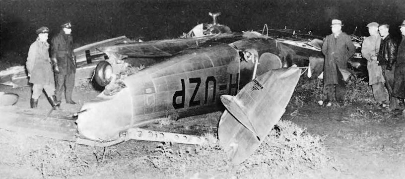
Регистрационный номер: VH-UZP [2] Lockheed 10B c/n 1109 of Ansett made a forced landing on 16.5.46 at Virginia 20 miles from Adelaide in heavy rain and poor visibility. Ten passengers and crew escaped with minor injuries.


-
Flight 1933-07 / Flight
THE LOCKHEED "ELECTRA": A photograph of a model. The arrangement of the cabin windows in the actual aircraft will differ from that shown here; the front windows will slope inwards in the latest American fashion.
-

-

Aeroplane Monthly 1989-01 / R.Nesbit - What did happen to Amelia Earhart? (1)
Lockheed Electra 10-E NR16020
-

Aeroplane Monthly 1989-01 / R.Nesbit - What did happen to Amelia Earhart? (1)
Diagram showing allocation and amounts of fuel and oil for Amelia Earhart’s Lockheed Model 10-E Electra at the time of its final flight.
-

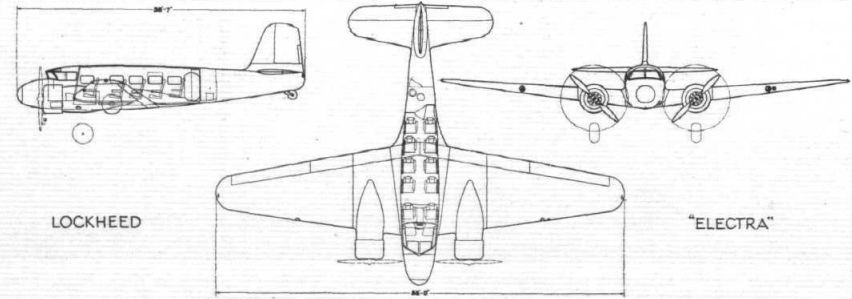
Flight 1934-01 / Flight
Lockheed "Electra"
-

Air Enthusiast 1972-05 / ??? - Sire of the U-2: the Lockheed 12-A
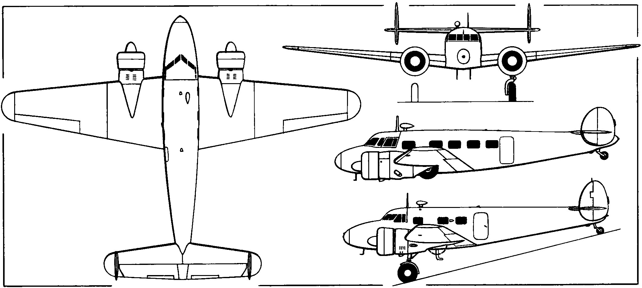
General arrangement drawings of the Lockheed 12-A with (upper side view) the Lockheed 10A Electra to the same scale.
Другие самолёты на фотографии: Lockheed Electra Junior 12 - США - 1936


Тип фотографий
- Все фото (114)
- Боковые проекции (1)
- Цветные фото (10)
- Ч/б фото (84)
- Кабина (6)
- Реставрация (1)
- Обломки (6)
- Рисунки, схемы, чертежи (6)