English Electric P.5 Cork и Kingston
В 1918 году фирма "Phoenix Dynamo Manufacturing" вошла в состав компании "English Electric", поэтому разработанную этой фирмой летающую лодку, ныне известную как English Electric P.5 Cork, правильнее было бы называть Phoenix P.5 Cork. Она упоминается здесь из-за ее прямого отношения к некоторым последующим проектам фирмы "English Electric". Серия летающих лодок Porte, разработанных в разгар Первой мировой войны, в общем оказалась удачной. В 1917 году Адмиралтейство решило заказать две такие лодки для оценки нового корпуса типа монокок, разработанного лейтенант-коммандером Линтоном Хоупом. Эти корпуса собрала компания "Southampton" ("May", "Harden & May Ltd.") в своих мастерских в Хэмптон-Уике на Темзе. Фирме "Phoenix" из Брэдфорда поручили построить остальную часть планера и выполнить окончательную сборку. Сначала в Бру собрали лодку P.5 Cork Mk I. Ее постройку завершили в начале августа 1918 года.
Приемные испытания начались на острове Грэйн чуть позже, но крылья пришлось вернуть на завод для замены бракованного лакового покрытия. Крылья на второй лодке P.5A Cork Mk II также заменили. Для улучшения характеристик второго самолета на воде нижнее крыло у него слегка приподняли над фюзеляжем, установив на пилонах, и увеличили руль направления. На верхнем крыле имелась пара гондол, в которых стояли турели с 7,7-мм пулеметами Lewis. В связи с заключением перемирия самолет в серию не пошел, но эксперименты с двумя прототипами продолжались еще несколько лет. В итоге вторую лодку Cork (Mk III) оснастили двумя моторами Napier Lion мощностью 450 л.с. (336 кВт). Она стала базой для следующей конструкции - лодки Kingston.
Эскизный проект нес то же обозначение Cork, но лодка P.5 Kingston обладала рядом улучшений. Первый Kingston взлетел в 1924 году с двумя моторами Napier Lion, опробованными на втором варианте Phoenix. Была заказана малая серия из пяти таких лодок. Они получили реконструированные поплавки на законцовках крыла, увеличенные элероны на верхнем крыле и увеличенное горизонтальное оперение.
Первый серийный Kingston разбился в ходе испытаний в Феликстоу в апреле 1925 года, но экипаж удалось спасти. Четвертый серийный экземпляр с новым дюралевым фюзеляжем обозначили Kingston Mk II. Последнюю серийную лодку назвали Kingston Mk III. Она опять получила деревянный корпус и обладала более высокими взлетными характеристиками. Kingston Mk III впервые взлетела в 1926 году. В марте того же года из-за отсутствия заказов фирма "English Electric" закрыла авиационный отдел. Лишь 23 года спустя появился следующий самолет компании - классический реактивный бомбардировщик Canberra.
ТАКТИКО-ТЕХНИЧЕСКИЕ ХАРАКТЕРИСТИКИ
English Electric P.5 Kingston Mk III
Тип: многоместная противолодочная летающая лодка - морской разведчик
Силовая установка: два W-образных поршневых двигателя Napier Lion no 450 л. с. (336 кВт) каждый
Летные характеристики: максимальная скорость 169 км/ч на уровне моря; набор высоты 1525 м за 12 мин 37 с; практический потолок 2800 м; дальность полета 837 км
Масса: пустого самолета 4336 кг; максимальная взлетная масса 6795 кг
Размеры: размах крыла 26,06 м; длина 17,41 м; высота 6,57 м; площадь крыльев 119,14м2
Вооружение: по одному подвижному 7,7 мм пулемету Lewis в носовой части и в гондолах на верхнем крыле, плюс до 472 кг полезной нагрузки под нижним крылом, включавшей две 236-кг бомбы либо четыре по 104 кг
Показать полностьюShow all
Flight, March 1924
THE "P.5" OR PHOENIX "CORK" FLYING BOAT,
And Some Other Products of the English Electric Co., Ltd,
A BRANCH of the English Electric Co., Ltd., whose ramifications extend very far afield indeed, and who have works at Bradford, Coventry, Preston, Rugby and Stafford, the aircraft works of the E.E.C., are established at Preston, Lancashire, while more recently a smaller works at Lytham has been taken over. At Preston and Lytham a great deal of interesting work is being and has been carried out, but this is work about which the general public hears relatively little, as the machines built there are to the order of the Air Ministry, and may not, therefore, be referred to in detail. Now, however, the restrictions surrounding one of the E.E.C. machines have been relaxed, and it has become possible to give an illustrated description of it in FLIGHT. This machine, known variously as the "P.5" (the works type number) and the Phoenix "Cork" (the Air Ministry name), although it cannot claim the interest attaching to the most recent types, having been built as long ago as 1918, is nevertheless very well worth a closer examination, as it incorporates certain features and improvements which not only placed it well ahead of certain much-used types at the time of its inception, but which make it even today a machine of very considerable merits. As an example, it may be mentioned that one of the "P.5" boats taking part in the development flight during 1922 acquitted itself so well of its task that it was regarded by many as being one of the best machines to take part, and this in spite of the fact that the actual machine was at the time already four years old.
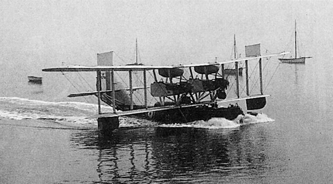
The Phoenix "Cork"
The responsibility for the design of the "P.5" rests with Mr. W. O. Manning, chief designer to the English Electric Company. Mr. Manning is, of course, well known in aviation circles, having been actively engaged in design and construction since the early days of flying. Thus it may be recollected that he was largely responsible for the somewhat curious "Coventry Ordnance" biplane which appeared at Brooklands in 1912. More recently Mr. Manning has been heard of in connection with the "Wren," perhaps the most extraordinary aeroplane ever built.
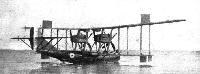
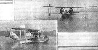
Fundamentally the "P.5" is a twin-engined flying boat, with a circular-section hull of the Linton-Hope type. The original "P.5," or Phoenix "Cork," was produced in 1918 at the request of the Air Ministry, as a machine was wanted to replace the then standard F.5 flying-boat. Owing to the Armistice, and to the fact that very large quantities of the F.5 type flying-boat had been produced and were in stock, the "P.5" was not produced in quantities, but the experiments with the first machine were so successful that slightly modified versions, known as the "P.5 Mark II" and "P.5 Mark III," were produced. These differed somewhat from the original machine, chiefly the Mark III, which has Napier "Lion" engines instead of the Rolls-Royce "Eagles" of the Marks I and II.
As reference has been made to the F.5 flying-boat, and the statement made that the "P.5" was designed to be an improvement upon that type, it may be of interest to take a few of the figures relating to the F.5, and to compare them with the corresponding figures for the "P.5," Marks I, II, and III. It has already been pointed out that the first two are fitted with Rolls-Royce "Eagle" engines, while the last has two Napier "Lions." Following is a table of comparative performances :-
"F.5" "P.5" Mk.I and Mk.II "P.5" Mk.III
Weight, light 9,100 lbs. 7,350 lbs. 8,000 lbs
Weight, loaded 12,700 ,, 11,600 ,, 12,500 ,,
Useful load 3,600 ,, 4,250 ,, 4,500 ,,
Horse-power 720 720 900
Speed at 2,000 ft. 76 knots 90 knots 95 knots
Climb to 2,000 ft. 7 mins. 4 mins. 3 m. 20 s.
Climb to 6,500 ft. 30 mins. 15 mins. 14 mins.
Climb to 10,000 ft. - 30 „ 25 „
Service ceiling 7,000 ft. 13,000 ft. 13,000 ft.
Construction
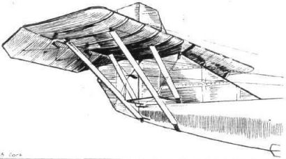
As already mentioned, the boat hull of the "P.5" is of the circular-section type introduced by the late Major Linton-Hope, but detail modifications have been introduced from time to time where experience has indicated the possibility of effecting improvements. The hull proper, as well as the planing bottom and fin top, is built up of two skins of mahogany, the inner skin being laid diagonally and the outer longitudinally. Varnished fabric is placed between the two skins, as the designer is of the opinion that this form of construction, although slightly more costly, results in greater durability. Three-ply wood has been entirely eliminated from the construction as a material which, however suitable for land machines, is unsatisfactory for seaplane work. The stringers and circular frames are of rock elm, as are also the cantilever members carrying the chine. The result is that the planing bottom can flex with the hull, which was not possible while the planing bottom was carried on rigid frames.
The space between the planing bottom and the main hull forms a watertight compartment, extending from the nose to the rear step, which occurs about half-way between the trailing edge of the lower plane and the stern post. This compartment is divided fore and aft by the keel member into two separate compartments, and each side is further subdivided into five separate watertight compartments by flexible watertight bulkheads. Thus the double planning bottom is divided into 10 separate watertight compartments, and even if all these were flooded the machine would be in no danger of sinking unless the inner hull had also been punctured. A bilge pump of ample capacity is provided, and drain plugs are fitted inside the hull so as to enable the double bottom to be pumped dry while the machine is afloat Drain plugs are also fitted on the outside of the planning bottom.
The wing-tip floats of the first "P.5" were of the usual rectangular section, with a V-bottom. In later types, however, floats of triangular section are employed, built up of a series of triangular frames supported by laminated circular hoops. This form of construction allows a slight amount of flexibility, much as does the main hull construction. The bottom and sides of the wing-tip floats are covered with double diagonal mahogany planking, through-fastened to the frames and timbers, which are closely spaced as in boat-building practice. The central frame is additionally stiffened, and serves as a watertight bulkhead, dividing each float into two watertight compartments without impairing the flexibility. Owing to their peculiar shape, these floats need not be carried on wire-braced struts, but can be attached direct to the under-side of the lower main plane.
Main Planes
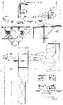
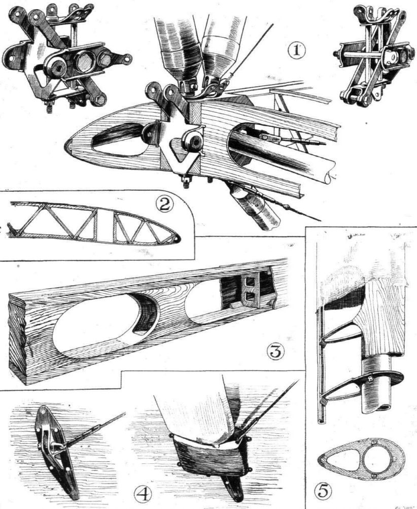
The main planes of the "P.5" (which are of T.16 section in Marks I and II) are built up of lattice ribs on box-section spars. The construction of the spars is indicated in one of our sketches. The top and bottom flanges are of spruce with distance blocks of various shapes separating them. Triangular-section fillets are employed in the corners of the box section to give greater glueing surface, and, finally, the sides of the spars are covered with spruce. The ribs are of lattice construction, three-ply having been eliminated entirely. The wing-spar fittings are of more or less orthodox design, built up from sheet steel. One such typical fitting, occurring at the junction of the wing root with the engine struts and sloping stay strut to the hull, forms the subject of three of our sketches, which should make the arrangement clear.
The interplane struts are of somewhat unusual construction, inasmuch as they consist primarily of circular-section steel tubes around which streamline fairings are built. This in itself is not new, but the construction of the fairings is unusual in that it consists of light ribs carrying a three-ply covering over the front third, with merely a doped fabric covering over the trailing portion. The steel tubes of the struts terminate in fork-ends, bolted to eyebolts passing vertically through the wing spars. The internal-drag bracing struts are also round steel tubes, but their end attachment is different from that of the interplane struts in that they simply abut on the spar and are located by shallow sockets welded to the fitting. In the sketch of the spar fitting these sockets can be seen surrounding a bolthead.
Large ailerons are fitted on the top plane only, and are operated by cables in the usual way.
The tail members are of orthodox design, the tail plane being braced from below by four struts. Although the angle of the tail plane can be altered by raising or lowering the attachment to the stern-post, no provision is made for trimming the tail during flight.
Power Plant
The two Rolls-Royce "Eagle" engines (Napier "Lions" in the Mark III) are mounted between V-interplane struts. and are entirely cowled-in, although the cowling is so arranged as to be readily detached for inspection or overhaul. Each engine drives a four-bladed tractor screw mounted high so as to be well clear of the spray.
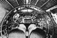
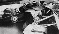
The petrol is carried in cylindrical tanks mounted in the hull, and each engine has a small gravity tank mounted under the top plane. The petrol is pumped up to the gravity tanks by two small windmills mounted on the deck of the hull. The large sprockets of the chain transmission may be seen in the photograph showing the interior of the hull. Smaller sprockets are, of course, mounted on the spindles of the windmills, so that the pumps are considerably geared down.
An engine-control lever of unusual design was fitted on the first "P.5." This was a single lever universally pivoted and operating by short rods and cranks two pulleys, one on each side. When the lever is moved forward without being tilted sideways both engine throttles are opened simultaneously. If, however, the lever is pushed over to the left, the starboard engine is given more throttle than the port one, and vice versa. The arrangement should be very handy, and should soon become quite instinctive in operation, but, for some reason or other, the pilots did not, we believe, like it, and engine controls of more orthodox design are now fitted.
The machine controls are of standard type, but very great attention has been paid to the reduction of the amount of physical effort required to fly the "P.5," and we believe that the machine is very much lighter on the controls than are the majority of machines of this size.
Hydraulic Tail-Trimming Gear
It has been mentioned that the "P.5" is not normally provided with a tail-trimming gear. If desired, however, a special gear, designed and patented by Mr. Manning, can be fitted. This is of the hydraulic type, and has been experimented with on other types of Mr. Manning's design. It is, we understand, giving good results, and should be particularly valuable on very large machines. Without going into technical details, which are reserved for a future article, it may be stated that with this gear the pilot trims the tail by operating a hand pump. By suitable setting of cocks the tail is then made to increase or decrease its angle of incidence. A very simple arrangement prevents the pilot from "overwinding" the gear, and continued pumping merely circulates the working fluid used through passages provided for the purpose.
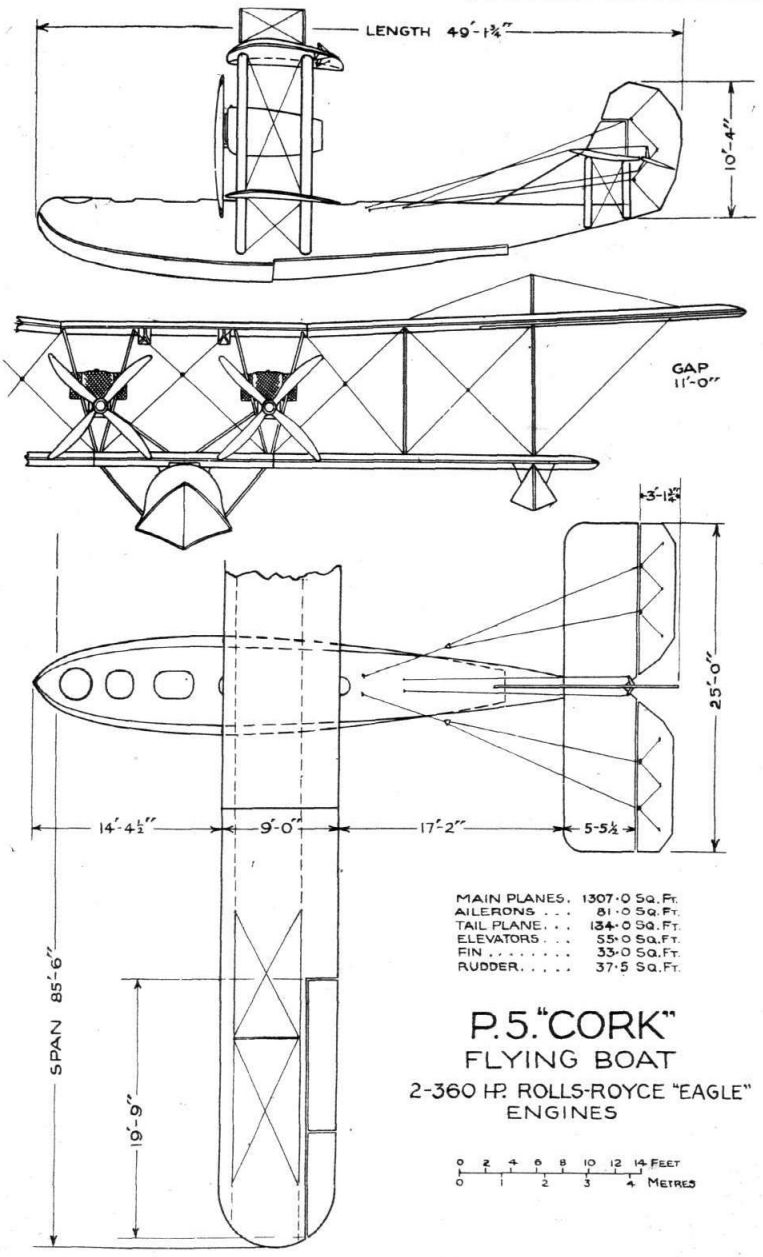
Following are the main characteristics of the "P.5" Mark II boat :- Length o.a., 49 ft.; span, 85 ft.; height, 21 ft.; hull length, 45 ft.; weight empty, 7,350 lbs.; useful load, 4,250 lbs.; total loaded weight, 11,600 lbs. Maximum speed, 90 knots (105 m.p.h.); cruising speed, 78 knots (90 m.p.h.); range at cruising speed, 800 miles. Climb: 2,000 ft. in 4 mins., 6.500 ft. in 15 mins., 10,000 ft. in 30 mins. Service ceiling, 13,000 ft. It will be seen that the empty weight is exceptionally low for a flying-boat, and that the ratio of empty weight to useful load is excellent.
The "P.5" Mark III, as already mentioned, is fitted with two Napier "Lions," and its main characteristics are:- Length o.a., 53 ft.; span, 85 ft.; height, 21 ft.; hull length 45 ft.; weight light, 8,000 lbs.; useful load, 4,500 lbs.; total loaded weight, 12,500 lbs. Maximum speed, 95 knots (110 m.p.h.); cruising speed, 78 knots (90 m.p.h.); range at cruising speed, 800 miles. Climb: 2,000 ft. in 3 mins 20 secs., 6,500 ft. in 14 mins., 10,000 ft. in 25 mins Service ceiling, 13,000 ft.
Other Types
Apart from the "P.5" and variations, the English Electric Company has designed and built several other types. As, however, these are to the order of the Air Ministry, and are not yet released for publication, it is not possible to make other than a brief reference to them.
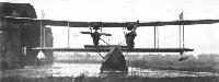
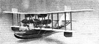
The "Kingston" has been developed from the "P.5" type, and is of slightly larger size, being fitted with two Napier "Lion" engines. A photograph of a scale model of the "Kingston" is published herewith, from which the general arrangement should be clear.
<...>
Показать полностьюShow all
Flight, November 1925
THE "KINGSTON" METAL-HULL FLYING BOAT
An Interesting Development by the English Electric Company
OWING to the fact that they have all been constructed for the Air Ministry, it has not been possible to refer in great detail to most of the machines produced by the English Electric company at their aircraft works at Preston, Lancashire, from time to time we have been able to publish photographs of such machines as have been released for publication by the Air Ministry, and this week we are able to give a general illustrated description of a fairly recent type, the "Kingston," the latest edition of which was successfully tested a few weeks ago.
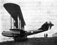
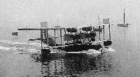
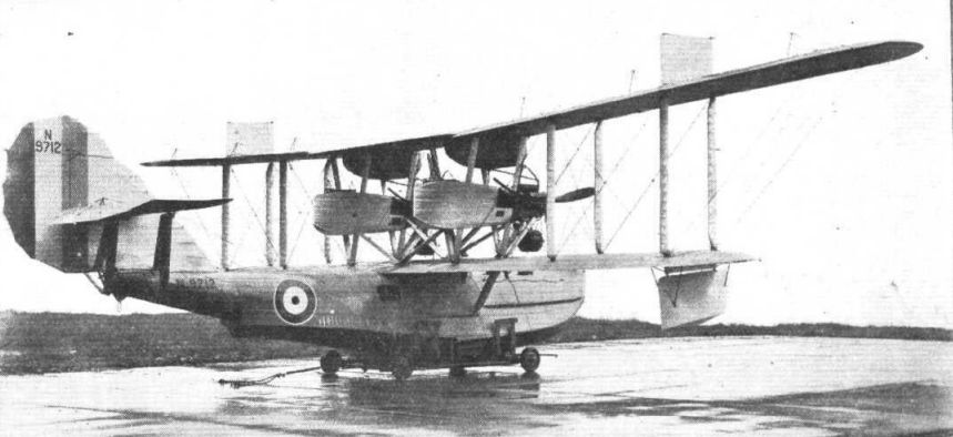
The English Electric Company's "Kingston" is a five-seater reconnaissance boat type fitted with two Napier ''Lion'' engines. In its original form the machine had the usual resilient mahogany-planked hull, but in the more recent development under review, the boat hull is an entirely new departure, not only because it is of metal construction, but equally on account of certain unusual features in its design. The special features of the "Kingston," and this applies to the earlier wooden-hull type as well as to the more recent metal-hull machine, are found in the arrangement of the engines and in the disposition of the wings, the upper of which has a pronounced dihedral, while the lower wing is perfectly straight.
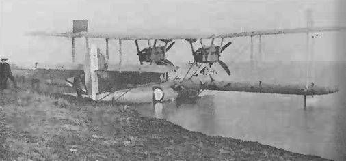
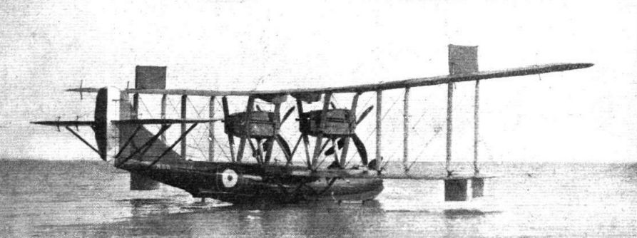
Although it is not permitted to give full detailed dimensions of the "Kingston," it may be stated, in order to give some idea of the size of the machine, that the top plane has a span of 85 ft. 6 in. The wings are of normal construction, that is to say, with wooden spars and ribs, and metal fittings. The wing section used is that known as T.64, which is a fairly thick section, giving room for spars of considerable depth. Both upper and lower planes are built in three sections. That is to say, that there are top and bottom centre sections permanently attached to the hull and to the engine interplane struts respectively, and the end portions of the wings are attached to these centre sections by horizontal pin joints in front and rear spars. As already mentioned, the end portions of the top plane are set at a pronounced dihedral angle, and further fin surface is provided by covering in the king posts supporting the top bracing of the top plane overhangs. The lower plane, the centre-section of which runs right across the top of the hull, is perfectly straight, i.e., without dihedral, with the result that the wing tip floats have a minimum of exposed supports. These wing tip floats are of unusual design, as will be seen in the photographs, and are remarkable for the fact that they are of approximately triangular section. The advantages claimed for this type of wing tip float, which has been developed by Mr. W. O. Manning, the firm's chief designer and engineer, and patented by the English Electric Company, is that it gives maximum displacement almost immediately on contact with the water. From the photographs of the machine resting on the water, for which we are indebted to the Lancashire Daily Post, it will be seen that the “Kingston” floats very high in the water and that the machine heels over but very little when at rest. We understand that the machine when at rest on a calm sea is practically neutral as regards stability, the wide beam of the hull over the chines serving to bring about this condition.
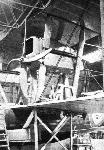
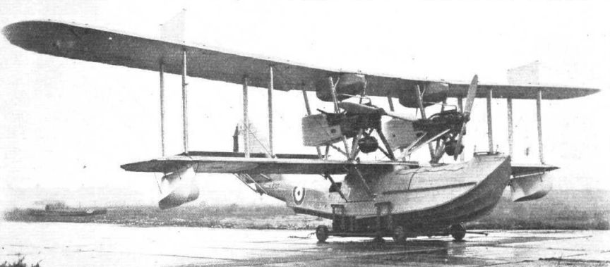
The arrangement of the interplane struts in the neighbourhood of the engines is somewhat unusual, and has been designed with a view to providing good accessibility for running repairs, as well as to render a change of engines easy. The oil tanks are mounted immediately behind the engines, while the petrol tanks are, it will be seen, suspended from the top centre-section so as to give direct gravity feed. The water circulation system is of somewhat unusual type, but may not at present be described in detail. The Air Ministry type of radiators are mounted below the engines, between the front engine struts, and it cannot be said that this type of radiator improves the appearance of the machine. Rearwards, the two engine nacelles are prolonged to form cockpits for two gunners, and it would appear that a particularly excellent field of fire should be obtained from these two positions. A cockpit for a third gunner is, it will be seen, provided for in the extreme nose of the hull, where in its raised position the cockpit should be well clear of flying spray.
The tail surfaces of the "Kingston" are of fairly orthodox design and construction, and it may be stated that the section employed in the tail plans and elevators is R.A.F. 14, inverted. A tail plane trimming gear is provided so as to enable the pilot to trim his machine at all flying speeds.
Hitherto our remarks have been equally applicable to the older and newer type of "Kingston."
When, however, we come to describe the hull, considerable departures are to be recorded. Not only is the hull of the latest "Kingston" of all-metal construction, the material used being mainly Duralumin, but the hull shape differs materially from that of the older machine.
Although following standard practice as regards its two steps, the lines of the "Kingston" metal hull are unusual. To begin with, it will be noticed that the stern portion of the hull does not show the usual up-tilted appearance. Instead of the cocked-up tail usually found, Mr. Manning has, in the metal hull of the "Kingston," continued the smooth lines of the hull, and has obtained the same effect, i.e., that of getting the tail well clear of the water, by making the aft step of rather greater depth than usual.
In the design of the front step and of the bows of the hull Mr. Manning has struck out along entirely original lines. To begin with, the main transverse frames of the hull, or rather of the planing bottom, do not show the smooth V usually found, but are divided on each side into three flutings or corrugations. The longitudinal stringers which provide the ridges of these corrugations run right up to the stem, where they, as well as the chines, are swept upwards at rather a pronounced sweep. The high flaring bows have the effect of giving a "dry" machine, while the corrugations break the bow wave into three separate smaller waves, which curl over independently. The result seems to be that the wave, instead of being flung far out to the side, is curled under in three smaller sections without flinging up much spray.
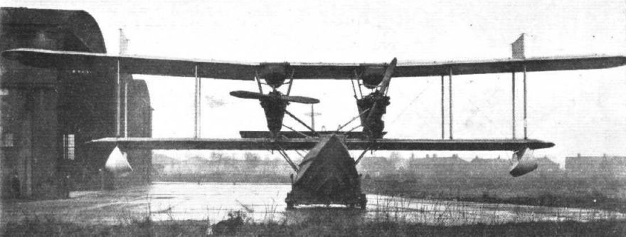
About the construction of the metal hull but little may be said, but we may state that it is of the single shell type, with athwarthship web frames and fore-and-aft stringers. Light auxiliary frames run from chine to chine, serving to stiffen the plating of the topsides. The fluted planing bottom, too, results, we understand, apart from the cleaner running which it gives, in greater structural strength, and is supported fore and aft by a number of intercostals. The hull planking is in the form of Duralumin sheets riveted to frames and stringers, from the front view of the machine it will be noted that the topsides of the hull have a pronounced tumble home, and that they are practically flat right down to the chines.
In this way the construction has probably been considerably simplified, apparently without any adverse effects as regards resistance. On each side of the forward portion of the hull there is a narrow footboard enabling the crew to pass front the various cockpits up to the engines, and to walk forward for the purposes of mooring the machine, handlines being provided to enable the crew to hold on in a rough sea.
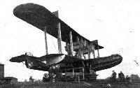
Attention should lie called to the special launching trolley by which the machine is handled. This trolley has large rubber-tyred wheels, steerable in pairs, and greatly facilitates the handling of the machine on the slipway.
Показать полностьюShow all


 Wiki
Wiki