

 Wiki
Wiki 
Варианты
- Gloster - I - III - 1923 - Великобритания
- Gloster - IV - 1926 - Великобритания
- Gloster - VI Golden Arrow - 1929 - Великобритания
Gloster IV
Фирма "Gloster" не стала строить самолет для состязаний на кубок Шнейдера 1926 года, но Генри Фолланд и его конструкторы уже работали над преемником Gloster III. Снова была выбрана схема биплана, так как Фолланд полагал, что она обеспечивает минимальную массу конструкции планера. На новый Gloster IV предполагалось установить еще более мощный вариант двигателя Lion, а аэродинамику довести до максимального совершенства. Поверхность крыла использовали для размещения радиаторов системы охлаждения двигателя, и впервые компания сама разработала поплавки, на верхней поверхности которых также были установлены радиаторы. Охлаждение мощных двигателей стало проблемой для разработчиков всех самолетов, принимавших участие в состязаниях. Чтобы сохранить температуру масла в допустимых пределах, Gloster IV оснастили маслобаком-радиатором под носовой частью фюзеляжа, а дополнительные поверхности охлаждения разместили по бортам, позади кабины пилота.
Построили три самолета: Gloster IV с безредукторным двигателем Napier Lion VIIA мощностью 900 л. с. (671 кВт), Gloster IVA с такой же силовой установкой, крылом уменьшенного размаха и оперением иной формы, а также Gloster IVB, аналогичный по конструкции Gloster IVA, но снабженный двигателем Lion VIIB, вращавшим винт через редуктор.
Именно Gloster IVB был выбран для участия в состязаниях, став третьим самолетом в британской команде, но машина была вынуждена выйти из гонки на шестом круге. Позднее Gloster IV был продан, но два оставшихся гидроплана продолжали использоваться ВВС для изучения высоких скоростей и для тренировок.
ТАКТИКО-ТЕХНИЧЕСКИЕ ХАРАКТЕРИСТИКИ
Gloster IVB
Тип: 1-местный гоночный гидросамолет
Силовая установка: один W-образный двигатель Napier Lion VIIB мощностью 885 л. с. (660 кВт)
Летные характеристики: максимальная скорость у земли 475 км/ч
Масса: пустого 1185 кг; максимальная взлетная 1499 кг
Размеры: размах крыла 6,90 м; длина 8,03 м; высота 2,79 м; площадь крыла 12,91 м1
Описание:
- Gloster IV
- Flight, August 1927
THE 1927 SCHNEIDER TROPHY CONTEST - Flight, March 1928
THE "GLOSTER IV”
Фотографии

-
Мировая Авиация 140
Регистрационный номер: N222 [8] Gloster IVА N222 (на снимке) был доставлен в Венецию 16 августа 1927 года вместе с Gloster IVB N223. Последний позднее принял участие в гонках на кубок Шнейдера того года, но победу в соревнованиях одержал Supermarine S.5.
-

Aeroplane Monthly 1993-10 / G.Nelson - Sam Kinkead
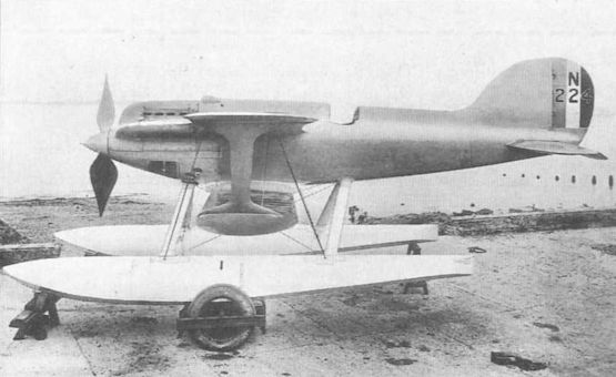
Регистрационный номер: N222 [8] Another view of Gloster IVA N222, this time with redesigned tail unit of cruciform shape, giving fin and rudder area above and below the tailplane.
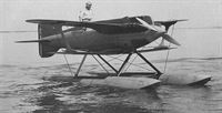
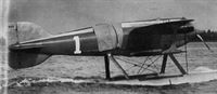
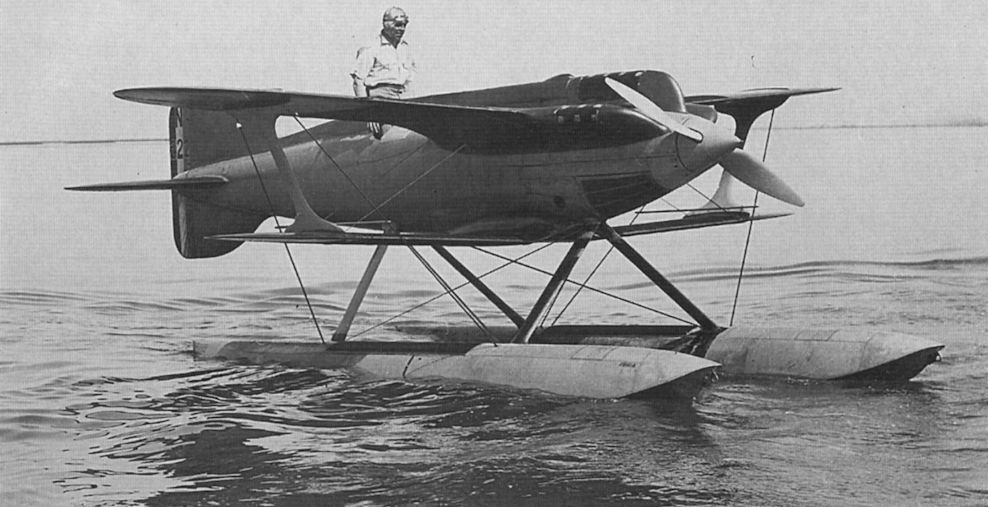
Gloster IVA N222 displays its sleek lines at Calshot shortly before the 1927 Schneider contest. The close cowling of the Napier Lion engine is evident. -

Flight 1927-08 / Flight
Регистрационный номер: N222 [8] THE BIPLANE CHALLENGER: Two views of the Gloster-Napier IV. Note the exceptionally neat fairing of the "Lion" engine which merges into the fuselage and wings.
-
Flight 1927-08 / Flight
Регистрационный номер: N222 [8] THE OTHER TWO BRITISH CHALLENGERS: So as to enable our readers to form a comparison of all three machines we give herewith views of the Supermarine-Napier S-5 and the Gloster-Napier IV - both of which were described in last week's FLIGHT.
Другие самолёты на фотографии: Supermarine S.5 / S.6 - Великобритания - 1927
-

Flight 1927-08 / Flight
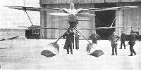
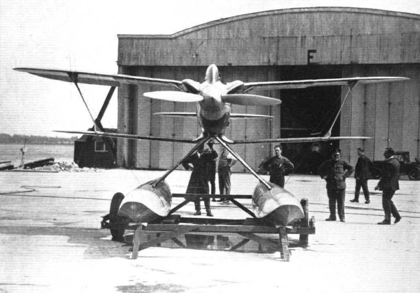
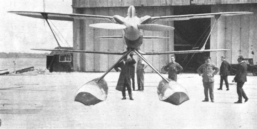
THE BRITISH CHALLENGER FOR THE SCHNEIDER TROPHY CONTEST: This front view of the Gloster-Napier IV biplane give an excellent idea of its clean lines.
-
Flight 1928-03 / Flight
THE "GLOSTER IV B": Front view. Note the excellent angles made by the bracing wires.
-

Flight 1927-09 / Flight
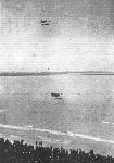
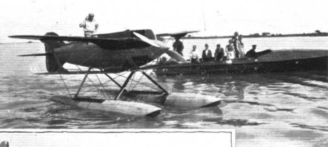
PREPARING FOR "THE DAY": One of two of the British Schneider Trophy Challengers make trial flights at Venice. Flight-Lieut. Kinkead, on the Gloster-Napier IV
-
Aeroplane Monthly 1993-10 / G.Nelson - Sam Kinkead
Регистрационный номер: N222 [8] Sam Kinkead stands in the cockpit of Gloster IVA N222 at Calshot in July/August 1927. Although this machine was shipped to Venice, it was not flown in the contest.
-

Aeroplane Monthly 1989-04 / A.Lumsden, T.Heffernan - Per Mare Probare (14)
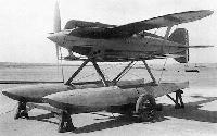
Регистрационный номер: N222 [8] Gloster IVA N222, with 900 h.p. Napier Lion VIIA engine.
-

Aeroplane Monthly 1989-08 / K.Wixey - Folland's racers (3)
Регистрационный номер: N222 [8] The Gloster IVA racing seaplane N222 with the 1929-type tail unit. This biplane was used by the RAF High Speed Flight at Calshot and Felixstowe for training in readiness for the 1929-31 Schneider Trophy contests.
-

Aeroplane Monthly 1989-08 / K.Wixey - Folland's racers (3)
Регистрационный номер: N222 [8] Gloster IVA N222 being pushed out into the water from the slipway prior to flight.
-
Aeroplane Monthly 1993-10 / G.Nelson - Sam Kinkead
Регистрационный номер: N223 [6] Gloster IVB N223 was the machine flown by Kinkead at Venice in September 1927, when a cracked propeller shaft forced its retirement.
-

Flight 1927-09 / Flight
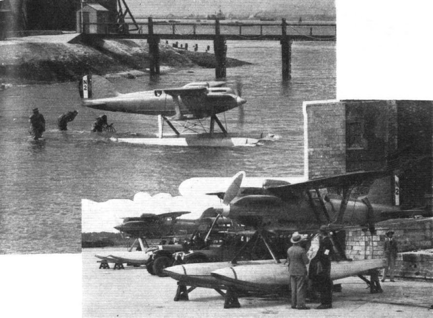
Регистрационный номер: N223 [6] THE SCHNEIDER TROPHY RACE: Three views of Lieut. Kinkead's Gloster-Napier, taking off, towing and taxying.
-

Flight 1927-09 / Flight
Регистрационный номер: N223 [6] THE 1927 SCHNEIDER CONTEST :- Flight-Lieut. Kinkead opens the Ball on the Gloster-Napier IVb.
-
Flight 1927-09 / Flight
GREAT BRITAIN GOING STRONG IN THE 1927 SCHNEIDER CONTEST :- Flight-Lieut Worsley on the Supermarine-Napier (direct drive) S.5 No. 6 being overtaken by Flight-Lieut. Kinkead on the Gloster-Napier No. IVb.
Другие самолёты на фотографии: Supermarine S.5 / S.6 - Великобритания - 1927
-
Flight 1927-10 / Flight
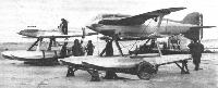
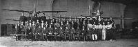
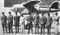
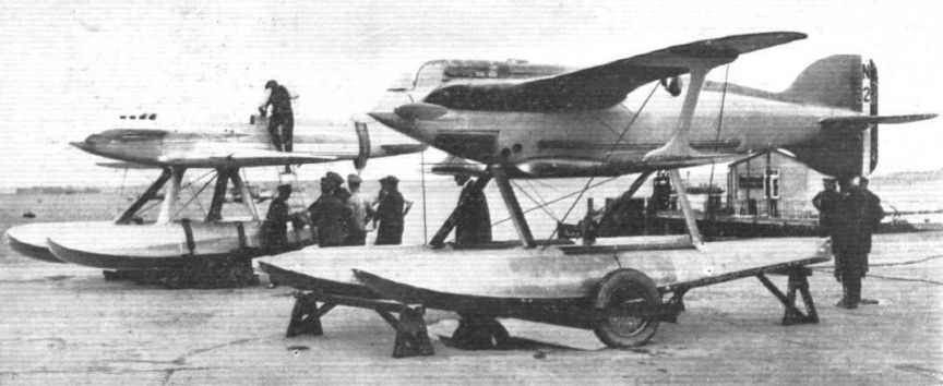
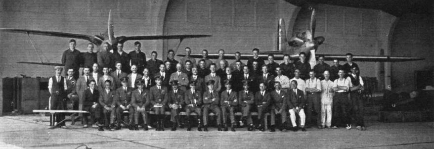
THE BRITISH SCHNEIDER TEAM: This photograph, taken at St. Andrea, shows the two types of British machines in the race, the Gloster IV on the left and the Supermarine S.5 on the right. In front of the machines are seen, among others: First Row - L. E. Coombes, Capt. Forsythe (Air Ministry), Flying-Officer Schofield, Flight-Lieut. Kinkead, Wing-Commander Fletcher, Flight-Lieut. Worsley (second in the race), Air Vice-Marshal Scarlett (Commander of the R.A.F. team), Flight-Lieut. Webster (winner of the race), Sqdn.-Ldr. Slatter, Flying-Officer Moon (Technical Officer of the team), Maj. Buchanan (Air Ministry) Mr. Ransome, and Mr. Reason. Second Row Mr. E. Scott, Sir Harry Brittain (Director of Napiers), Mr. Vane (Managing Director of Napiers), Mr. Folland (designer of the Gloster IV), Mr. Mitchell (designer of Supermarine S.5), Commander Bird (Managing Director of the Supermarine firm) and Mr. R. E. G. Smith.
Другие самолёты на фотографии: Supermarine S.5 / S.6 - Великобритания - 1927
-
Flight 1928-03 / Flight
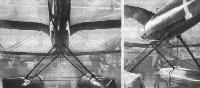
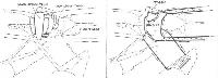
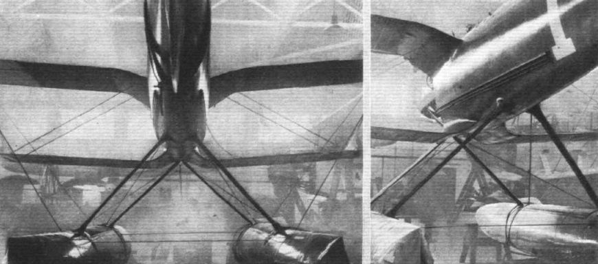
THE "GLOSTER IV B": Reducing interference was one of the great problems in the design. These photographs indicate how interference between wing roots and fuselage was reduced by avoiding sharp angles. The top plane fairs into the outer cylinder blocks, and the lower wing roots curve down and outwards, being initially at right angles to the surface of the body.
-

Flight 1928-03 / Flight
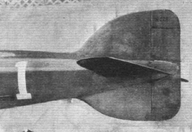
Регистрационный номер: N223 [6] THE "GLOSTER IV B": View of the nearly symmetrical tail surfaces.
-

Aeroplane Monthly 1989-04 / A.Lumsden, T.Heffernan - Per Mare Probare (14)
Регистрационный номер: N224 [4] The Gloster IV N224 with a special broad-chord Gloster metal propeller fitted to the 900 h.p. Napier Lion VIIA liquid-cooled, direct-drive, supercharged engine. The seaplane is also fitted with the tail unit ultimately adopted for the Gloster IVA and IVB in 1929.
-

Aeroplane Monthly 1991-06 / J.Havers - Field of endeavour (2)
Регистрационный номер: N224 [4] Te Gloster IV N224 seen here at Venice in September 1927.
-

Aeroplane Monthly 1989-08 / K.Wixey - Folland's racers (3)
Регистрационный номер: N224 [4] -
Flight 1929-09 / Flight
THE PRINCE WITH THE SCHNEIDER TEAMS: With the British team,
-

Aeroplane Monthly 1989-08 / K.Wixey - Folland's racers (3)
Регистрационный номер: N224 [4] Gloster IV N224. The floats were of Gloster's own design and were built from duralumin.
-

Aeroplane Monthly 1989-08 / K.Wixey - Folland's racers (3)
Регистрационный номер: N223 [6] The Gloster IVB N223 photographed at Calshot in August 15, 1929 when it was being used as a practice machine by that year's Schneider team. N223 was crashed by Flt Lt J. Boothman on December 19, 1930 while landing in fog.
-

Flight 1929-08 / Flight
Регистрационный номер: N223 [6] TWO OF THE TRAINING MACHINES: Two Gloster IV's with Napier "Lion" engines are being used for practice purposes by this year's Schneider team.
-

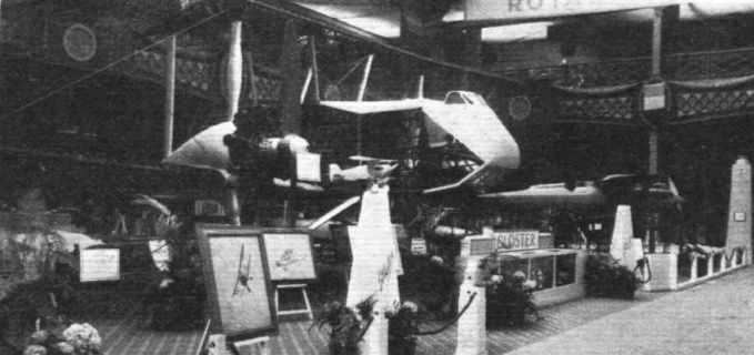
Flight 1929-07 / Flight
The Gloster Air Survey machine is exhibited in skeleton so that visitors may examine all the details. On the right is seen the "Gloster IV" racing seaplane.
Другие самолёты на фотографии: Gloster AS.31 Survey - Великобритания - 1929
-

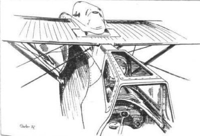
Flight 1929-07 / Flight
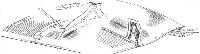
This sketch illustrates the special type of windscreen which is used to protect the pilot from the force of the terrific air stream in the Gloster IV.
-
Flight 1928-03 / Flight
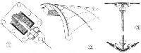
THE "GLOSTER IV B": 1, shows how anti-lift wires are prevented by rubber buffers from going slack when relieved of load. 2, the "double-diagonal" method of planking the fuselage. 3, showing how rivets are finished off flush with skin of float to reduce air friction.
-
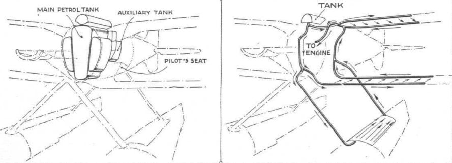
Flight 1928-03 / Flight
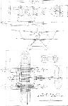
THE "GLOSTER IV B": On the left, the arrangement of the seven petrol tanks in the fuselage. There are three main tanks, three auxiliary tanks, and one service tank. On the right, a diagrammatic perspective representation of the water system, one-half only being shown. Note the radiator on the port float.
-
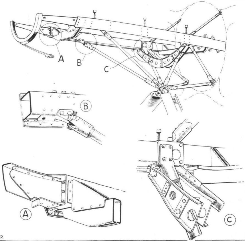
Flight 1928-03 / Flight
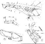
THE "GLOSTER IV B": Some constructional details. Above, a general view of the engine mounting; and below, some of its details.
-
Flight 1928-03 / Flight
THE "GLOSTER IV B": The wing surface radiators. On the left, the outer end of the lower plane radiator, showing also the Duralumin interplane strut. On the right, the water piping entering the fuselage at trailing edge of lower plane.
-
Flight 1928-03 / Flight
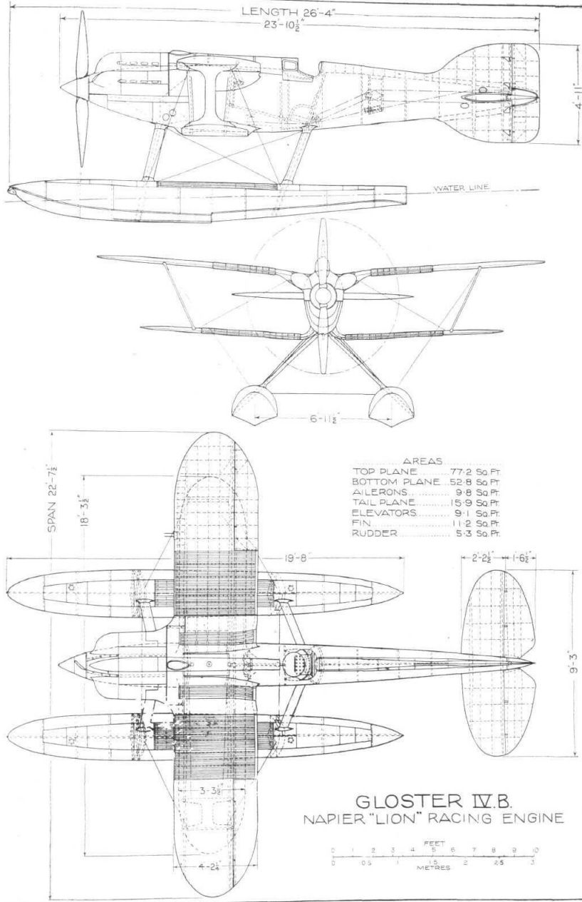
Gloster IV B Napier "Lion" Racing Engine


- Фотографии