
 Wiki
Wiki 
Flight, April 1921
THE CAPRONI "NINEPLANDEM" FLYING BOAT:
Eight 400 H.P. Liberty Engines
IN spite of its sudden demise during one of its first test flights, it appears worth while to place on record a few particulars of the large Caproni triple triplane; variously called the "Capronissimo," from the fact that Signor Caproni is said to contemplate much larger machines on similar lines, and the "Nineplandem," from the arrangement of its carrying surfaces. The machine was of such an extraordinary design that one felt doubtful as to it being controllable, when and if it once got into the air. We have no information as to the exact cause of the accident, but from what can be gathered it appears that lack of control may have been responsible for the dive into the sea. - ED.
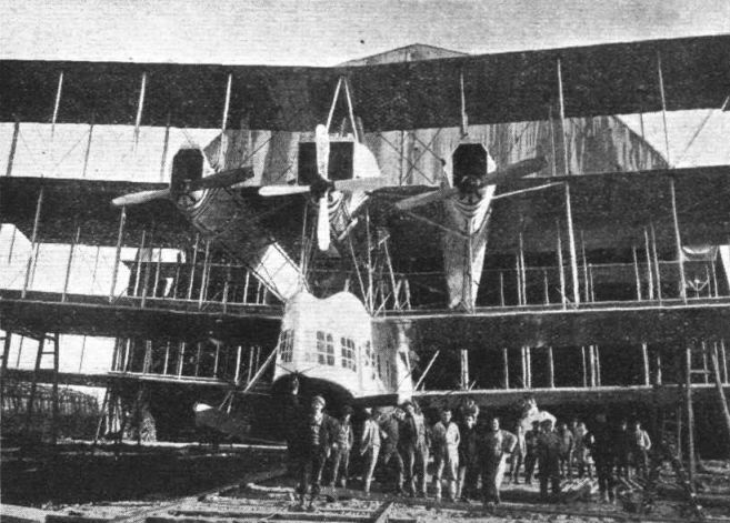
The reasons which led Signor Caproni to choose this unusual arrangement are various. In the first place, he is a great believer in multiple engines, and this arrangement has afforded him an opportunity of working in no less than eight, four at each end. The arrangement of these engines should be understood from one of the accompanying photographs, which shows the centre portion of the front triplane surface, and the nose of the main hull, as well as of the two auxiliary fuselages. Each of the latter carries in its nose an engine with nose radiator. Between the two fuselages is mounted a shorter engine nacelle, which carries two engines, one driving a tractor and one a pusher. The arrangement of the rear set of engines is similar, except that the three screws are pushers and one (the central one in the nose of the rear central nacelle) a tractor.
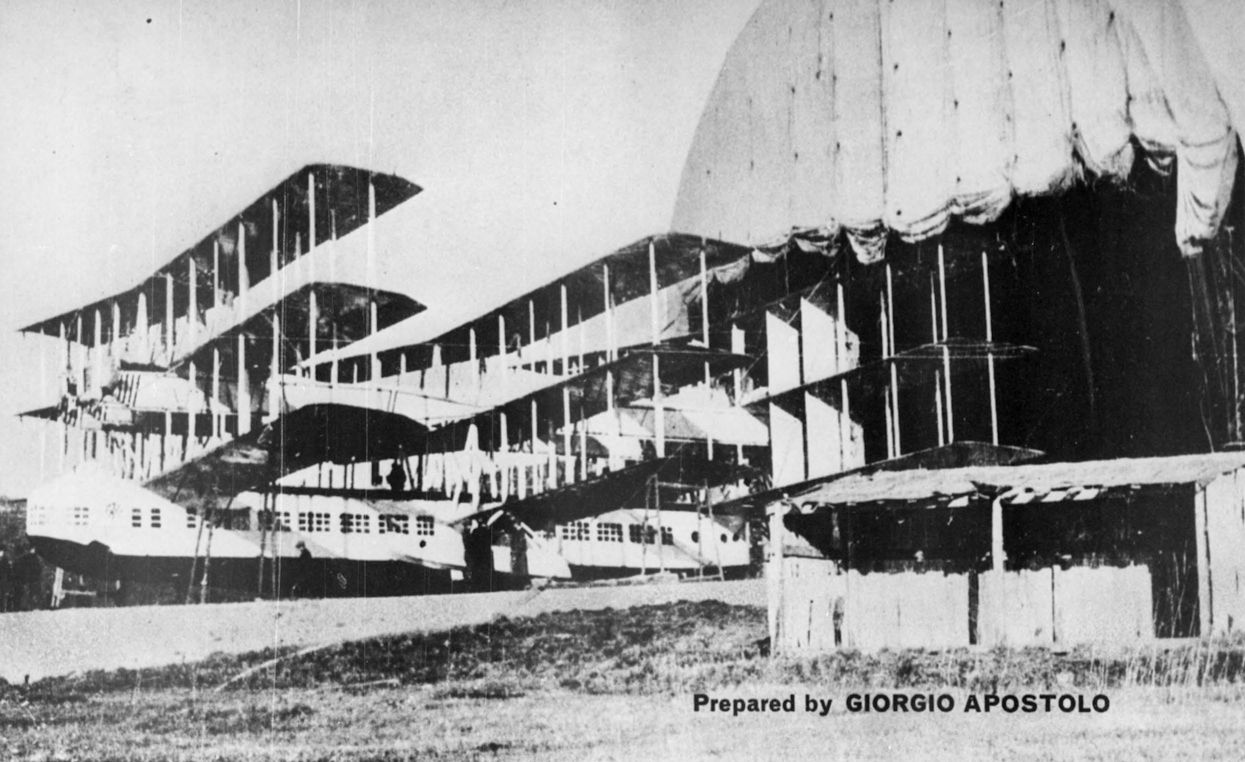
In addition to the two sets of triplanes at the ends of the machine, there is a third set midway between them. This set is so placed as to be on a slightly lower level than the other two. Whether this is done to get a certain amount of "stagger effect" is not known, but this seems probable. Lateral stability on the water is obtained by small auxiliary floats placed underneath the lower plane of this central triplane set. The main float hull is placed underneath the triplane surfaces, the lower planes of which rest on its roof, as regards the front and rear sets, while the middle triplane has its lower wing roots attached to the sides of the cabin,
The latter is a huge boat with fiat sides and Vee bottom with two steps, the front one of which occurs below the middle triplane, approximately under the centre of gravity, while the second and smaller step is under the leading edge of the rear set of triplanes. The passengers are seated along the sides of this enormous hull, and windows are provided along the entire length so as to give all the passengers a good view.
The engineers can crawl along the twin fuselage from stern to stern in order to get to the engines and effect minor repairs. In proportion to the span of the machine, the distance between the centre line and the outer engines is very small, and consequently it is hoped that the yawing couple in case of one of the side engines cutting out will be so small as to come easily within the scope of the rudders. These, by the way, are large biplane surfaces placed in the cellule of the rear triplane, and probably it is expected that they will make up in area for their absence of "leverage," placed as they are practically at the stern of the machine, certainly not behind it.
As regards lateral control, there does not appear to be any reason why this should be greatly different from that of the ordinary type of machine. Ailerons are fitted to all three sets of planes, and are so arranged that they act also as elevators. Exactly how this is accomplished we do not know, but probably the ailerons on the front set of triplanes move down when those of the rear set move up, while the centre set of ailerons retain their differential action as ailerons pure and simple. Whether this system proved effective enough is difficult to say. The trim of the machine, with the weight spread out longitudinally as it is, must be supposed to involve considerable forces, and whether the extra lift on one set, coupled with decreased lift on the set at the other end of the machine is sufficient seems somewhat doubtful. Much of the weight (that of four engines at each end), for instance, is concentrated at the ends, so that the longitudinal moment of inertia must be enormous. With regard to interference between the planes, we are informed that this has proved to be much smaller than one would expect from model tests. In other words, the efficiency of the planes is better than the arrangement would lead one to think. Be that as it may, it is probably longitudinal and directional control that will prove to be the bugbear of the tandem triplane arrangement.
Closely connected with this question of longitudinal control is the problem of taking off. Before this can be done, unless the machine is simply pulled along the water until there is enough force on the wings to lift it, without altering its attitude, the nose will have to be brought out clear of the water, while the rear of the hull is depressed, and one cannot help wondering whether this is a practical proposition. It is true that the machine did actually get off, but then she carried, in addition to pilot and mechanics, 1 1/2 tons of ballast only, which is a relatively small proportion of the weight of the 100 passengers. With full load the matter might be considerably more difficult.
Signor Caproni certainly deserves praise for his bold departure on such a large scale, and it is to be regretted that the accident has effectively stopped further experiments, but one hopes that some useful data may have been collected, which will show definitely whether or not the design is worth repeating. Following are the main data relating to the machine :
Span, 98 ft. 6 ins.; length o.a., 79 ft.; chord, 9 ft. 4 ins.; total wing area, 7,680 sq. ft.; weight of wings, 12,300 lbs.; weight of boat, 6,400 lbs.; weight of fuselages and nacelles, 3,520 lbs.; weight of engines, 10,600 lbs.; total weight empty, 32,800 lbs.; weight all on, 55,000 lbs.; cruising speed, 87 m.p.h.; fuel consumption, 1,100 lbs./h.; duration, 5 to 6 hours.
- Flight, April 1921
THE CAPRONI "NINEPLANDEM" FLYING BOAT:
Фотографии
-

-

Flight 1921-04 / Flight
The Eight-engined Caproni: Front view of central portion, showing nose of cabin and the housing of the four front engines. The rear engine set is similarly arranged, except that the three engines drive pusher screws.
-

Aeroplane Monthly 1974-02 / G.Apostolo - Caproni's Triple Triplane
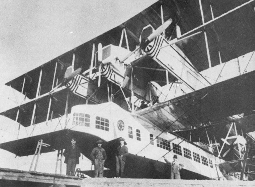
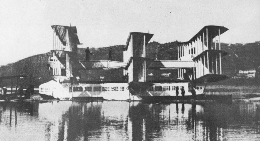
A good indication of the size of the seaplane. Note four-bladed propellers on middle push-pull engine.
-

Aeroplane Monthly 1974-02 / G.Apostolo - Caproni's Triple Triplane
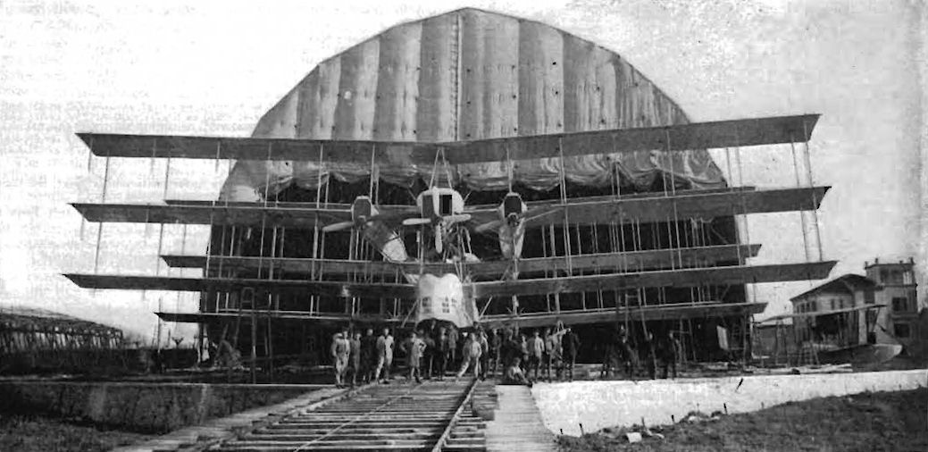
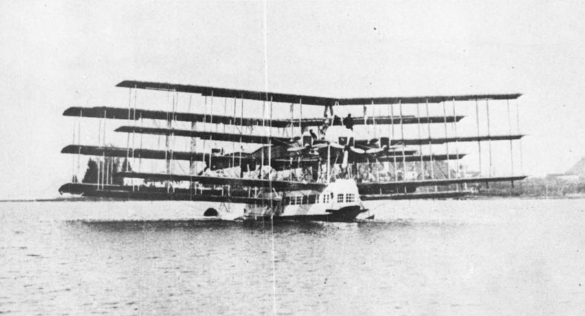
The “Noviplano” leaving the specially built hangar at Lake Calende.
-

Aeroplane Monthly 1974-02 / G.Apostolo - Caproni's Triple Triplane
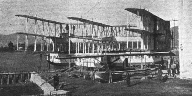
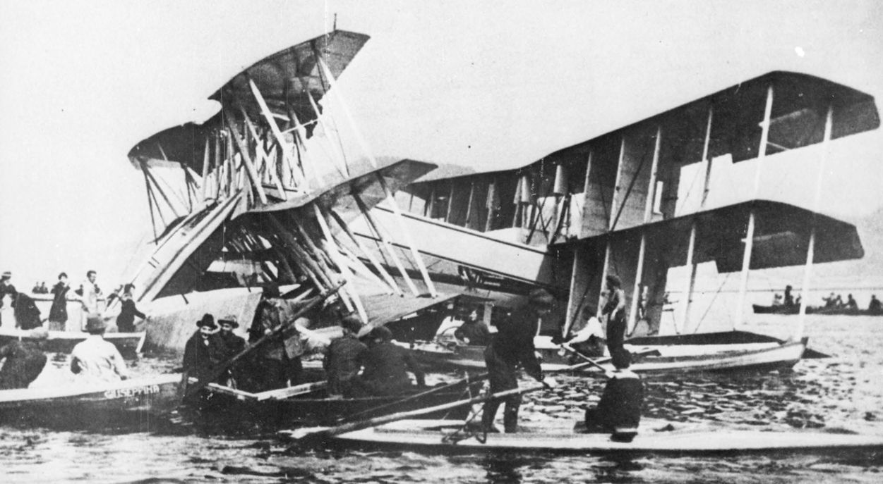
A mass of struttery, showing the fins and rudders to advantage. A smaller water-borne relative is beached in the foreground.
-

Flight 1921-04 / Flight
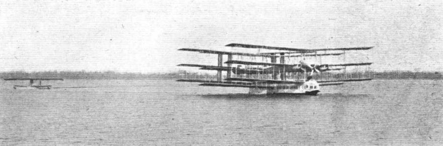
The Caproni "Nineplandem": Three-quarter rear view. A good idea of the size of the machine may be formed by comparison with the men, and with the single-engined flying boat standing in front of the large machine. Note the biplane rudders between the rear planes.
-

Aeroplane Monthly 1974-02 / G.Apostolo - Caproni's Triple Triplane
Just before flotation trials. Note men walking along the extended engine nacelles.
-

Aeroplane Monthly 1974-02 / G.Apostolo - Caproni's Triple Triplane
During flotation tests on Lake Maggiore, near Lake Calende.
-

Flight 1921-04 / Flight
THE EIGHT-ENGINED CAPRONI TAXYING: Note the small flying boat on the left.
-

Aeroplane Monthly 1974-02 / G.Apostolo - Caproni's Triple Triplane
The Ca.60 after its disastrous nose dive into Lake Maggiore.
-

Flight 1921-04 / Flight
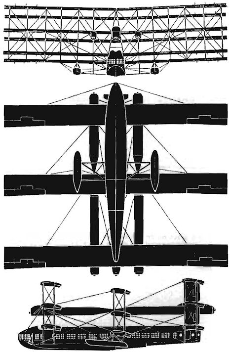
THE CAPRONI TRIPLE-TRIPLANE, EIGHT LIBERTY ENGINES: Scale diagrams and enlarged views of boat for various purposes. In the front elevation the lower plane only of the middle triplane is shown, in order to avoid confusion. The middle triplane, it will be seen, is on a slightly lower level than the other two.
-


- Фотографии