
Описание
 Wiki
Wiki 
Страна : Великобритания
Год : 1927
Единственный экземпляр
Двухместная авиетка
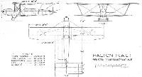
Halton H.A.C.1 Mayfly/ H.A.C.2 Minus
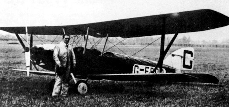
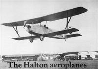
В 1926-1927 годах аэроклуб "Halton" построил двухместную легкую авиетку, названную Halton H.A.C.1 Mayfly. Этот простой биплан из дерева и ткани с мотором Bristol Cherub спроектировал С.Х. Латимер-Нидэм. Биплан впервые взлетел 31 января 1927 года. Вскоре его переделали в одноместный, сохранив то же обозначение. Однако с изменением конфигурации (из биплана в моноплан-парасоль) в начале 1928 года его переименовали в H.A.C.2 Minus. В этой конфигурации аэроплан добился некоторых успехов в соревнованиях, а также принял участие в авиагонках на королевский Кубок 1928 и 1929 годов. Его разобрали в 1930 году.
ТАКТИКО-ТЕХНИЧЕСКИЕ ХАРАКТЕРИСТИКИ
Halton H.A.C.1 Mayfly
Тип: двухместная авиетка
Силовая установка: ПД Bristol Cherub с горизонтально расположенными двумя цилиндрами мощностью 32 л. с. (24 кВт)
Летные характеристики: максимальная скорость 134 км/ч; крейсерская скорость 121 км/ч
Масса: пустого аппарата 218 кг; максимальная взлетная 417 кг Размеры: размах крыла 8,69 м; длина 6,71 м
Описание:
- Halton H.A.C.1 Mayfly/ H.A.C.2 Minus
- Flight, September 1926
British Light ‘Plane Development & Lympne Meeting - Flight, February 1927
AIRCRAFT CONSTRUCTION UNDER DIFFICULTIES
Фотографии

-

Мировая Авиация 148
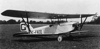
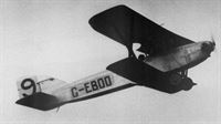
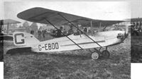
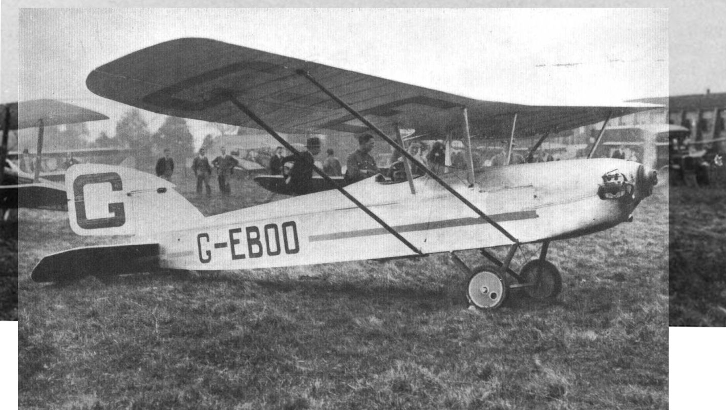
Регистрационный номер: G-EBOO [23] В исходной бипланной конфигурации это был аэроплан Halton H.A.C.1 Mayfly. Снимок сделан после первого полета.
-
Flight 1927-02 / Flight
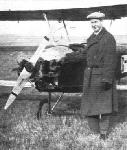
Регистрационный номер: G-EBOO [23] Mr. A. C. Kermode, B.A., Hon. Secretary of the Halton Aero Club standing by the "Mayfly."
-
Aeroplane Monthly 1974-08 / C.Latimer-Needham - The Halton aeroplanes
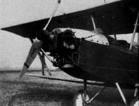
Регистрационный номер: G-EBOO [23] A close-up of the Mayfly’s 32 h.p. Bristol Cherub engine and Fairey-Reed metal propeller.
-
Flight 1927-02 / Flight
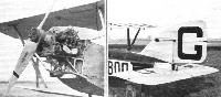
Регистрационный номер: G-EBOO [23] THE HALTON H.A.C.1: On the left the "Cherub" engine with its mounting, and the right the tail. Note the undivided elevator.
-

Aeroplane Monthly 1974-08 / C.Latimer-Needham - The Halton aeroplanes
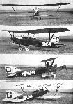
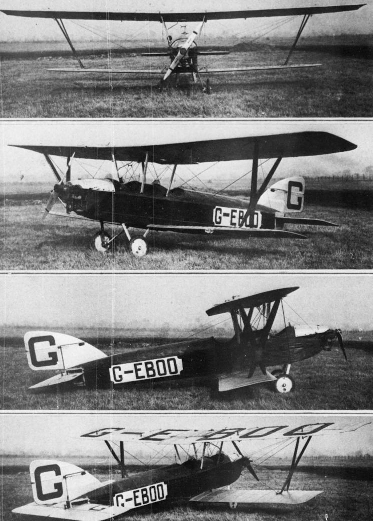
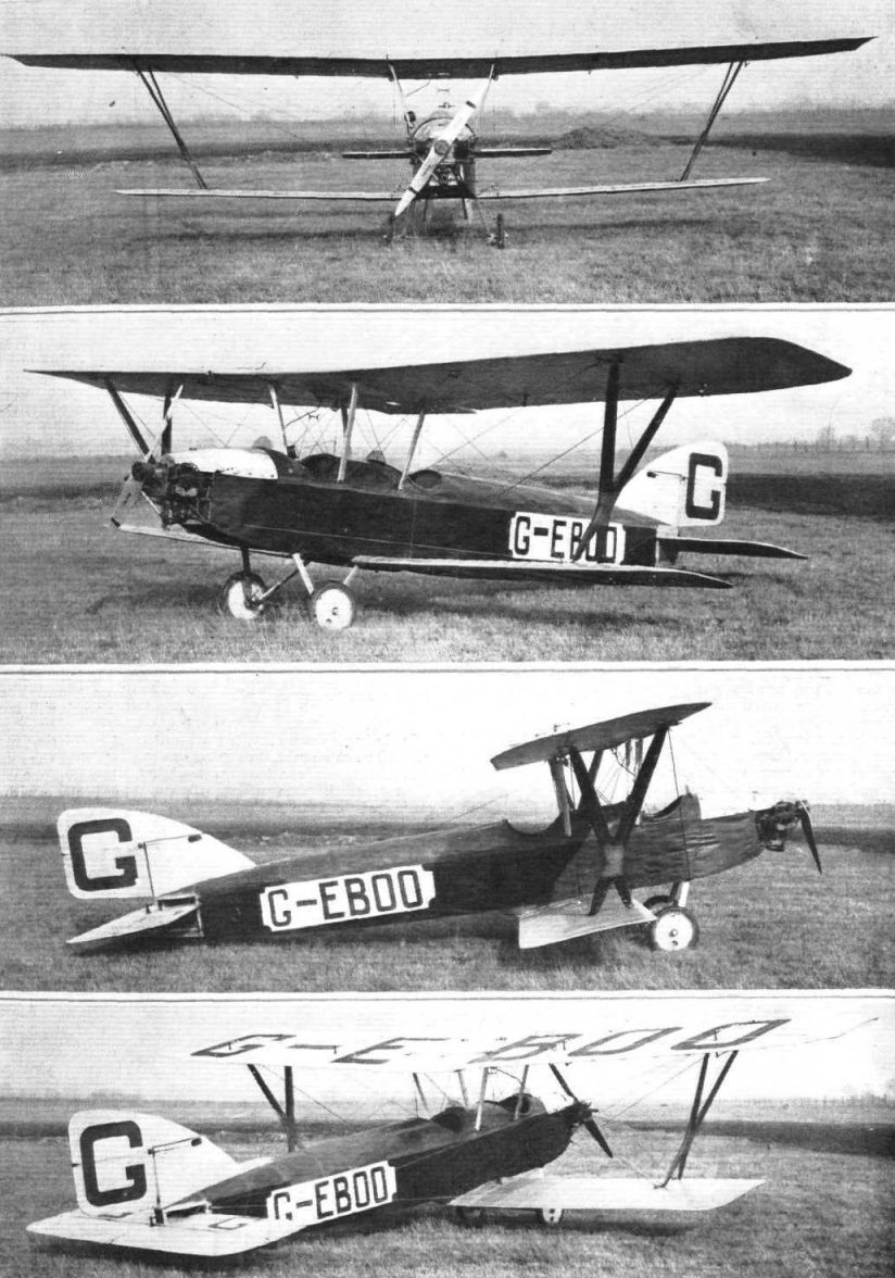
Регистрационный номер: G-EBOO [23] Four views of the Mayfly early in its life. Note the forward, unfaired, passenger seat and the unconventional interplane struts.
-
-
Aeroplane Monthly 2001-09 / P.Jarrett - Inter-war One-offs /Inter-war civil/
Регистрационный номер: G-EBOO [23] Not to be outdone, the Halton Aero Club, comprising 1,000 members from the RAF School of Technical Training at RAF Halton, built the HAC.1 Mayfly. Designed by C.H. Latimer-Needham, an educational officer at the station, it was entered for the 1926 Lympne trials but was not completed in time. Again Cherub-powered, it first flew on January 31, 1927, and was registered G-EBOO. At the end of the season it was converted into the HAC.2 Minus parasol monoplane.
-
Air-Britain Archive 1989-02 / U.K. Civil Register 1929 (2)
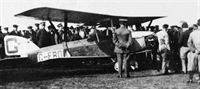
Регистрационный номер: G-EBOO [23] The Halton HAC1 Mayfly G-EBOO (32 hp Bristol Cherub III) is the centre of attraction for the Halton RAF apprentices who built it, first flight 31.1.27. With its lower wing removed it became the Minus parasol-wing monoplane, first flight 4.5.28.
-

Flight 1927-06 / Flight
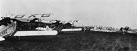
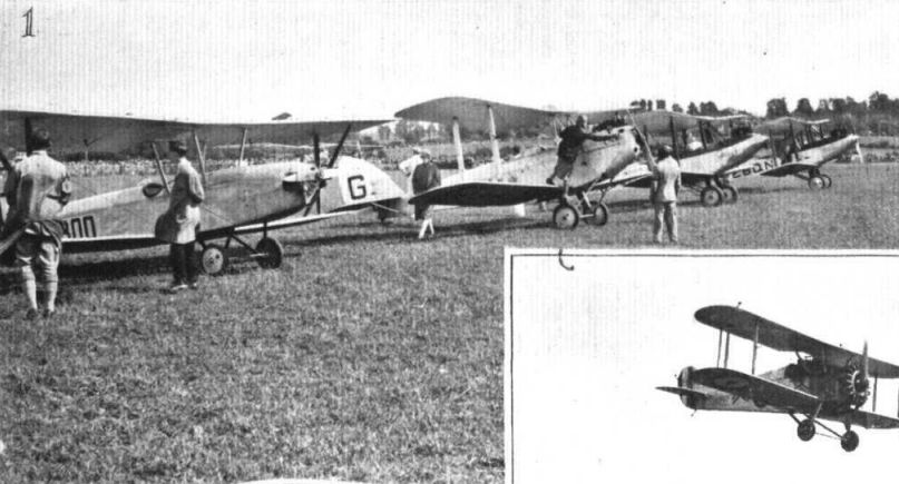
Регистрационный номер: G-EBOO [23] THE BRISTOL FLYING .MEETING: 1, Line-up for the Final of the First Handicap Race. The machines include, from left to right, the Halton "Mayfly," Lady Bailey's "Moth" PU, Watt's "Avian," QL, and the Farnborough Club "Avian," ON.
Другие самолёты на фотографии: Avro Avian / Type 594/616 - Великобритания - 1926De Havilland Moth / D.H.60 - Великобритания - 1925
-
Flight 1927-10 / Flight
Регистрационный номер: G-EBOO [23] SHERBURN AIR PAGEANT: (1) This shows the line up for the President's Light Aeroplane Handicap;
-
Aeroplane Monthly 1974-08 / C.Latimer-Needham - The Halton aeroplanes
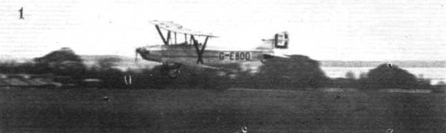
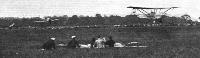
Регистрационный номер: G-EBOO [23] DAVID AND GOLIATH: Considerable amusement was caused at Bournemouth on Whit Monday by a heat in which the Halton "Mayfly" (30-h.p. Bristol "Cherub") (shown) was racing against the Vickers "Vixen III" (500 h.p. Napier "Lion").
-
Aeroplane Monthly 1974-08 / C.Latimer-Needham - The Halton aeroplanes
Регистрационный номер: G-EBOO [23] The HAC1 Mayfly winning the Selfridge Cup, at the Bristol Air Pageant on June 22, 1927, piloted by Flt Lt le Poer Trench.
-
Aeroplane Monthly 1974-08 / C.Latimer-Needham - The Halton aeroplanes
Регистрационный номер: G-EBOO [23] The Mayfly at Bournemouth on June 4-6, 1927, with the forward cockpit faired over.
-

Flight 1927-05 / Flight
Регистрационный номер: G-EBOO [23] THE HAMPSHIRE AIR PAGEANT: The first two home, who were, however, disqualified - Uwins on the Bristol "Brownie" and Le Poer Trench on "Halton I"
Другие самолёты на фотографии: Bristol Brownie / Type 91 - Великобритания - 1924
-

Flight 1927-09 / Flight
Регистрационный номер: G-EBOO [23] HOOTON AIR PAGEANT: (1) Flt. Lt. Le Poer Trench winning the Inter-Club Members' Race on the H.A.C.I.
-
Air-Britain Archive 1985-03 / British Flying Schools 1927-8
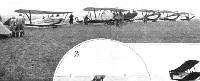
Регистрационный номер: G-EBOO [23] THE BRISTOL AIR PAGEANT: A portion of the "Parade." Nearest the camera is a de Havilland "Cirrus-Moth." Ahead of that a Westland "Cirrus-Widgeon," an Avro "Cirrus-Avian" and a Blackburn "Genet-Bluebird." (S.E.5 ???)
A collection of flying school aircraft at a meeting, probably in April or May 1928. From left to right we have G-EBXG DH.60X Moth with Handley Page auto slots which was to be used by the Nottingham Flying Club; G-EBSN another DH.60X of the Bristol & Wessex Aero Club; G-EBRO a Westland Wigeon 3; G-EBVU an Avro Avian 3 purchased about this time by Capt Henry D.Wolff; an SE.5A G-EBIB; G-EBOO the Halton Aero Club Mayfly; and G-EBJT a Westland Widgeon 2.Другие самолёты на фотографии: Avro Avian / Type 594/616 - Великобритания - 1926De Havilland Gipsy Moth / Moth X - Великобритания - 1928De Havilland Moth / D.H.60 - Великобритания - 1925RAF S.E.5 - Великобритания - 1916Westland Widgeon - Великобритания - 1924


-
Aeroplane Monthly 1974-08 / C.Latimer-Needham - The Halton aeroplanes
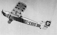
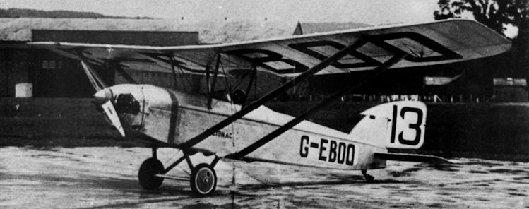
Регистрационный номер: G-EBOO [23] HALTON H.A.C.1: Amateur-built Light Plane, with 30 h.p. Bristol "Cherub" Engine.
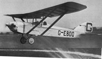
The Minus at Bristol Air Pageant, May 5, 1928. Note the unfaired struts and absence of a spinner. -
Aeroplane Monthly 1974-08 / C.Latimer-Needham - The Halton aeroplanes
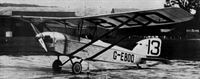
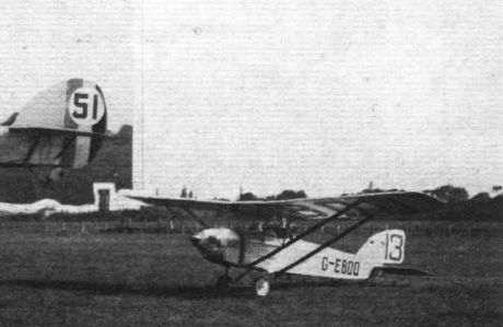
Регистрационный номер: G-EBOO [23] The No 13 proved unlucky for the Minus in the 1929 King’s Cup Race.
-

Flight 1929-07 / Flight
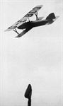
Регистрационный номер: G-EBOO [23] EXTREMES: Limit man Flight.-Lieut. G. R. Ashton on the H.A.C.2 "Minus" (Bristol "Cherub") starting from Heston
-
Aeroplane Monthly 1974-08 / C.Latimer-Needham - The Halton aeroplanes
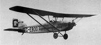
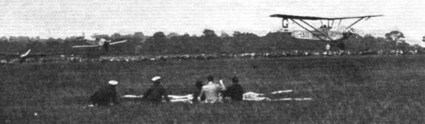
Регистрационный номер: G-EBOO [23] The Halton monoplane H.A.C.2 "Minus" (31-h.p. Bristol "Cherub III") landing in the circle, flown by Flight-Lieut. Le Poer Trench.
A fine view of Flt Lt Le Poer Trench in the Minus at the Cambridge Aero Club's display, June 10-11, 1929. -
Aeroplane Monthly 1974-08 / C.Latimer-Needham - The Halton aeroplanes
Регистрационный номер: G-EBOO [23] The HAC2 Minus with streamlined struts and a spinner added.
-
Aeroplane Monthly 1974-08 / C.Latimer-Needham - The Halton aeroplanes
Регистрационный номер: G-EBOO [23] The Minus during its appearance with the RAF "new types" at the 1928 Hendon Display.
-
Flight 1928-05 / Flight
Регистрационный номер: G-EBOO [23] WAKEFIELD HANDICAP: Flt.-Lieut. Le Poer Trench on the Halton monoplane "OO," leading Flt.-Lieut Soden on his D.H. "Moth" (Genet) "OU" in the second lap of the race, which was eventually won by the former at 80 1/2 m.p.h.
Другие самолёты на фотографии: De Havilland Genet Moth - Великобритания - 1926


-
Flight 1927-02 / Flight
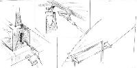
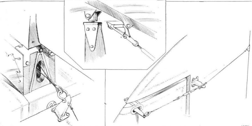
SOME CONSTRUCTIONAL DETAILS OF THE HALTON H.A.C.1 "MAYFLY": Above, the attachment of a lift wire and of the ends of the interplane X-strut to the top spar. On the left, the sternpost of the fuselage, showing how elevator control cables pass direct into the body and on to the control stick. On the right, the rudder cranks, those projecting through the fin being mounted on a vertical lay shaft.
-
Flight 1926-09 / Flight
Halton H.A.C.1 Bristol "Cherub" Engine

- Фотографии