
 Wiki
Wiki Варианты
- Short - Empire / S.23 - 1936 - Великобритания
- Short - Mayo Composite (S.20 Mercury and S.21 Maia) - 1938 - Великобритания
- Short - S.26 G-class - 1939 - Великобритания
S.26 G-class
Short S.23, S.30 и S.33 Empire
<...>
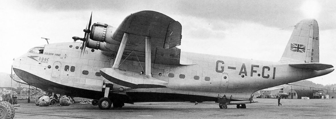
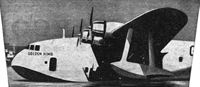
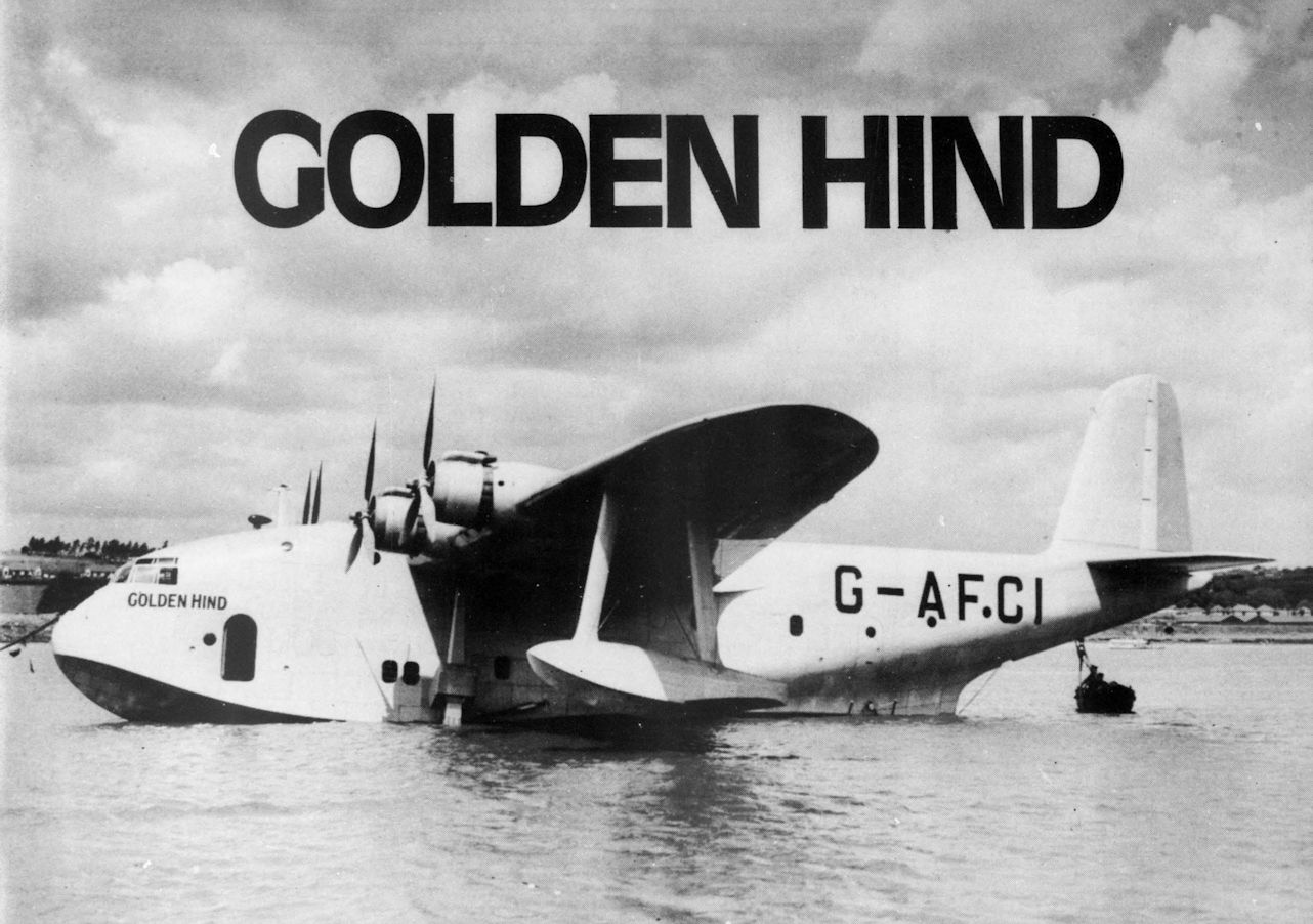
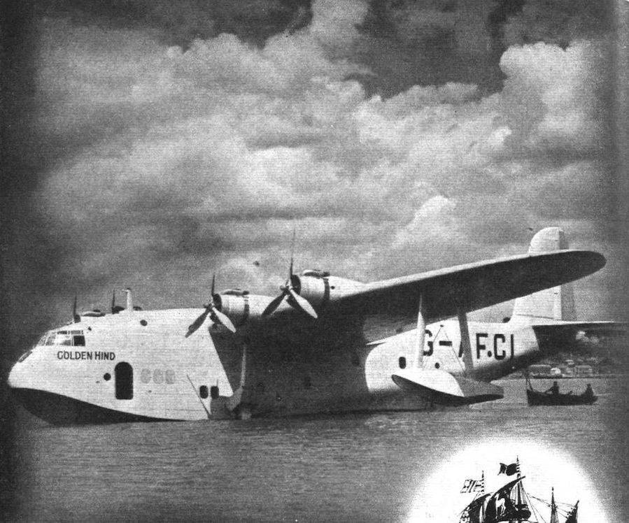
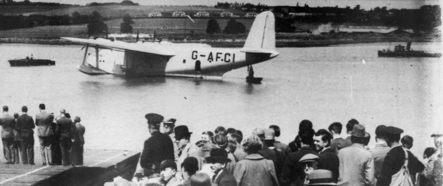
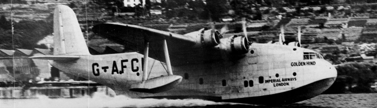
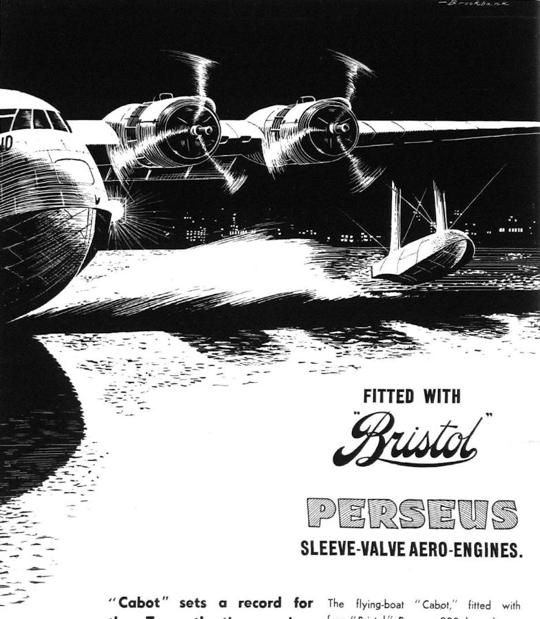
Компания также построила три летающие лодки S.26, заказанные "Imperial Airways" для беспосадочных трансатлантических перелетов с целью доставки почты. Они были крупнее летающих лодок класса "C" и оснащались двигателями Bristol Hercules мощностью 1380 л. с. Первая такая летающая лодка, получившая название "Golden Hind", была облетана в июне 1939 года. Новые самолеты стали известны как летающие лодки класса "G", и в годы войны все они были реквизированы для использования в качестве морских разведывательных в составе британских ВВС.
В июне 1941 года была уничтожена летающая лодка "Golden Fleece", чуть позже в том же году две оставшиеся S.26 передали компании BOAC, где они использовались в качестве 40-местных пассажирских самолетов. 9 января 1943 года лодка "Golden Horn" разбилась на реке Тагус в Португалии после того, как возник пожар в силовой установке. В последние годы войны оставшаяся лодка "Golden Hind" совершала коммерческие рейсы между Момбасой и Цейлоном, а после войны - между Пул-Харбором и Каиром. В мае 1954 года она затонула во время шторма.
Описание:
- S.26 G-class
- Flight, July 1939
THE BIGGEST SHORT - Flight, November 1939
Britain's Civil Aircraft
Фотографии

-

Мировая Авиация 215
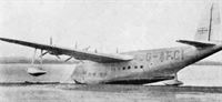
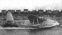
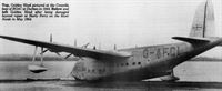
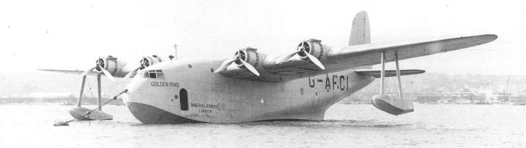
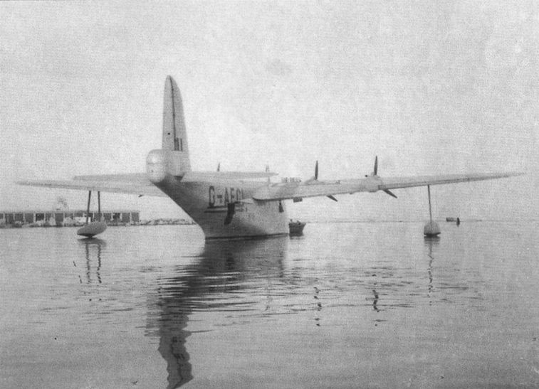
Регистрационный номер: G-AFCI [38], X8275 [38] Три лодки "G"-класса по размерам значительно превосходили лодки "C"-класса и оснащались моторами Hercules. Первой стала лодка "Golden Hind", она единственная из всего "G"-класса пережила войну. Снимок сделан после войны, когда "Golden Hind" эксплуатировалась в авиакомпании BOAC.
-

Aeroplane Monthly 1982-12 / R.Riding - Golden Hind
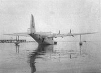
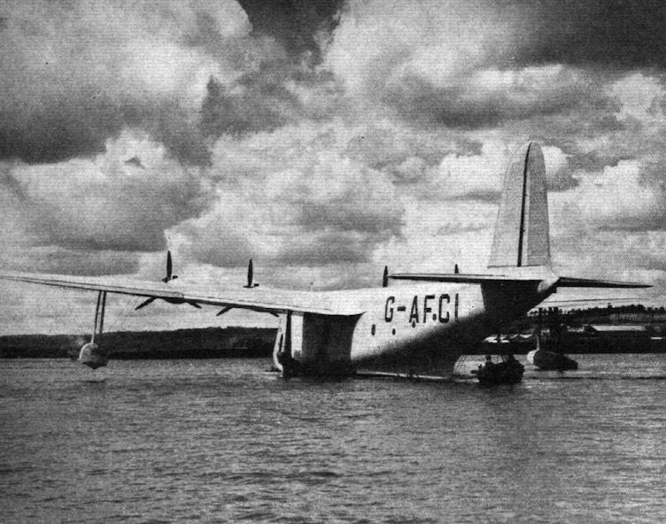
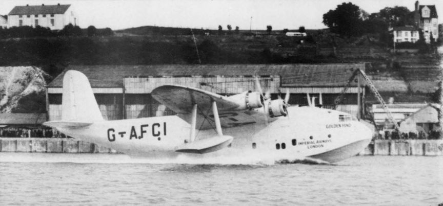
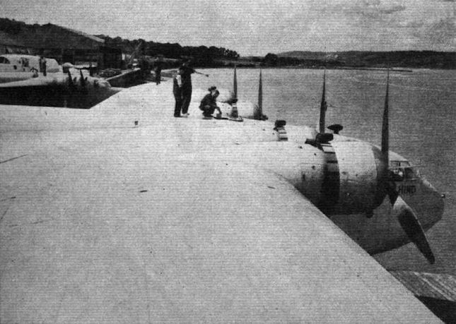
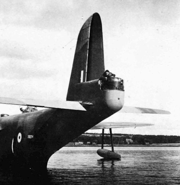
Регистрационный номер: G-AFCI [38], X8275 [38] The rear step of the “G” class boats is similar to that which has been found so successful on the Sunderland military boats. When this picture was taken the beaching trolley had not been dropped.
Golden Hind photographed on June 17, 1939 on the Medway, the day of her launching. -
Flight 1939-08 / Flight Advertisements
Регистрационный номер: G-AFCI [38], X8275 [38] -

Air Enthusiast 1996-05 / Round-Out
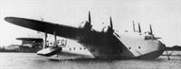
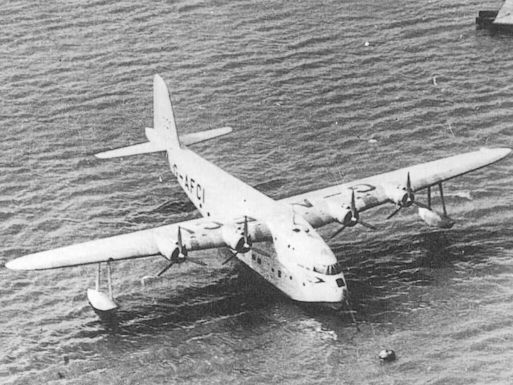
Регистрационный номер: G-AFCI [38], X8275 [38] View of Short ‘G-Boat’ G-AFCI ‘Golden Hind'. Extant until the mid-1950s, it nearly survived into a time when it would have been preserved.
-
Jane's All the World Aircraft 1980 / Encyclopedia of Aviation - Aircraft A-Z - v5
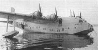
Регистрационный номер: G-AFCI [38], X8275 [38] Short G-class Golden Hind.
-
Flight 1939-07 / Flight Advertisements
Регистрационный номер: G-AFCI [38], X8275 [38] -

Aeroplane Monthly 1982-12 / R.Riding - Golden Hind
Регистрационный номер: G-AFCI [38], X8275 [38] Another picture taken on the day of Golden Hind’s launching on June 17, 1939.
-
Air-Britain Archive 1992-01
Регистрационный номер: G-AFCI [38], X8275 [38] A photo from Flight of 14.5.54 showing G-AFCI "Golden Hind" up against the causeway at Harry Ferry,
-

Flight 1939-07 / Flight
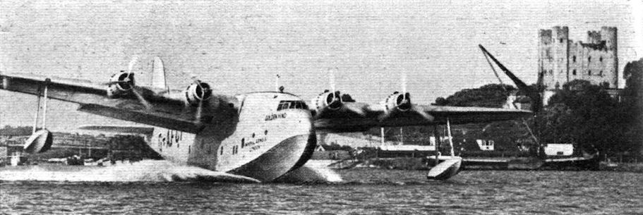
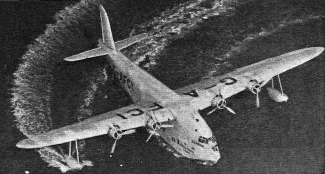
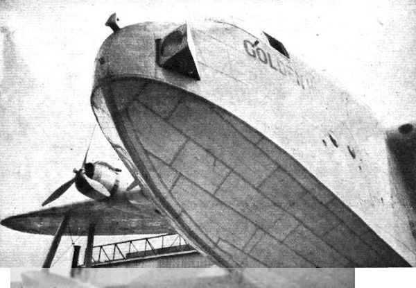
Регистрационный номер: G-AFCI [38], X8275 [38] The size of Golden Hind is such as to dwarf the four big Bristol Hercules engines. The wing-tip floats are set proportionately farther out towards the tips than on earlier types.
-
Aeroplane Monthly 1992-01 / Personal album. Civil
Регистрационный номер: G-AFCI [38], X8275 [38] Short S.26 G-AFCI Golden Hind taken at Augusta, Sicily on July 10, 1945 enroute for the UK for the last time after overseas service. Golden Hind survived until March 1954, when it was damaged beyond repair at Harty Ferry on the River Swale.
-
Aeroplane Monthly 1982-12 / R.Riding - Golden Hind
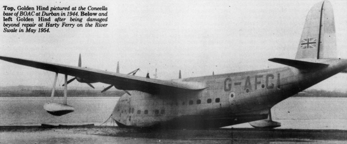
Регистрационный номер: G-AFCI [38], X8275 [38] Golden Hind pictured at the Coneella base of BOAC at Durban in 1944.
-
Aeroplane Monthly 1992-01 / Personal album. Civil
Регистрационный номер: G-AFCI [38], X8275 [38] Short S.26 G-AFCI Golden Hind taken at Augusta, Sicily on July 10, 1945 enroute for the UK for the last time after overseas service. Golden Hind survived until March 1954, when it was damaged beyond repair at Harty Ferry on the River Swale.
-
Air-Britain Archive 1984-03 / Impressment Review (18)
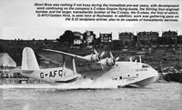
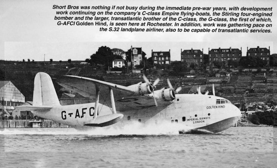
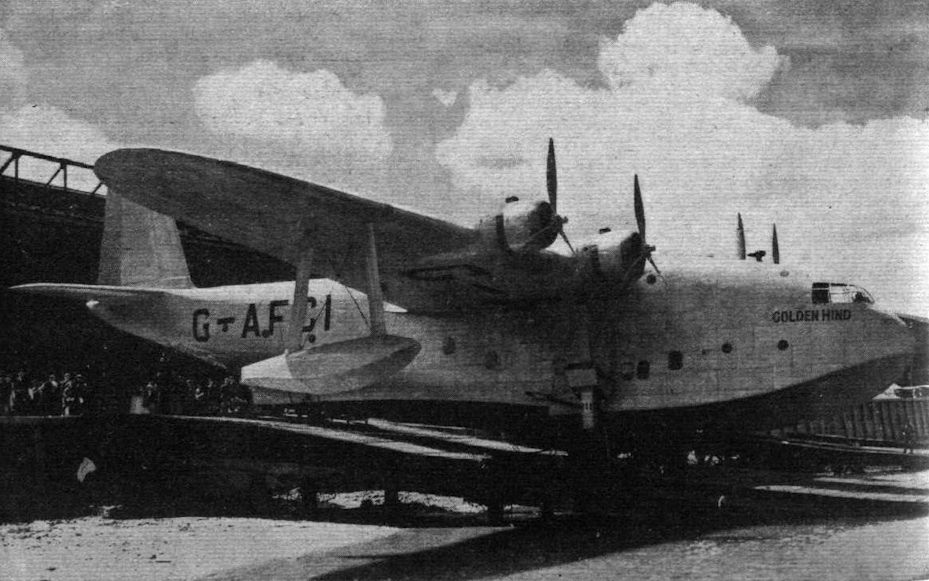
Регистрационный номер: G-AFCI [38], X8275 [38] Short Bros was nothing if not busy during the immediate pre-war years, with development work continuing on the company’s C-class Empire flying-boats, the Stirling four-engined bomber and the larger, transatlantic brother of the C-class, the G-class, the first of which, G-AFCI Golden Hind, is seen here at Rochester. In addition, work was gathering pace on the S.32 landplane airliner, also to be capable of transatlantic services.
-
Aeroplane Monthly 1974-05 / P.Moss - Wings for the Empire (5)
Регистрационный номер: G-AFCI [38], X8275 [38] Short S.26 “G” class flying boat G-AFCI Golden Hind shortly after launch at Rochester on July 21, 1939.
-
Aeroplane Monthly 1982-12 / R.Riding - Golden Hind
Регистрационный номер: G-AFCI [38], X8275 [38] -
АвиаМастер 2005-08 / А.Харук - "Летающий отель" с глубинными бомбами /Монография/
Регистрационный номер: G-AFCI [38], X8275 [38] Этот Шорт "Солент" был назван Golden Hind - "Золотая лань" в честь каравеллы знаменитого английского мореплавателя Френсиса Дрейка
-

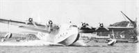
Flight 1939-07 / Flight
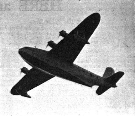
Регистрационный номер: G-AFCI [38], X8275 [38] THE G-BOAT takes the air - a Flight photograph at Rochester last Friday.
-
Aeroplane Monthly 1982-12 / R.Riding - Golden Hind
Регистрационный номер: G-AFCI [38], X8275 [38] Golden Hind lands after an uneventful first flight on July 21, 1939 in the hands of John Parker.
-
Flight 1939-07 / Flight
Регистрационный номер: G-AFCI [38], X8275 [38] FLEDGED: The short G-class boat Golden Hind touching down on the Medway last Friday after her first flight - an entirely successful one of 16 minutes. Mr. J. Lankester Parker, with Flt. Lt. E. Moreton as assistant pilot and Mr. George Cotton (chief engineer) as a passenger, made the test.
-

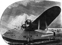
Flight 1939-11 / Flight
Регистрационный номер: G-AFCI [38], X8275 [38] Golden Hind, first of the Short 'G' class flying boats fitted with four Bristol Hercules sleeve-valve engines.
-

Air Enthusiast 1996-05 / Round-Out
Регистрационный номер: G-AFCI [38], X8275 [38] View of Short ‘G-Boat’ G-AFCI ‘Golden Hind'. Extant until the mid-1950s, it nearly survived into a time when it would have been preserved.
-
Flight 1939-07 / Flight
Регистрационный номер: G-AFCI [38], X8275 [38] Some of the 2,160 sq. ft. of wing area is shown in this view, which suggests that while the boat is at moorings the passengers - trained to walk in the right places - might get plenty of exercise by promenading.
-
Flight 1939-07 / Flight Advertisements
Регистрационный номер: G-AFCI [38], X8275 [38] -

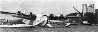
Flight 1939-06 / Flight
Регистрационный номер: G-AFCI [38], X8275 [38] SHORT’S LATEST: The Golden Hind was launched at Rochester last Saturday. This 32-ton craft, the first of the “G” class, will be used for mail carrying only, and will have a range of more than 3,000 miles. The most noticeable difference from the Empire boats, apart from size, lies in the shape of the rear step. Four Bristol Hercules provide the power.
-

Aeroplane Monthly 1974-05 / P.Moss - Wings for the Empire (5)
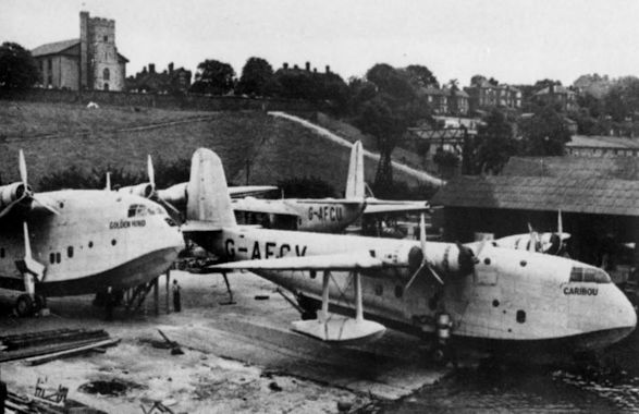
Регистрационный номер: G-AFCI [38], X8275 [38] Three Short ’boats at Rochester: G-AFCI Golden Hind, G-AFCU Cabot, and G-AFCV Caribou.
Другие самолёты на фотографии: Short Empire / S.23 - Великобритания - 1936
-

Aeroplane Monthly 1990-04 / R.Moulton - Last 'boat to Durban
Регистрационный номер: G-AFCI [38], X8275 [38] The demilitarized Golden Hind having its Hercules engines changed at Congella in January 1945, framed by Cambria.
-
Flight 1939-06 / Flight
Регистрационный номер: G-AFCI [38], X8275 [38] UP-TO-THE-MINUTE: In this issue of Flight is told the story of Imperial Airways and its flying equipment from the earliest days. Here is the very latest addition to its marine aircraft fleet - the Golden Hind, first of the three 32-ton "G"-class boats, fitted with four Bristol Hercules engines each. She is seen almost ready for her launching this week.
-
Aeroplane Monthly 1982-12 / R.Riding - Golden Hind
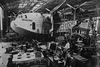
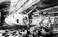
Регистрационный номер: G-AFCI [38], X8275 [38] Golden Hind nearing completion at Rochester on June 9, 1939. With a wing span of 134ft 4in she was the largest boat to emerge from no 3 Shop.
-
Aeroplane Monthly 1982-12 / R.Riding - Golden Hind
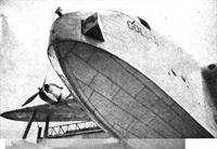
Регистрационный номер: G-AFCI [38], X8275 [38] Exterior view of the Rotax-Harley retractable searchlight in the nose. Teleflex controls give the beam elevating and traversing movement. The view, incidentally, gives a good idea of the bottom plating.
Unusual view of Golden Hind on the launching slipway on June 17, 1939. Note the retractable landing light in the nose. -
Flight 1939-07 / Flight
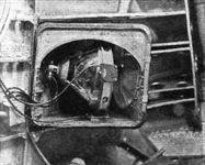
Регистрационный номер: G-AFCI [38], X8275 [38] Interior view of the Rotax-Harley retractable searchlight in the nose. Teleflex controls give the beam elevating and traversing movement.
-
Flight 1939-07 / Flight Advertisements
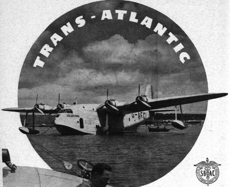
THE LARGEST BRITISH FLYING BOATS Golden Hind, Grenadier and Granville, now being completed by SHORT BROS., LTD. at Rochester for IMPERIAL AIRWAYS’ trans-Atlantic services, are each equipped with 5.500 ft. of Callender Aircraft Cable.
-

Air-Britain Aeromilitaria 1997-03 / Picture pages
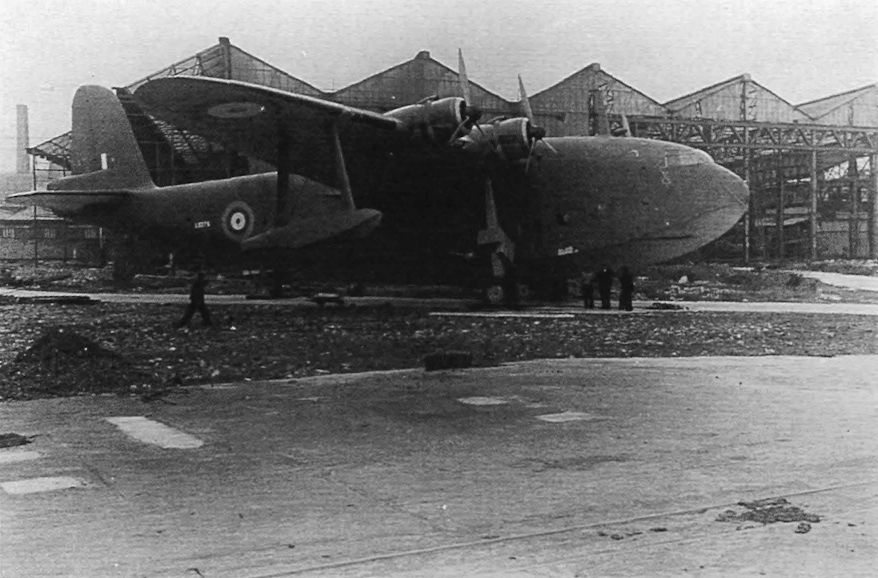
Регистрационный номер: X8275 [38], G-AFCI [38] Peter Berry has sent in this laser print of X8275 Golden Hind. This Short S.26 was built for Imperial Airways as G-AFCI and impressed. The original was noted 'Caird's Shipyard', at Greenock on the Clyde and was probably taken in February 1941 when X8275 was there for maintenance. Greenock was a MU run by Scottish Aviation.
-

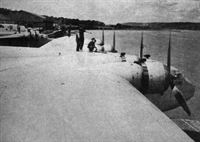
Air-Britain Aeromilitaria 1981-02 / Arming the G-boats
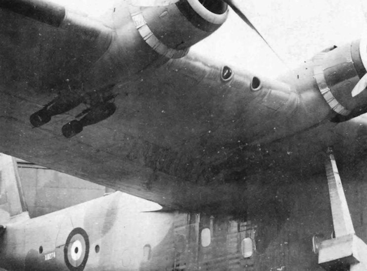
Регистрационный номер: X8274 [2] Twin bombracks were fitted under each engine nacelle
-
Air-Britain Aeromilitaria 1981-02 / Arming the G-boats
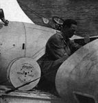
The forward Boulton-Paul turret mounted between the main spars. This turret was mounted centrally in contrast with the after turret which was offset to starboard, permitting the fitment of four ASV masts without completely fouling the field of fire.
-
Air-Britain Aeromilitaria 1981-02 / Arming the G-boats
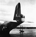
Регистрационный номер: X8274 [2] Close-up of the modified tail position and its fairing
-
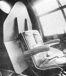
Flight 1939-07 / Flight
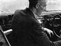
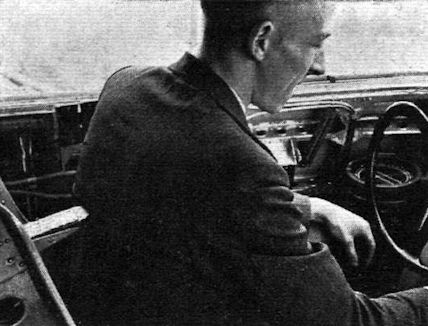
“Unlock controls before taking off” says the label on the uncomfortable-looking device poking into the pilot’s back. Until they are unlocked the device remains in this aggressive position.
-
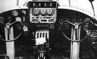
Flight 1939-07 / Flight
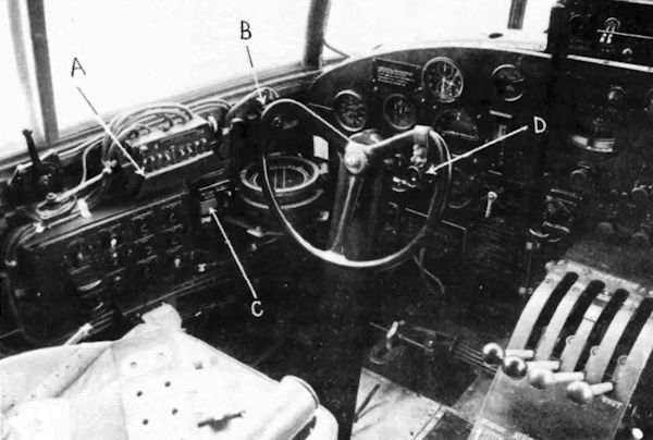
Регистрационный номер: G-AFCI [38], X8275 [38] As will be seen in this photograph taken in the partially finished Golden Hind, the control and instrument layout of the “G” class boat is very similar to that of the Empire type. One really noticeable difference is the fact that only the essential engine instruments are to be found on the right-hand side of the dashboard, the others being mounted in the engineer's own instrument panel at the rear of the navigation compartment.
-

Air-Britain Aeromilitaria 1981-02 / Arming the G-boats
Captain's position showing the bomb release controls and selector box (A)
-
Aeroplane Monthly 1982-12 / R.Riding - Golden Hind
A G-Class boat flight deck during construction.
-
Air-Britain Aeromilitaria 1981-02 / Arming the G-boats
The pilot's seat was protected by a slab of armour plate
-
Flight 1939-07 / Flight
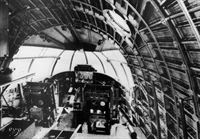
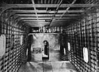
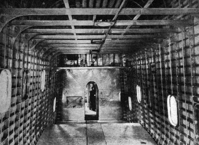
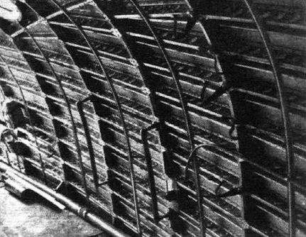
View inside the hull of a “G” boat, showing not only the spaciousness but the general type of construction.
-
Air-Britain Aeromilitaria 1981-02 / Arming the G-boats
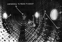
A long, long trail awinding to the rear turret (D and A), racks for flares and smoke-floats (B and C) and the flare chute (E).
-

Flight 1939-07 / Flight
The Z-section stringers are stabilised, midway between main frames, by shallow channel-section strips, as shown in this photograph.
-
Aeroplane Monthly 1982-12 / R.Riding - Golden Hind
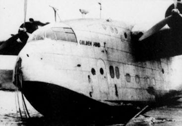
Регистрационный номер: G-AFCI [38], X8275 [38] Golden Hind after being damaged beyond repair at Harty Ferry on the River Swale in May 1954.
-

Aeroplane Monthly 1982-12 / R.Riding - Golden Hind
Регистрационный номер: G-AFCI [38], X8275 [38] Golden Hind after being damaged beyond repair at Harty Ferry on the River Swale in May 1954.
-

Flight 1939-12 / Flight Advertisements
Регистрационный номер: G-AFCI [38], X8275 [38] -
Flight 1939-07 / Flight Advertisements
Регистрационный номер: G-AFCI [38], X8275 [38] -
Flight 1939-04 / Flight
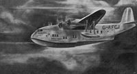
Регистрационный номер: G-AFCJ GOLDEN HIND: A Flight drawing anticipating the appearance of the Golden Hind, one of the three Short “G” Class flying boats for Imperial Airways. She will be considerably longer than her Elizabethan namesake and will weigh rather more than 32 tons. Drake's vessel was probably of about 100 tons. Note that the rear step follows Sunderland practice rather than Empire boat design. The engines are four Bristol Hercules.
-
Flight 1939-07 / Flight Advertisements
Регистрационный номер: G-AFCI [38], X8275 [38] -
Flight 1939-07 / Flight
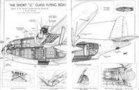
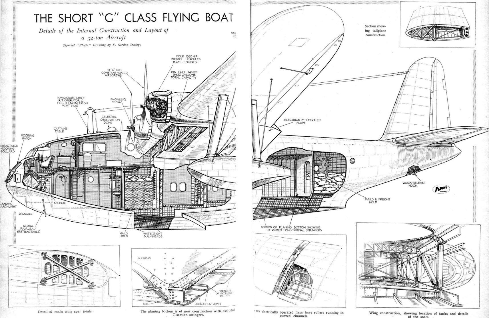
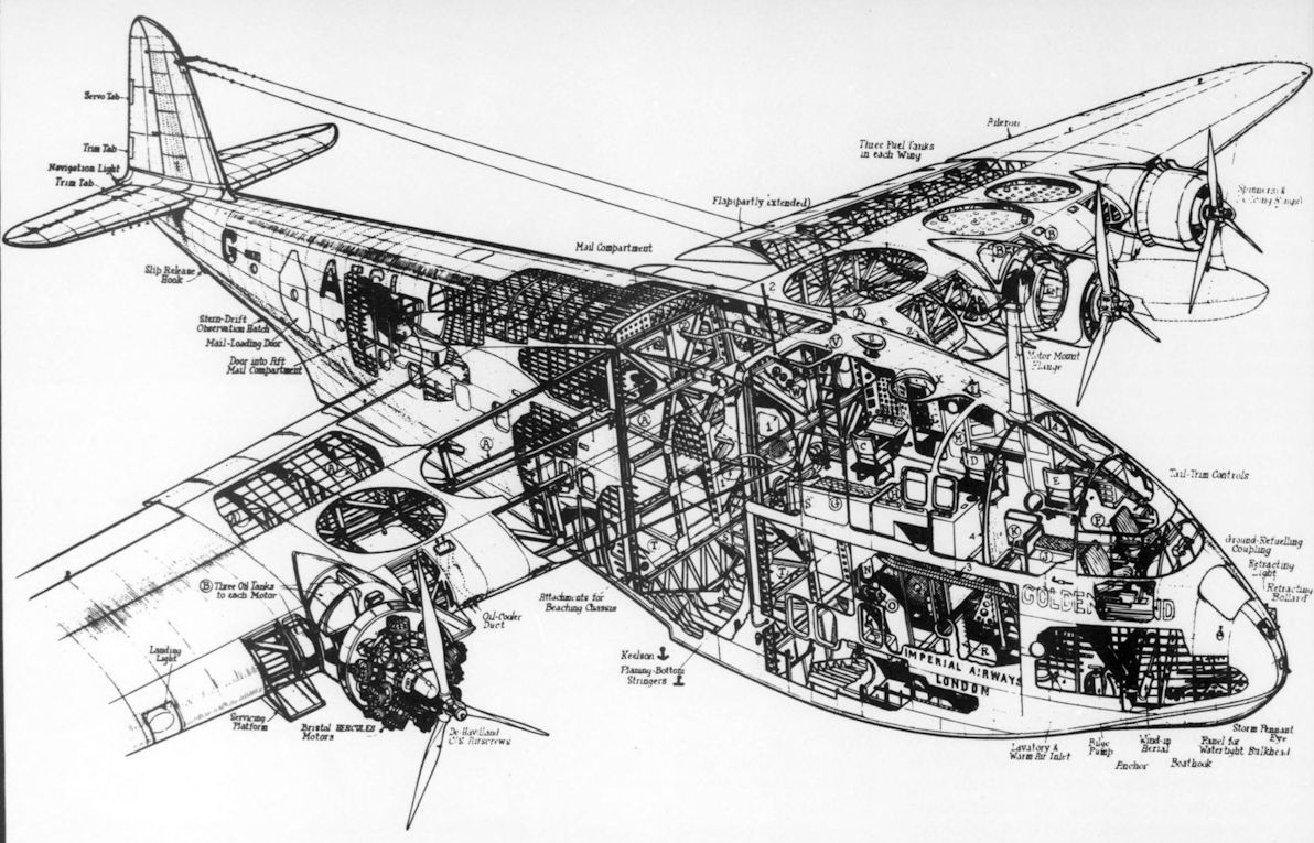
THE SHORT "G" CLASS FLYING BOAT. Details of the Internal Construction and Layout of a 32-ton Aircraft
-

-
Air-Britain Aeromilitaria 1981-02 / Arming the G-boats
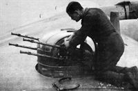
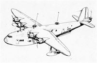
Регистрационный номер: X8275 [38], G-AFCI [38] Armament of the G-boats consisted of three Boulton-Paul BPA Mk.II four-gun turrets; A - on the centreline between the wing spars; B offset to starboard and C on a new extension built in the tail cone.
-

Flight 1939-07 / Flight
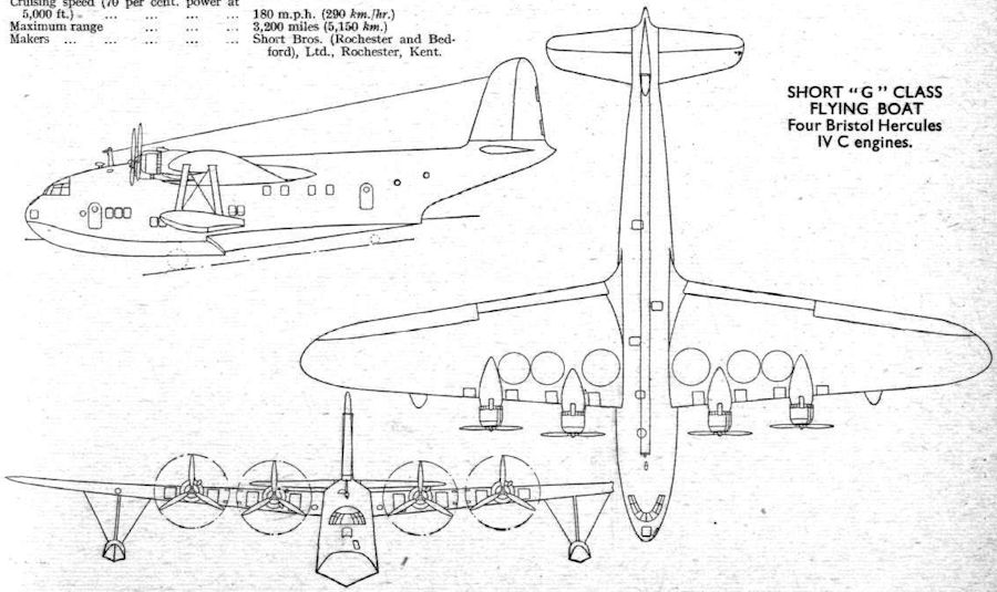
SHORT "G” CLASS FLYING BOAT. Four Bristol Hercules IV C engines.
-
Aviation Historian 34 / R.Pegram - BOAC & the Brabazon committee
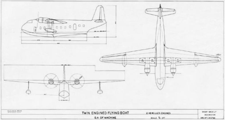
Essentially a development of Short Bros’ tried-and-trusted pre-war Empire flying-boats, the company’s “Short-Medium Range Civil Flying Boat” was presented in a brochure in February 1945, to be fitted with a pair of Bristol Hercules engines. It was already becoming increasingly clear, however, that the flying-boat era was over.


- Фотографии