
 Wiki
Wiki 
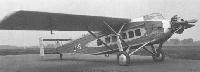
Vickers Type 121 Wibault
<...>
Чуть больше повезло транспортному подкосному высокоплану Vickers Viastra, в котором использовался тот же тип конструкции. Прототип Type 160 Viastra I, оснащенный тремя Armstrong Siddeley Lynx Major мощностью 270 л.с„ облетали 1 октября 1930 года.
От авиакомпании «West Australian Airways» был получен заказ на три 12-местных самолета, первые два из которых получили обозначение Type 198 Viastra II и были оснащены двумя двигателями Bristol Jupiter XIF мощностью 525 л. с., а построенный в единственном экземпляре самолет Type 203 Viastra VI получил один двигатель Jupiter XIF. Однако позже заказ на Viastra VI был отменен.
Название Type 199 Viastra III было присвоено первому опытному самолету после того, как на него установили два двигателя Armstrong Siddeley Jaguar VIC, а впоследствии, когда он был оснащен тремя двигателями Jupiter VIFM, самолет получил обозначение Type 220 Viastra VIII. Последним представителем семейства стал единичный Type 259 Viastra X с двумя двигателями Bristol Pegasus, построенный для Принца Уэльского. Он был облетан в апреле 1933 года и с 1935 года использовался Министерством авиации для испытаний радиосвязного оборудования. Самолет был списан в 1937 году.
Описание:
- Vickers Type 121 Wibault
- Flight, June 1930
THE VICKERS "VIASTRA" - Flight, September 1930
VICKERS "VIASTRA I" - Flight, June 1931
SPECIAL TYPES AT THE DISPLAY
Фотографии

-
Flight 1930-09 / Flight
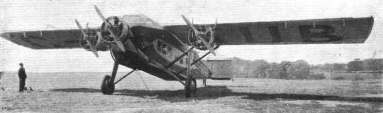
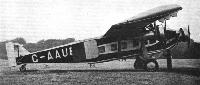
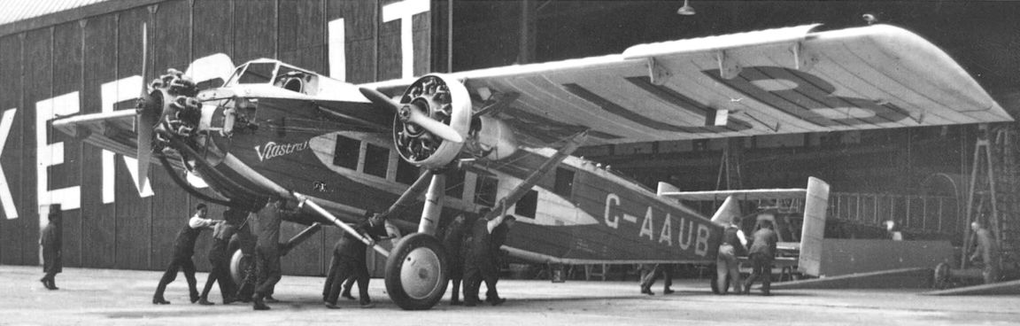
Регистрационный номер: G-AAUB [10] THE VICKERS LYNX "VIASTRA I": In the three-quarter front view, the Townend rings around the engines may be clearly seen.
-

Aeroplane Monthly 1989-08 / J.Stroud - Wings of Peace
Регистрационный номер: G-AAUB [10] Front view of the Viastra I.
-
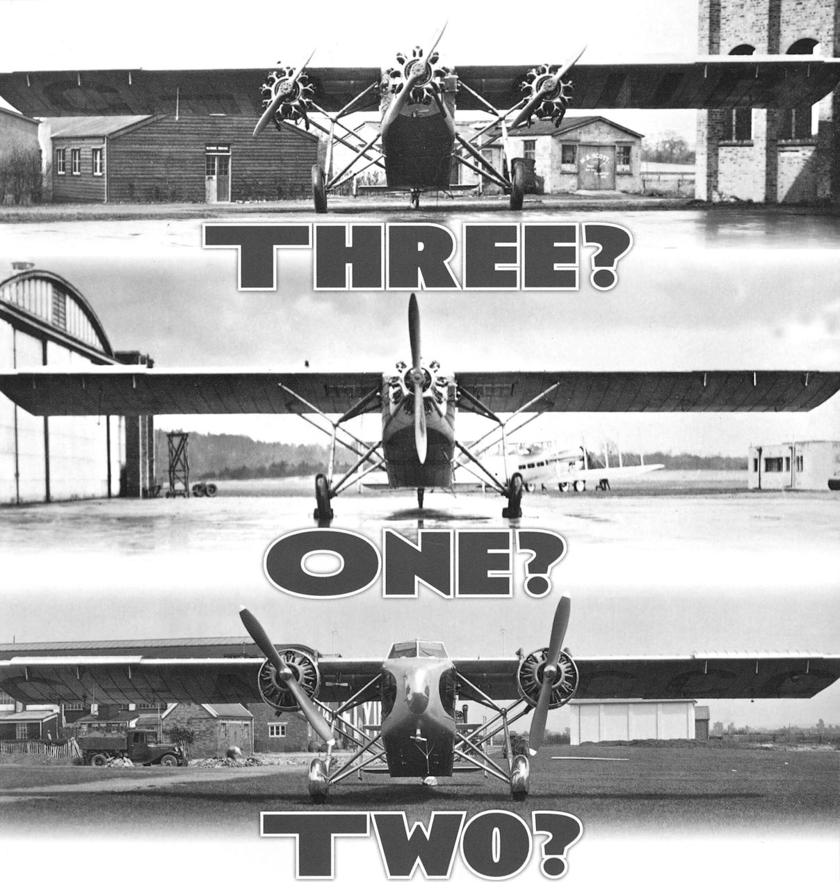
Air Enthusiast 2006-05 / A.Ord-Hume - Three? One? Two? /Airliners and air services/
Регистрационный номер: G-AAUB [10] Viastra I G-AAUB seen after conversion to Type 220, with three Jupiter VIFMs, the outer ones fitted with Townend rings. Note the long exhaust pipes to the nose engine, and the triangular fin.
-
Flight 1930-09 / Flight
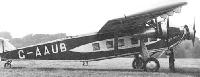
Регистрационный номер: G-AAUB [10] THE VICKERS LYNX "VIASTRA I": Three-quarter rear view.
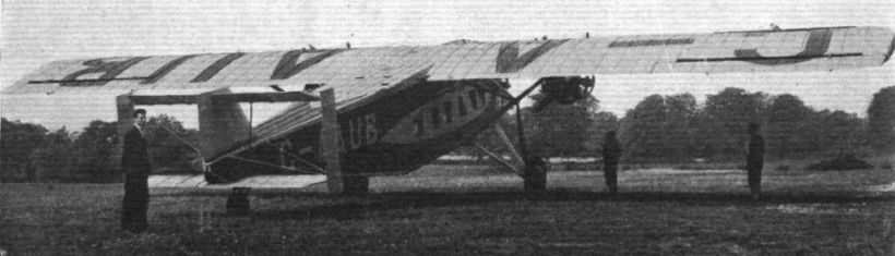
Rear view of the Viastra I. Note the different angles of the horizontal tail surfaces and the wrongly painted registration. The aircraft first flew on October 1, 1930. -
Flight 1930-09 / Flight
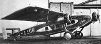
Регистрационный номер: G-AAUB [10] THE VICKERS LYNX " VIASTRA I": Side view.
-
Air Enthusiast 2006-05 / A.Ord-Hume - Three? One? Two? /Airliners and air services/
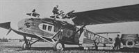
Регистрационный номер: G-AAUB [10] The Mk.I, now as a Type 220 Mk.VIII, fitted with three Bristol Jupiter VIFMs. The wing-mounted engines are slung lower than in earlier versions.
-
Air Enthusiast 2006-05 / A.Ord-Hume - Three? One? Two? /Airliners and air services/
Регистрационный номер: G-AAUB [10] The Mk.l with three Jupiters but without Townend rings.
-
Flight 1930-09 / Flight
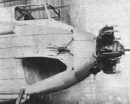
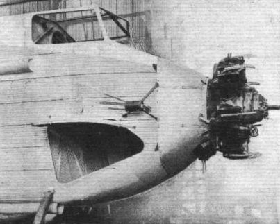
NEARING COMPLETION: In this photograph, taken before the machine was finished, may be seen the central engine (Lynx), forward luggage compartment, and windscreening of cockpit.


-
Flight 1933-12 / Flight
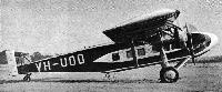
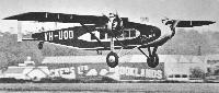
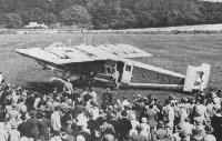
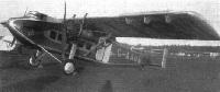
Регистрационный номер: VH-UOO [6] SUBSIDISED: One of the Vickers "Viastras" (two "Jupiters") used by West Australian Airways on the Perth - Adelaide service.
-

Aeroplane Monthly 1989-08 / J.Stroud - Wings of Peace
Регистрационный номер: VH-UOO [6] WAA’s Viastra II VH-UOO, with strut-mounted upper tail surface.
-

Air Enthusiast 2006-05 / A.Ord-Hume - Three? One? Two? /Airliners and air services/
Регистрационный номер: VH-UOO [6] The first Type 198 Viastra Mk.II in Australian markings as VH-UOO at Brooklands in 1930 before shipment to Fremantle.
-

Aeroplane Monthly 1989-08 / J.Stroud - Wings of Peace
Регистрационный номер: VH-UOO [6] West Australian Airways' Viastra II VH-UOO with triangular fin.
-
Air Enthusiast 2006-05 / A.Ord-Hume - Three? One? Two? /Airliners and air services/
Регистрационный номер: VH-UOO [6] First flight of Viastra II VH-UOO at Brooklands. Note the triangular fin is uncovered and is merely a pylon to support the elevators.
Viastra II, VH-UOO, on trials in the UK before being shipped to Australia in 1931. To improve performance, the Townend rings were removed in October 1932 and the slots in March 1934. -
Air Enthusiast 2006-05 / A.Ord-Hume - Three? One? Two? /Airliners and air services/
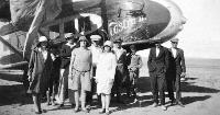
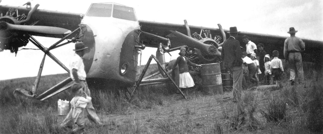
Регистрационный номер: VH-UOO [6] Passengers at Ceduna ready to board. Note that the engine covers are still on, as is the all important propeller cover.
-
Air International 1976-05 / Talkback
Регистрационный номер: VH-UOM [3] A rare photograph of Viastra II, VH-UOM, at Parafield, South Australia, in 1933. Note the nose landing-light and the unringed engines. Apparently this second WAA Viastra was delivered without wing slots.
-
Air Enthusiast 2006-05 / A.Ord-Hume - Three? One? Two? /Airliners and air services/
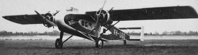
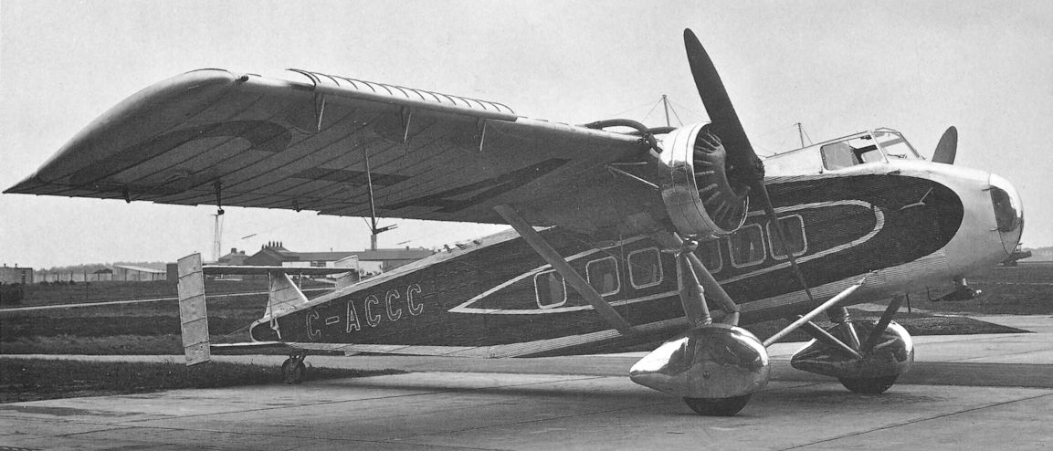
Регистрационный номер: G-ACCC [6] The Pegasus-powered G-ACCC at Tilton. A Bristol security officer standing next to it shows its scale.
-

Air Enthusiast 2006-05 / A.Ord-Hume - Three? One? Two? /Airliners and air services/
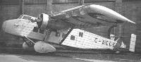
Регистрационный номер: G-ACCC [6] Этот G-ACCC - единственный построенный Viastra X, двухмоторный самолет для Принца Уэльского. Крыло имело размах 21,34 м и оснащалось большими закрылками.
G-ACCC in its finished livery, showing details of the Handley Page slots, engine mounting and Townend rings, as well as the curious linkages of the tail assembly. -

Aeroplane Monthly 1989-08 / J.Stroud - Wings of Peace
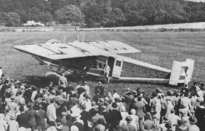
Регистрационный номер: G-ACCC [6] The Viastra X in Brigade of Guards’ colours, at Brooklands.
-
Aeroplane Monthly 1985-11 / A.Bennett - Fit for a king (1)
Регистрационный номер: G-ACCC [6] The Royal Vickers Viastra X.
-
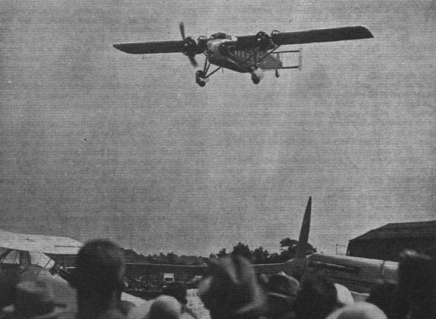
Flight 1934-07 / Flight
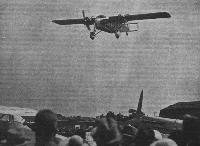
ICH DIEN": H.R.H. the Prince of Wales arriving at the R.A.F. Display in his Vickers "Viastra" (two Bristol "Pegasus" engines). It is to be hoped that the practical example set by the Prince will encourage considerable numbers of the 100,000 or so who saw his arrival at Hendon to make more extensive use of air travel.
-

Aeroplane Monthly 1989-08 / J.Stroud - Wings of Peace
Регистрационный номер: G-ACCC [6] The Viastra X at Croydon while being flown on experimental work by Imperial Airways.
-
Air Enthusiast 2006-05 / A.Ord-Hume - Three? One? Two? /Airliners and air services/
Регистрационный номер: G-ACCC [6] Before painting, G-ACCC reveals its somewhat snub nose, as well as the triangular fin.
-
Air Enthusiast 2006-05 / A.Ord-Hume - Three? One? Two? /Airliners and air services/
Регистрационный номер: G-AAUB [10] Prototype Viastra G-AAUB reengined as a twin to form the Type III, with low-mounted Jaguar VICs. Note the long drag strut to the rear lift strut.
-
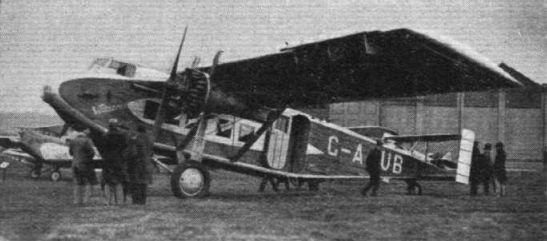
Flight 1931-01 / Flight
Регистрационный номер: G-AAUB [10] Fl.-Lt. P. W. S. Bulman flying the Vickers "Viastra," one of the latest British commercial aeroplanes, at Brooklands "India Demonstration."
-

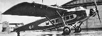
Flight 1930-11 / Flight
Регистрационный номер: G-AAUB [10] Vickers Viastra passenger carrier. Two Jaguars.


-
Air Enthusiast 2006-05 / A.Ord-Hume - Three? One? Two? /Airliners and air services/
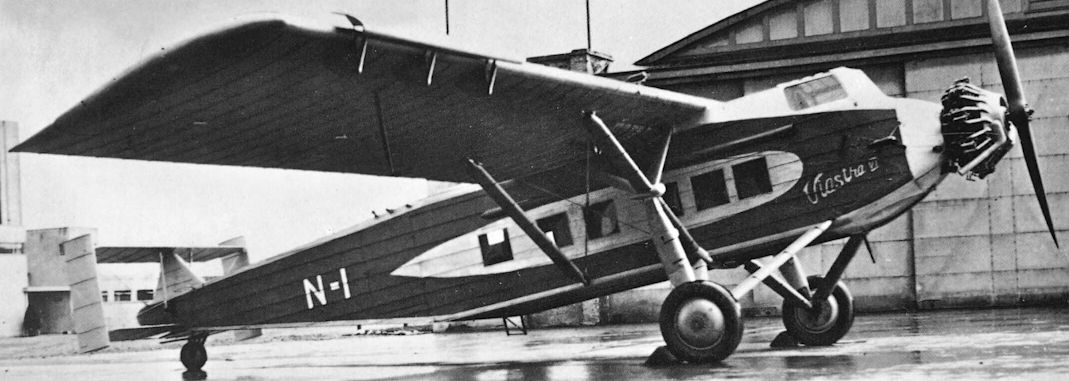
The Jupiter-powered Mk.VI with one Bristol IXF, with Supermarine's 'trade-plate' markings N-I. The two push-rods which operate the one-piece upper elevator are clearly shown either side of the triangular fin.
-

Aeroplane Monthly 1989-08 / J.Stroud - Wings of Peace
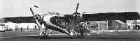
The single-engined Viastra VI at Brooklands. It was fitted with a 540 h.p. Bristol Jupiter radial.
-
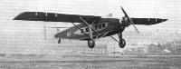
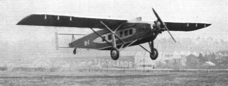
Flight 1931-05 / Flight
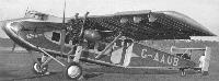
THE VICKERS SINGLE-ENGINED "VIASTRA": This machine has now been produced, according to the original plan, as a three-engined, twin-engined, and single-engined monoplane. West Australian Airways are using the twin-engined version on the Perth-Adelaide route. The single-engined type here shown landing at Brooklands is fitted with a Bristol "Jupiter" Series XI F.
-
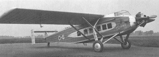
Air Enthusiast 2006-05 / A.Ord-Hume - Three? One? Two? /Airliners and air services/
The single-engined Mk.VI wearing the Vickers’ 'B Condition’ markings O-6.
-

Aeroplane Monthly 1989-08 / J.Stroud - Wings of Peace
The Vickers Viastra VI freighter flying at Brooklands.


-

-

Flight 1930-09 / Flight
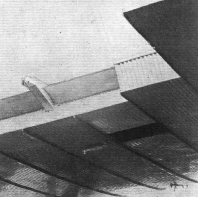
FOR THE FRISE AILERONS: Photograph showing brackets on which the ailerons are supported.
-
Flight 1930-09 / Flight
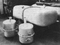
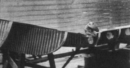
A NEW STYLE IN PETROL TANKS: In the "Viastra" Vickers use fuel tanks built up in two identical halves, joined in the centre by a flange coupling of novel design.
-

Flight 1930-09 / Flight
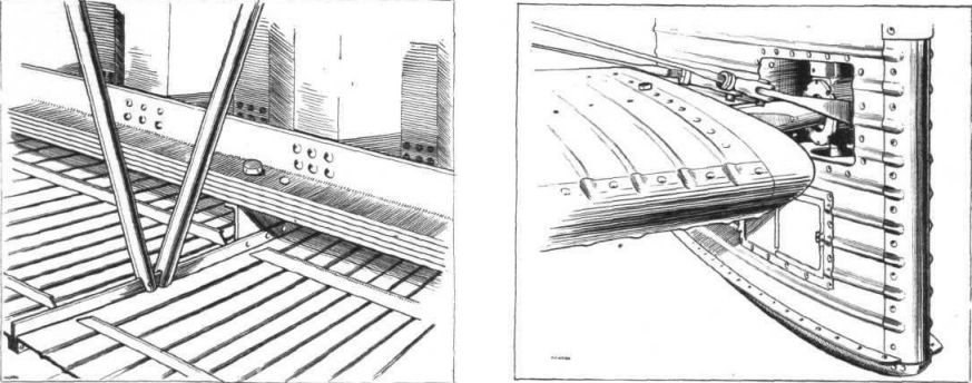
FUSELAGE DETAILS: This photograph shows the construction and placing of the formers which carry the cabin flooring. The fitting on the side is the anchorage for the radius rod of the undercarriage.
-
Flight 1930-09 / Flight
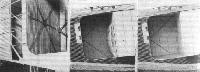
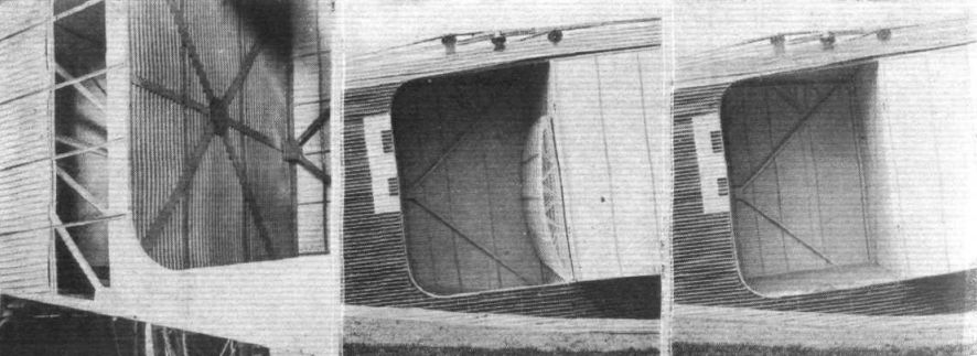
FUSELAGE DETAILS OF THE "VIASTRA I": On the left, the junction of rear to cabin portion before completely covered. In the centre view the false floor of the goods compartment is shown raised up, while on the right it is shown in place. This floor enables very heavy concentrated loads to be supported.
-
Flight 1930-09 / Flight
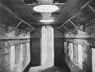
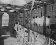
THE "VIASTRA" CABIN, LOOKING AFT: Note the roof lights. The door leads to the lavatory and exit
-
Flight 1930-09 / Flight
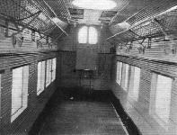
THE CABIN: The photograph shows the finished cabin, before the seats are installed
-
Flight 1930-09 / Flight
THE CABIN: The photograph shows the cabin during construction.
-
Flight 1930-09 / Flight
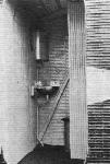
The lavatory
-

Air Enthusiast 2006-05 / A.Ord-Hume - Three? One? Two? /Airliners and air services/
Регистрационный номер: VH-UOM [3] The crash of VH-UOM pictured the following day, by which time two 50-gallon oil drums have appeared to drain off fuel.
-

Aeroplane Monthly 1989-08 / J.Stroud - Wings of Peace
Регистрационный номер: VH-UOM [3] KEITH WOODCOCK'S painting shows West Australian Airways’ second Viastra II, with uncowled engines and nose landing light.
-

Flight 1930-06 / Flight
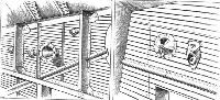
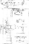
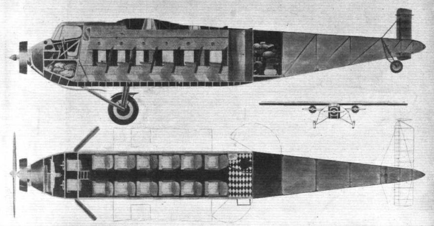
THE VICKERS "VIASTRA": These sketches give some idea of the passenger accommodation, &c. The machine will be of all-metal construction, including the covering of wing and fuselage.
-
Flight 1930-09 / Flight
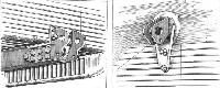
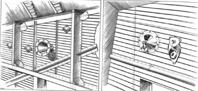
THE CABIN: The sketches show details such as ventilators, etc. Small sand bags riveted to the metal covering are intended to prevent "drumming."
-
Flight 1930-09 / Flight
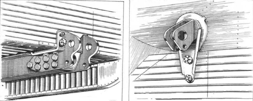
ON THE "VIASTRA": On the left the fitting to which the bent axle and main wing bracing strut are attached. On the right the fitting on the upper longeron to which is attached the diagonal strut of the wing bracing.
-

Flight 1930-09 / Flight
SOME "VIASTRA" DETAILS: On the left is shown the construction of wing spars and ribs, while on the right is a sketch of the unusual arrangement of the rudders.
-
Flight 1930-09 / Flight
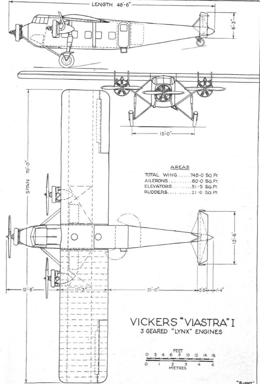
Vickers "Viastra" I 3 Geared "Lynx" Engines


- Фотографии