
Описание
Страна : США
Год : 1921
Flight, June 1922
THE BACO "SKYLARK"
PARTICULARS are to hand of yet another small, low-powered machine of American origin possessing several distinctive features. This is the BaCo "Skylark," designed and constructed by the Bethlehem Aircraft Corpn., of Bethlehem, Pennsylvania, U.S.A., a two-seater tractor biplane fitted with a 60 h.p. 3-cyl. Lawrence air-cooled engine. The pilot and passenger are seated side by side, an arrangement that has much in its favour but which is not very often adopted by designers. As may be seen from the accompanying illustrations, in general appearance this machine is not unlike the Eastchurch and Grain "Kittens" (designed by the Experimental Construction Dept. of the R.N.A.S. during the War), nearly grown up to a "Cat." It is stated that the "Skylark" possesses remarkable inherent stability, and that on releasing the "stick" the machine will settle by itself to its natural flying angle; which may be varied by the adjustable stabiliser. It will do this from either of the two extreme positions of a stall or vertical nose dive. Its lateral stability is also good. Other qualities in the "Skylark" that make it particularly suitable as a sporting or popular general-purpose machine, are its low landing-speed, quick take off - on landing it rolls but a short distance after the wheels touch the ground - the ease with which it can be handled on the ground, low operating expense, and long flight duration. The provision of an adjustable tail plane in a small machine of this description is somewhat in the nature of a novelty, if not a luxury.
The main planes are of the four-aileron type of even span and chord, with the top plane staggered forward 20 ins. They have no sweepback, but a dihedral angle of 1 1/2°; the angle of incidence of the top plane is 1 ° and that of the lower plane 0°. The comparatively thick wing section employed is U.S.A. 27. Top and bottom planes are each in two units, the bottom ones being attached to the lower longerons of the fuselage, and the top ones to a cabane of two inverted V streamline steel struts; an additional streamline strut extends forwards from the top of the cabane down to the fuselage.
Front spars are of selected spruce, 4-ply laminated rectangular sections. Rear spars are of I-beam sections of spruce. They are built up so as to form a section similar to the ordinary routed spar. It consists of two spruce members of shallow U-shape, with the bottoms of the U side by side, and with a centre piece of 1/16-in. veneer, the grain running vertically to take the longitudinal sheer.
Cap strips of the spars are of birch 1/8-in. thick. Their construction is very logical since the veneer takes the horizontal shear across the grain, and the cap strips of birch utilise a material of high strength where the fibre stress is greatest.
The internal bracing system is of double swaged wires and forked ends attached to mild steel fittings bolted to the main spars, which are left solid at these points. Main plane fittings are of standard and simple design made up of plain mild steel sheet metal. Ample strength has been allowed on all fittings, and no off-centre wire pulls are present anywhere in this machine.
The trailing edge of the wings is formed of wire, and handholes are provided on both lower wings to facilitate handling on the ground.
The wing truss is of clean design. The single I-struts which are laminated and built up of spruce are of very generous proportion.
The double lift wires, front and rear, are of stranded cable. They run forward, as well as inward, serving both as external drift wires and flying wires. The landing wires extend from the front of the cabane in the centre to the front and rear of the bottom of the interplane struts. This places the rear landing wire out of the way of entrance to the cockpit. This, together with the strut running from the centre of the plane, from the top of the cabane to the forward part of the fuselage, completes the truss for stress of every character, and at the same time reduces the parasite resistance to a minimum; nevertheless the use of the deeply-cambered U.S.A. 27 wing section enables the weight of the wing truss to be kept down to a minimum.
Wing frames are covered with approved grade A cotton fabric, and special care has been exercised in sewing the fabric to the ribs in accordance with Army specifications. Surface treatment is of six coats of Phoenix fireproof dope with a bronze finish.
The empennage is substantially built; the stabiliser is hinged on the rear end so that a large degree of adjustment is possible in flight. Since the balance of the machine is perfect for normal performance, it is expected that the stabilizer adjustment will only be used when the pilot wishes to fly at one particular flight attitude for a long period of time.
The stabiliser, as shown in one of the accompanying illustrations, has a strong rear spar running continuously over-top of the fuselage. The laminated front edge is in one piece of semi-circular shape; three ribs on either side give it adequate strength and preserve the camber required. A strong spruce member runs on either side of the fuselage from the forward point of attachment of the stabiliser toward the outer end of the rear spar. Two wires run from the top of the rudder post to the outer end of the stabiliser spar, giving added security for severe manoeuvres. The stabiliser and rudder are of similar construction, and are well braced internally. The elevator horns are skilfully disposed within the vertical fin, and a particularly strong torsion tube is provided to carry the elevator loads to the elevator horns. The design of the empennage is particularly sturdy and clean and combined with simplicity.
The fuselage is solidly constructed. A complete trussing is provided of four solid spruce longerons, with diagonal bracing members also of spruce. The whole is covered with mahogany, 3-ply veneer. Although very light, the fuselage has a strength far in excess of that required either in the air or on landing. Great care has been exercised not to weaken the fuselage at the point where the door to the cockpit is placed, special diagonal and longitudinal members being provided at that point to carry the truss through.
The smooth mahogany finish is particularly pleasing to the eye and touch. A veneer fuselage of this type eliminates all fittings and provides a good production job easy of repair. The combination of veneer with the complete wooden truss also eliminates all tendency for warping or distortion of veneer.
In the cockpit ample room is provided for two persons side by side, together with dual control. The instruments are symmetrically arranged on a dashboard clearly seen by either occupant. The engine controls - namely, switch, altitude adjustment and spark - are placed on the right-hand side. The throttle is placed between the occupants and easily accessible to both. The instrument board carries a banking indicator, turn indicator, air speed meter, altimeter, tachometer, oil pressure gauge, oil temperature gauge and air distance recorder. A compass completes the equipment.
The arrangement of the cockpit and instruments is such as to make a perfect dual control arrangement, but with more facility for engine control, thus giving to the pilot a valuable point in instruction flying.
The machine is easily entered by means of a low step on to the wing, and another low step into the cockpit through the side-door entrance in the body. The control stick and rudder bars are of the standard type. The roomy upholstered cockpit, with attractive instrument board, presents a pleasing and comfortable compartment for the pilot and passenger. To carry a few hundred pounds of mail, express or baggage, instead of a passenger, the extra seat is pushed back, or removed, and the control stick is removed also, giving ample cargo space.
The chassis is of 5/8-in. by 1 1/2-in. oval steel tubing brazed to a guide plate, which allows a 4-in. travel of the axle. The shock absorber cord is simply wound about two spools, provided on the axle, and down under the guide plates. The cross wiring for the chassis struts is provided on both the front and rear struts. Two compression tubes run between the lower end of the front and rear struts. The chassis is very simple in construction, and can be dismounted and assembled in a few minutes.
The 60 h.p. Lawrence engine efficiently blends into the nicely streamlined body, only the cylinders being exposed. It is supported by two steel plates, one on either side. These plates are bolted to the vertical veneer nose panel, which in turn is braced by two veneer tie-panels to the longerons. This eliminates all cross bracing wires in the first two sections, giving a very strong mounting. Two complete double ignition systems are provided with double batteries, so that either battery can be used on either system. Ample space is provided around the dual ignition system and oil leads to the engine. A fireproof wall separates the engine and ignition system from the petrol tank and cockpit, thus eliminating, as far as possible, risk of fire - the carburettor hanging outside and underneath the engine.
The principal characteristics of the “Skylark" are as follows :-
Span 29 ft. 10 ins.
Chord 4 ft.
Gap 5 ft.
Stagger 1 ft. 8 ins.
Overall length 23 ft.
Overall height 8 ins.
Wing curve U.S.A. 27
Dihedral angle 1 1/2°
Area of main planes 214 sq. ft.
Weight empty 700 lbs.
Useful load 600 lbs.
Loading/sq. ft. 5 lbs.
Loading/h.p. 19.3 lbs.
Speed range 33-9° m.p.h.
Climb (full load) 600 ft./min.
Ceiling 18,000 ft.
Duration 4 1/2 hrs.
Petrol tank capacity 20 gals.
Oil tank capacity 2 gals.
- Flight, June 1922
THE BACO "SKYLARK"
Фотографии
-

Flight 1922-06 / Flight
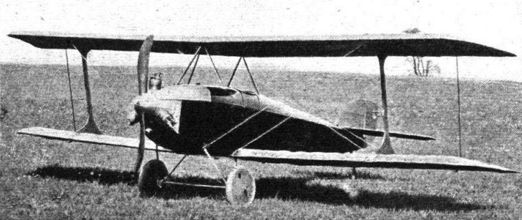
The BaCo "SKYLARK": Three-quarter front view.
-

Flight 1922-06 / Flight
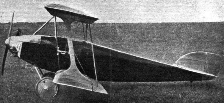
The BaCo "SKYLARK": Side view.
-

Flight 1922-06 / Flight
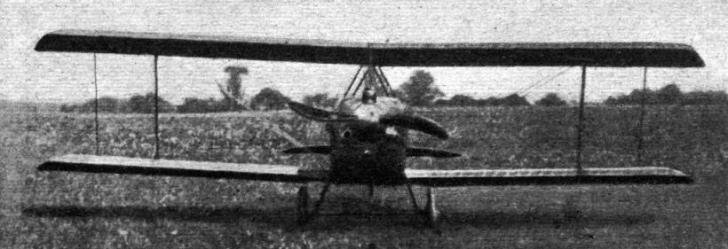
THE BaCo "SKYLARK": Front view.
-

Flight 1922-06 / Flight
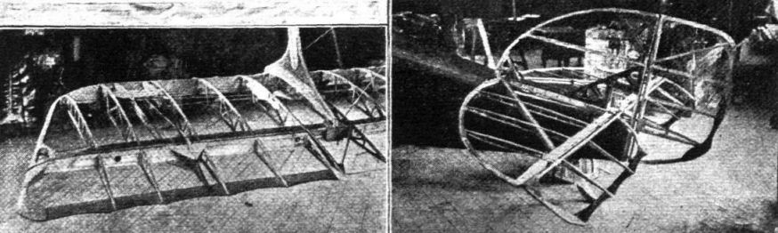
THE BaCo "SKYLARK": Two views showing, on the left, a portion of the lower wing uncovered, and, on the right, the tail planes, also uncovered.
- Фотографии