
 Wiki
Wiki 
Варианты
- ANEC - I / II - 1923 - Великобритания
- Beardmore - W.B.XXIV Wee Bee - 1924 - Великобритания
Flight, March 1923
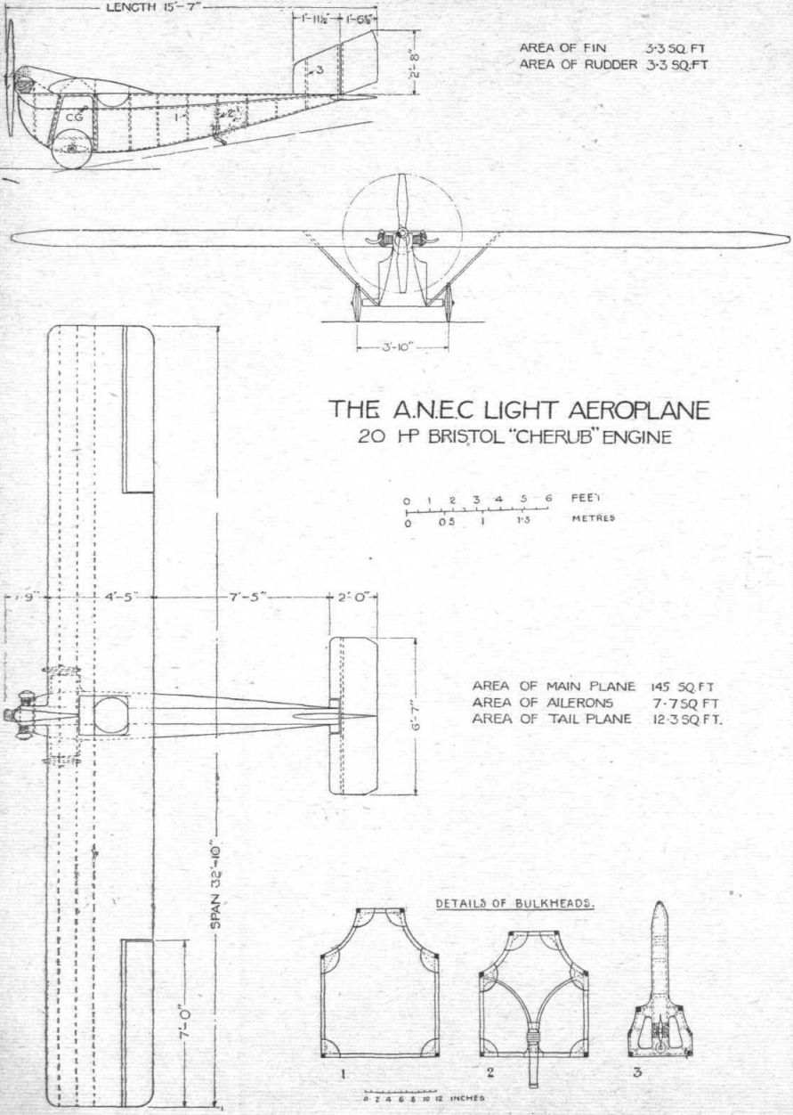
THE A.N.E.C. LIGHT AEROPLANE
20 H.P. Bristol "Cherub" Engine
IN describing the Bristol "Cherub" engine (March 1, 1923) we stated that this low-powered engine promised really to "fill a long-felt want." We did not then anticipate the prompt attention which the engine would attract, and, consequently, it is the more gratifying to be able to record that the Air Navigation and Engineering Company, of Addlestone, Surrey, of which Mr. N Chereau is managing director, has got out the complete designs for a small machine to take this engine. The designs are due to Mr. Shackleton, and, as the accompanying general arrangement drawings will show, the new little machine, which, for want of a better term we, describe as a “light aeroplane" (following motor-car practice of speaking of a light car), is of very pleasing lines indeed, and with its small overall size, and particularly low height (less than 4 ft.) could scarcely fail to appeal to anyone interested in aircraft.
We have had the privilege of going through the performance figures with Mr. Shackleton, and we are frankly astonished at the excellence of the aerodynamic design. Mr. Shackleton has evolved for this machine a special wing section, which in model form and not tested at a particularly high velocity, gave a maximum L/D of 22, while the maximum lift coefficient was somewhat above 0-65. By reducing external bracing and all extraneous parts to a minimum Mr. Shackleton has been able to bring the maximum L/D of the whole machine up to the very good figure of 16-5. The consequence is that, as the machine is light and lightly loaded very small power is required for horizontal flight, and the ceiling is correspondingly high. We mention this, not because a high ceiling is of any particular value in a machine of this type, but because the characteristics which give a high ceiling are the characteristics that are desired for other reasons in such a machine. It should not be assumed that because the ceiling is high the machine has a rapid climb. (As a matter of fact, the climb is sufficiently good, but not nearly so astonishing as the ceiling. The estimated climb to 3,000 ft. is eight minutes.) This will be appreciated when it is remembered that rate of climb is mainly a matter of light loading per horsepower, while high ceiling is chiefly attained by having a good excess of horse-power available over horse-power required, even if the power loading is somewhat high. Thus, in the case of this machine., the power loading (on 20 h.p.) is 22-9 lbs./h.p., which is a reasonably high figure, and yet the high ceiling is attained. The machine would probably take something like three hours to reach the ceiling.
In external appearance the A.N.E.C. light aeroplane might, perhaps, be described as a Dornier built on a very much reduced scale. The high engine position, the parallel semi-cantilever wing, the short cantilever beams projecting from the floor of the fuselage and carrying the shock absorbers, and the general appearance are suggestive of the Dornier "Komet." We are not in any way accusing Mr. Shackleton of copying Dornier. It merely so happens that in combining the features which he has thought desirable he has arrived at much the same arrangement. Constructionally this small machine is, of course, entirely different.
The new A.N.E.C. monoplane incorporates in its construction several novel features, most important of which is, perhaps, the wing spar construction. In the past it has been customary to have two spars, placed a considerable distance apart. In the German gliders the single spar construction, strengthened by covering the entire leading edge with plywood, has gained much favour recently, as providing good resistance to torsion. Mr. Shackleton has, in a way, combined the two systems, with a touch of Junkers multi-spar construction, in the new monoplane, and as this form of spar is, of course, applicable to other machines as well, its construction will be dealt with at some length.
Fundamentally the spar consists of three stringers, running across from wing tip to wing tip, and covered by three-ply wood. The apex of the triangle thus formed is at the top of the wing section, and the base at the lower surface. It might be objected that a better plan would have been to reverse the position, standing the triangle on its apex, and thus have got more material on the top of the spar, where, as regards the cantilever portion, the top is in compression. While this would be so the advantage would have been smaller than might be expected at first glance owing to the configuration of the usual wing section, i.e., approximately flat bottom and deeply cambered top surface. This would reduce the overall depth of the spar, and there might be little or no gain. On the other hand, the present arrangement has several practical advantages. Thus the flat bottom of the spar forms a very convenient base for attachment to the fuselage. With the pilot placed where he is, the slope of the rear spar wall materially improves the view in a forward and upward direction. Finally, the spar forms, with the three-ply covered leading edge, a member that is particularly good in torsion. It might be added that breaking tests have shown the moment of resistance to be such that the spar successfully withstands bending loads which impose a maximum fibre stress of 6,200 lbs./sq. in. In torsional tests the spar withstood a torque resulting in torsional shear stress of 800 lbs./sq. in. In both cases the moment of resistance was calculated on the total area of the cross section of the spar.
As regards details, the three corner strips of the spar are of spruce, and are tapered towards the tip in such a way that, while the overall size of the spar remains the same, the corner strips taper considerably. The same applies to a certain extent to the ply-wood covering, which is about 5/32 inch thick at the point of maximum bending moment, and only 1 mm. thick at the tips. The ply-wood is, of course, put on in panels, successive ones of which become thinner as the tips are approached. The ply-wood panels are attached to the corner strip by glueing and tacking.
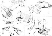
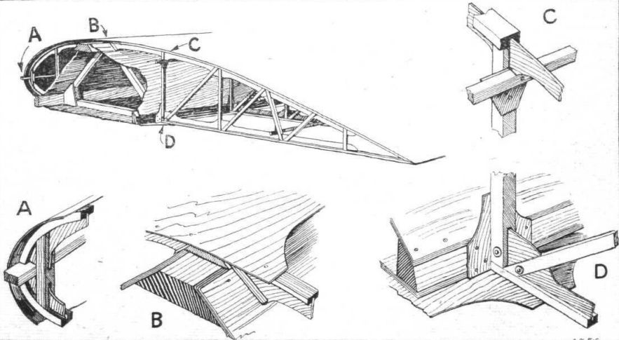
The ribs are built up of grooved flanges of spruce, into which are let narrow strips of thin three-ply, the shape being maintained by distance pieces, having saw-cuts in their ends where these fork over the ply-wood web strips. The arrangement is shown in one of our sketches.
This form of spar construction would appear to be particularly applicable to metal construction, and we hope that the wider scope offered in this direction will be made full use of. We might add that the triangular spar construction has been patented by the Air Navigation and Engineering Company.
The fuselage is composed of a light framework covered with thin three-ply wood. The bulkheads are, in most cases, skeletons with gussets of three-ply wood where two or more members meet. Where local considerations demand, the bulkheads are of more solid construction, with internal struts and a covering of ply-wood front and back, thus forming a box. This is the case where the wing tubes attach and in similar places. At the rear of the fuselage these bulkheads are built up to form the vertical fin, which is thus virtually integral with the fuselage.
The pilot is placed in a low hammock seat, and a hole in the middle of the wing serves as a means of entering and leaving the cockpit, as well as for giving a better view. Reference has already been made to the fact that the sloping rear surface of the wing spar improves the view in a direction obliquely upwards and forwards. The "hollow-ground" deck of the fuselage facilitates looking directly forward of the machine, and altogether the view is probably as good as it is humanly possible to make it in a tractor machine.
The undercarriage, as already indicated, consists of two wheels mounted on the usual tubular axle, but the rubber cord shock-absorbers of which are supported from the free ends of two tubular cantilever beams projecting laterally from the floor of the fuselage. On their ends these beams carry fish-plates having slots for the axle to work in, as shown in our drawings. The whole will be enclosed in a streamline fairing.
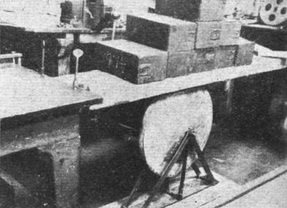
The wheels call for a somewhat detailed description, as they are of very unorthodox design. Mr. Shackleton frankly admits that they are not his own invention, as wheels of this type have been made and tested in Germany. He has, however, improved on the construction, and has produced a wheel which, for a weight of 5 lbs., will support a tremendous load. On the day of our visit to the Addlestone works one of these wheels was being tested, and the accompanying photograph, showing the wheel under test, was secured by our photographer on this occasion. The load sustained when the photograph was taken was considerably over 1,000 lbs., and it is thought that the wheel will carry probably nearly twice that load before collapsing. As the 1,000 lbs. give a factor of safety of 4, there is little need to worry about greater strength.
Constructionally the wheel is made of a rim of ash strip, wound around a mould spirally, the ends being tapered down and.the wheel turned later to make it perfectly true. Five "spokes" support the rim, and are secured to the rim and the hardwood hub by triangular fillets. The whole is then covered with ply-wood. A short phosphor-bronze bush is inserted in the hub at each end, and a leather strip is put around the rim to form a "tyre," and the wheel is finished. In view of the low weight, great strength, and cheapness of production, this form of wheel deserves to be more generally used on very light machines.
The controls are of more or less orthodox type, with the exception of the aileron controls. A short crank-arm projects laterally from the longitudinal rocking shaft, and from it a tube rubs to an L crank inside the wing. From the other arm of this L crank cables run to the aileron king posts via large pulleys. The ailerons are of usual type, except that they are carried on a false spar, and are hinged at the lower corner instead of in the centre of the section.
The wing is built in one piece, and is attached to the fuselage by sheet-steel stirrup strips passing over the triangular spar. Externally the wing is braced by two struts on each side. These struts, which are of tubular section, are attached to stirrup strips passing over the spar, and are prevented from sliding along the latter by a triangular block of wood, beveled to accommodate the slope of the straps.
As already stated, the engine is a Bristol "Cherub" of 20 h.p., mounted high in the nose of the fuselage, and driving, through a two-to-one reduction gear, a two-bladed tractor airscrew. The high engine position (which is not objectionable in such a small machine, owing to the relatively unimportant forces set up) has allowed of getting ample clearance for the propeller, while at the same time keeping the machine very low on the ground. In fact the pilot could, without difficulty, step straight from the ground into the cockpit.
Owing to the high position of the engine, and the fact that in the Bristol "Cherub" the carburettor is placed above the engine, it has not been possible to provide gravity feed. This seems a great pity, as gravity feed is almost essential in a simple, cheap machine.
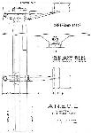
The main characteristics of the A.N.E.C. light aeroplane are as follows: Length overall, 15 ft. 7 ins. Wing span, 32 ft. 10 ins. Overall height (with propeller horizontal), about 4 ft. Weight of machine empty, 273 lbs. (composed as follows: Engine and propeller boss, 86 lbs.; propeller, 10 lbs.; wing and struts, 90 lbs.; fuselage, 40 lbs.; tail unit, 12 lbs.; undercarriage, 17 lbs.; controls and instruments, 12 lbs.; tanks and connections, 6 lbs). Weight of fuel, 30 lbs. Pilot, 155 lbs. Total loaded weight, 458 lbs. Wing loading, 3-15 lbs./sq. ft. Power loading, 22-9 lbs./h.p. Maximum speed, 78 m.p.h. Cruising speed, 66 m.p.h. Landing speed, 32 m.p.h. Fuel consumption, one gallon per 60 miles. Climb to 3,000 ft. in eight minutes; to 12,000 ft. in 52 minutes. Ceiling, 25,000 ft.
The estimated maximum speed is somewhat high, but Mr. Shackleton informs us that this occurs at an angle of incidence of -4 degrees. In consequence the machine would probably be somewhat unpleasant to fly, and pilots would not be tempted to be flying always "all-out." That, we think, is a good feature, and should result in better engine reliability and increased economy. Another feature of the machine which should make for safety is that the wing section used, although being of fairly deep top camber, does not show a sudden break in the lift curve at stalling angle, the curve dropping very gradually. Thus it should be difficult for a somewhat inexperienced pilot to stall the machine violently and thus getting into a spin or nose dive. The factor of safety is high throughout, and stress calculations indicate that it should be practically impossible for a pilot to break any part in the air. Thus, even if the wing struts on one side should break (a very unlikely contingency), the wing structure should, according to the stress calculations, still be strong enough to hold together and thus enable the pilot to make a landing.
With a landing speed of about 30 m.p.h. and a wing loading of only just over 3 lbs./sq. ft. it should be possible to put the machine down in almost any small field, especially as the tail skid is mounted some distance forward of the tail, and thus should act as a fairly effective brake and pull the machine up quickly.
For sporting purposes there can be no doubt that a machine of this type should have a very wide appeal, and we hope that more than one will take part in the point-to-point race for the Grosvenor Cup on June 23. The possibilities of the type do not, however, finish here by any means. For instance, it is not difficult to imagine a number of such machines being used for training purposes, forming a stepping-stone between the glider and the larger power-driven machine. Thus, one can visualise a system of training whereby the pupil starts on a glider, proceeds to a light aeroplane, then to a fairly low-power machine of more orthodox type, and finally to the fast fighter and scout. Another field of utility would be their use as messenger 'planes for the R.A.F. There is very frequently a necessity for sending communications from one station to another, and instead of using an expensive machine burning a lot of petrol, these small machines could very well be used, the cost being negligible. A few might be stationed at Croydon, Stag Lane, etc., for use by Air Ministry officials when visiting various stations.
In the Colonies the type should be particularly useful as runabouts. There must be thousands who live far from towns, such as ranch owners, etc., who would be glad to use such a small, cheap machine.
Altogether, we think Mr. Shackleton and the Air Navigation and Engineering Company (which, we are glad to learn, is now entirely under British control) are to be congratulated on a very promising and clever design, and we shall hope to see large numbers of these machines take a prominent part in sporting aviation during the next few years.
Описание:
- Flight, March 1923
THE A.N.E.C. LIGHT AEROPLANE - Flight, September 1924
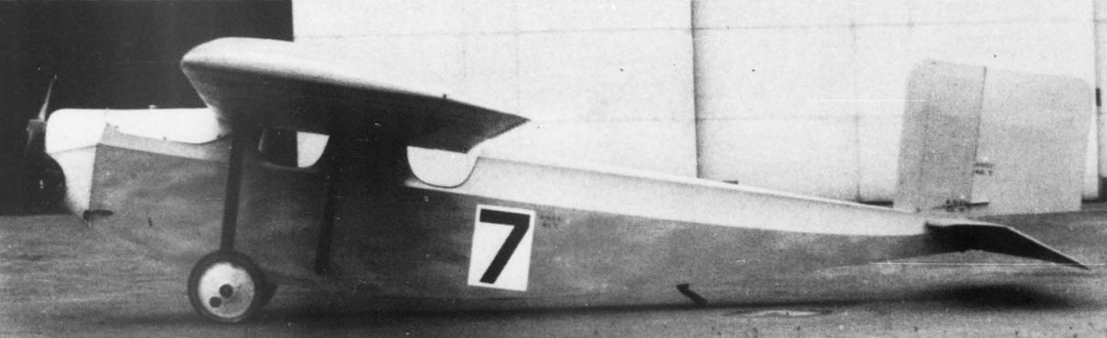
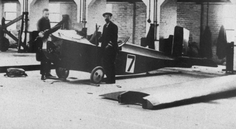
THE "A.N.E.C. II" LIGHT MONOPLANE (No. 7)
Фотографии

-
Aeroplane Monthly 2001-11 / News
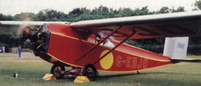
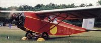
Регистрационный номер: G-EBJO [8] Chris Morris runs-up the ABC Scorpion engine in ANEC II G-EBJO on July 6, 2001.
-

Aeroplane Monthly 1984-09 / R.Riding - ANEC I /British pre-war ultralights/ (42)
The A.N.E.C. (700 c.c. Blackburne vee twin, inverted)
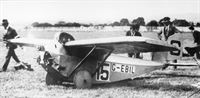
ANEC I G-EBIL being wheeled out at Lympne in October 1923. -
Flight 1926-09 / Flight
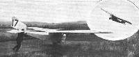
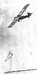
A 1923 WINNER: The A.N.E.C. with Blackburne Engine which tied with the "Wren" for first prize. 87-5 miles per gallon. James wheeling his machine out before a flight, and, inset, a typically banked turn.
-
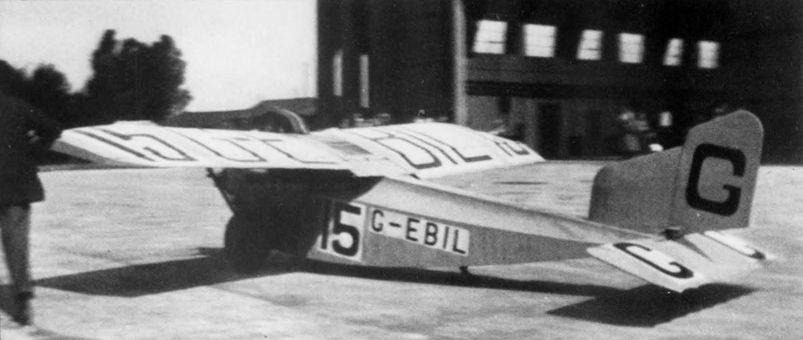
Aeroplane Monthly 1984-09 / R.Riding - ANEC I /British pre-war ultralights/ (42)
Регистрационный номер: G-EBIL [3] The clipped icing ANEC IA G-EBIL at Lympne during the August Bank holiday of 1925 where Jimmy James took the speed prize with an average speed of 83 7 m.p.h. over a 50km course.
-
Aeroplane Monthly 1984-09 / R.Riding - ANEC I /British pre-war ultralights/ (42)
Регистрационный номер: G-EBIL [3] The clipped wing ANEC IA competing at the Royal Aero Club Lympne races during the August Bank holiday in 1925. It is powered by a 1,100 c.c Anzani engine.
-
Aeroplane Monthly 1974-01 / B.Martin - Britain's civil aircraft register
Регистрационный номер: G-EBIL [3] Mr. Reynolds gets down to it: Starting "Jimmy'' James in the A.N.E.C. is a somewhat difficult business.
The A.N.E.C.I., G-EBIL, was designed by W. S. Shackleton and was one of Britain's first ultra-light aircraft. It was entered in the 1925 Lympne Trials, and in the hands of J. H. James reached a height of 14,000ft after earlier flying 87-5 miles on a single gallon of petrol, powered with the 698cc Blackburne Tomtit. -

Flight 1930-01 / Flight
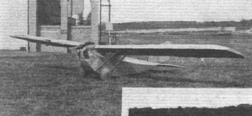
The light 'plane of to-day may be said to have been evolved from machines of much lower power. Shown is one of single-seaters from the Lympne competition: the A.N.E.C.
-
Flight 1923-08 / Flight
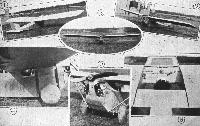
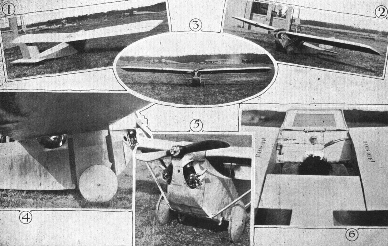
THE A.N.E.C. LIGHT 'PLANE, 700 c.c. BLACKBURNE ENGINE: 1, Three-quarter rear view. 2, Three-quarter front view. 3, Front view showing dihedral. 4, View under the wing, showing clear field of vision obtained. 5, The engine mounting and undercarriage. The engine is inverted. The wheels are entirely of wood, and weigh but 4 lbs. 2 oz. each. 6, Looking into the cockpit from above. The triangular section spar contains the petrol tank. A transparent cover is placed over the cockpit when the machine is flying.
-
Aeroplane Monthly 1984-09 / R.Riding - ANEC I /British pre-war ultralights/ (42)
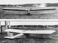
The two photographs were taken at Brooklands in August 1923. They show the unmarked prototype ANEC I at the time of its first flight, after addition of the larger rudder.
-

Aeroplane Monthly 1984-09 / R.Riding - ANEC I /British pre-war ultralights/ (42)
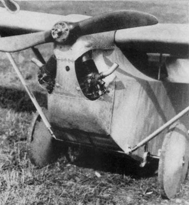
Close-up of the first ANEC I showing the neatly cowled Blackburne Tomtit engine installation.
-

Aeroplane Monthly 1984-09 / R.Riding - ANEC I /British pre-war ultralights/ (42)
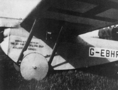
Регистрационный номер: G-EBHR [2] Close-up of the cockpit area of ANEC I G-EBHR showing the pilot's restricted view.
-
Flight 1923-10 / Flight
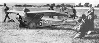
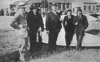
Members of the A.N.E.C. contingent at Lympne: From left to right, Mr. and Mrs. Shackleton, Dr. Hope, Mr. James, and Mr. Piercey. "The Doctor" has taken a week's holiday, and is spending it at Lympne, where he has volunteered his services, should they be required.
-
Flight 1923-11 / Flight
LIGHT 'PLANES AT HENDON: 1. James on the Addlestone A.N.E.C. monoplane (Blackburne engine).
-
Flight 1923-11 / Flight
Регистрационный номер: G-EBHR [2] LIGHT 'PLANES AT HENDON: 2. Piercey on Hubert Blundell's A.N.E.C. monoplane (Blackburne engine).
-
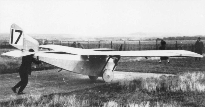
Flight 1924-09 / Flight
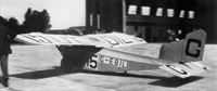
ONE OF TWO PRIZE-WINNERS AT LYMPNE: James's A.N.E.C. monoplane (No. 17), on which he tied with Flight-Lieut. Longton, flying the "Wren" No. 4, for the Duke of Sutherland's and the "Daily Mail" prizes.
-
Flight 1923-10 / Flight
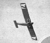
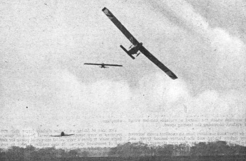
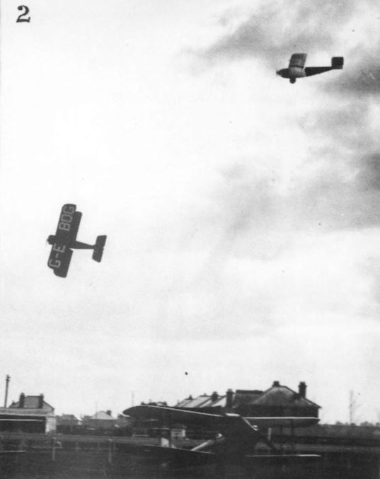
Capt. Cockerell on the Vickers "Viget" (No. 10) flying above one of the A.N.E.C. monoplanes (No. 17) at Lympne.
Другие самолёты на фотографии: Vickers Viget - Великобритания - 1923
-

Flight 1923-11 / Flight
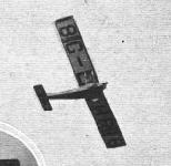
LIGHT 'PLANES AT HENDON: "Jimmy" James banking - and leading - in the third heat of the Handicap Race. Close behind are F.P.Raynham (left) on the Handasyde and (right) Capt. Macmillan on Parnall "Pixie II."
Другие самолёты на фотографии: Handasyde monoplane - Великобритания - 1923Parnall Pixie - Великобритания - 1923
-
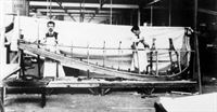
Aeroplane Monthly 1984-09 / R.Riding - ANEC I /British pre-war ultralights/ (42)
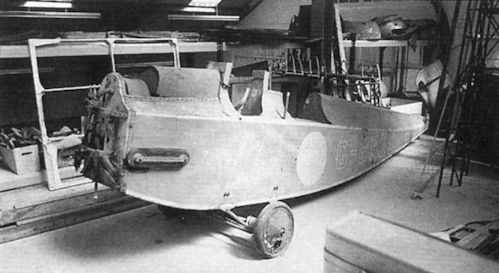
One of the ANEC Is under construction at Addlestone in 1923.
-

Flight 1923-03 / Flight
The all-wood wheel of the A.N.E.C. Light Aeroplane under test. The load supported when this photograph was taken was over 1,000 lbs., and the wheel showed no sign of breaking. The weight of the wheel is 5 lbs.


-

Aeroplane Monthly 1985-06 / R.Riding - ANEC II /British pre-war ultralights/ (51)
THE "A.N.E.C. II" MONOPLANE: Three-quarter rear view.
-

Aeroplane Monthly 1985-06 / R.Riding - ANEC II /British pre-war ultralights/ (51)
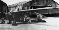
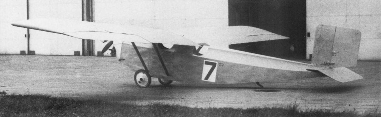
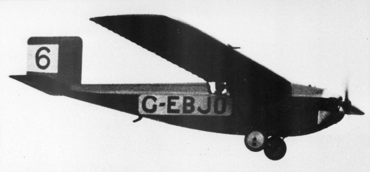
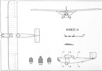
View of the ANEC II in its original configuration, with two-cylinder Anzani engine and simple bent-tube undercarriage. The ANEC II was numbered 7 for the Lympne trials.
-
Flight 1924-09 / Flight
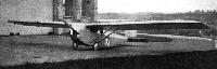
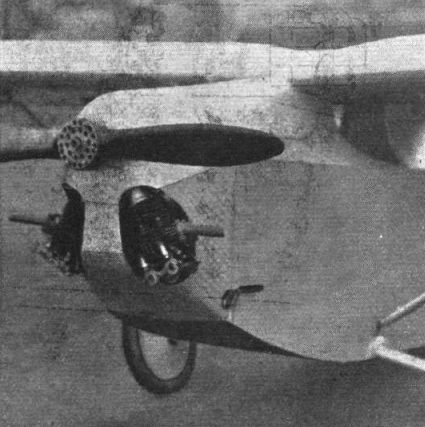
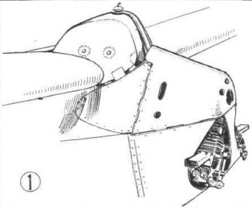
THE "A.N.E.C. II" LIGHT MONOPLANE: This three-quarter front view gives a good idea of the lines of the machine, which are exceptionally "clean." Note the inverted position of the 1,100-c.c. Anzani engine, and the manner in which this mounting improves the view. Gravity feed from the tank in the deck fairing is also facilitated.
-

Aeroplane Monthly 1985-06 / R.Riding - ANEC II /British pre-war ultralights/ (51)
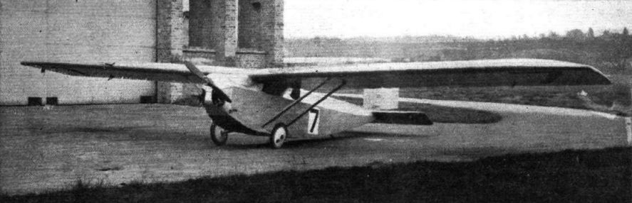
The ANEC II at Lympne, September 1923.
-

Flight 1924-09 / Flight
The Anzani engine in the "A.N.E.C. II" monoplane. Note the inverted position.
-
Flight 1924-10 / Flight
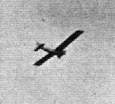
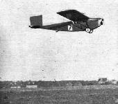
AT LYMPNE: The A.N.E.C. II monoplane well away on a test flight.
-

Aeroplane Monthly 1985-06 / R.Riding - ANEC II /British pre-war ultralights/ (51)
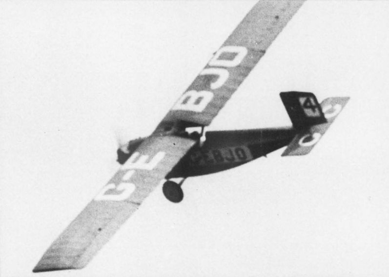
Регистрационный номер: G-EBJO [8] Norman Jones flying the ANEC II during the 1927 King’s Cup air race held on August Bank Holiday. He was the first to take off but retired at Skegness after hitting a bird.
-
Flight 1927-07 / Flight
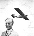
Регистрационный номер: G-EBJO [8] THE BIRMINGHAM AIR PAGEANT: The winner of the Air League Challenge Cup, Mr. Norman Jones, and his A.N.E.C. II monoplane (Bristol "Cherub II").
-

Aeroplane Monthly 1985-06 / R.Riding - ANEC II /British pre-war ultralights/ (51)
Регистрационный номер: G-EBJO [8] Norman Jones racing the ANEC II at Bournemouth in June 1927.
-
Flight 1927-06 / Flight
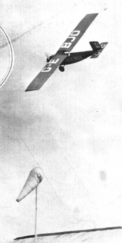
Регистрационный номер: G-EBJO [8] THE PRIVATE OWNERS' HANDICAP: Jones cornering on the ANEC II.
-

Aeroplane Monthly 1981-09 / A.Wheeler - The Bournemouth Easter Meeting
Регистрационный номер: G-EBJO [8] GOOD FRIDAY AT BOURNEMOUTH: 2, Dudley Watt on his S.E.5A cuts under Jones on the ANEC II while rounding the turning point.
Другие самолёты на фотографии: RAF S.E.5 - Великобритания - 1916
-
Aeroplane Monthly 1985-06 / R.Riding - ANEC II /British pre-war ultralights/ (51)
Регистрационный номер: G-EBJO [8] The ANEC II seen with later-type strutted undercarriage. The engine cowlings have been removed to reveal the Anzani engine.
-

Aeroplane Monthly 1989-10 / M.Oakey - Grapevine
Регистрационный номер: G-EBJO [8] A glimpse inside the Shuttleworth Collection’s newly-established store at Old Warden: ANEC II G-EBJO awaits the attention of the restorer.


-
Flight 1923-03 / Flight
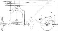
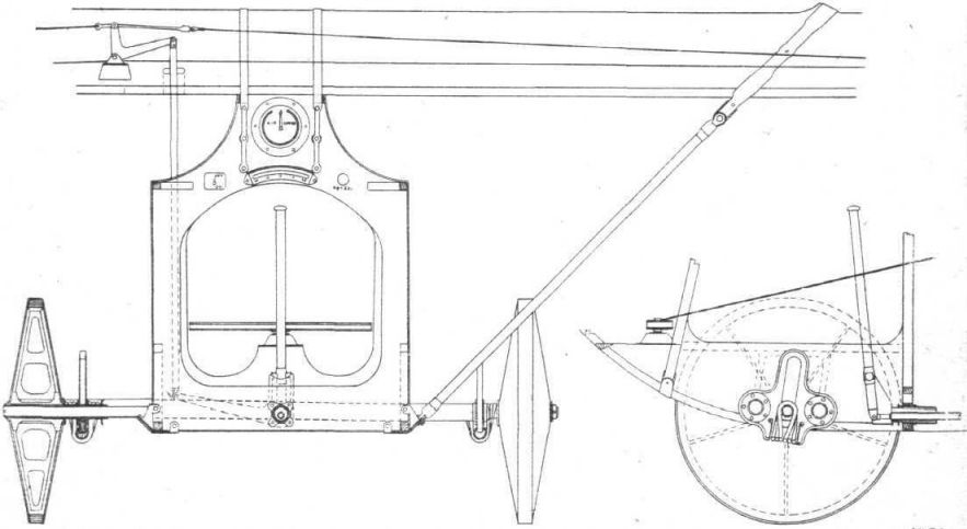
THE A.N.E.C. LIGHT AEROPLANE: Part-section through fuselage in way of pilot's seat, looking forward. Note the aileron control and the cantilever undercarriage.
-
Flight 1923-03 / Flight
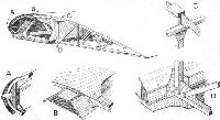
THE A.N.E.C. LIGHT AEROPLANE: Some constructional details of the wing. The spar is of triangular section, and is built up of three corner strips of spruce, joined under each rib by an internal triangle formed of thin spruce strips. The whole is covered with ply-wood. The entire leading edge is covered with ply-wood.
-

Flight 1925-08 / Flight
A FEW DETAILS AT LYMPNE: 1. The enlarged petrol gravity tank on the A.N.E.C. monoplane.
-
Flight 1925-08 / Flight
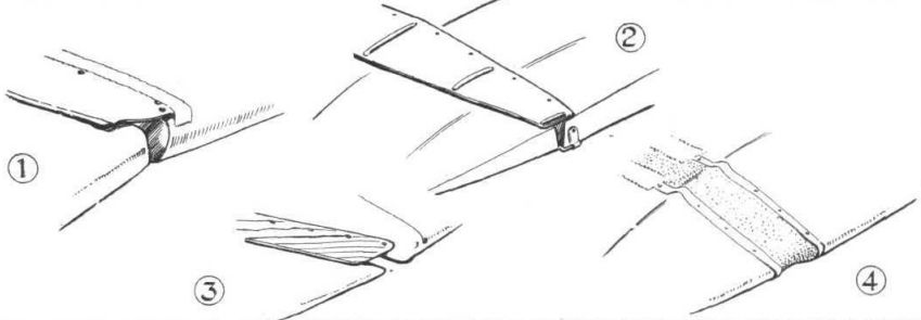
"STOP THAT LEAK": Different methods of closing the gap between rear spar and aileron in some of the Lympne machines. 1. In the Beardmore "Wee Bee" an aluminium strip is used with edges turned over for stiffening purposes. The front edge is covered by fabric strip doped on. 2. In the A.N.E.C, an aluminum strip is used, stiffened by fore-and-aft corrugations, while in 3, the Parnall "Pixie II" three-ply is employed, and in 4, the Cranwell monoplane, rubber strip. This was later removed as it tended to cause the controls to work stiffly.
Другие самолёты на фотографии: Beardmore W.B.XXIV Wee Bee - Великобритания - 1924Comper Cranwell III / CLA.3 - Великобритания - 1925Parnall Pixie - Великобритания - 1923
-
Flight 1924-09 / Flight
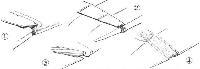
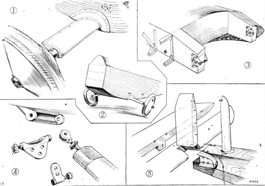
SOME CONSTRUCTIONAL DETAILS OF THE A.N.E.C. MONOPLANE: 1, A general view of one side of the very simple undercarriage. The axle is a bent tube, so fixed in the sides of the fuselage that it cannot turn. The only springing is that provided by the flexibility of the axle, and by the pneumatic tyres. The view in Fig. 2 gives an idea of the general arrangement of the chassis. 3 shows the root of the port wing with cut-out portion for front cockpit. The wing spars are hinged to the top fairing of the fuselage. 4, Details of the lift-strut attachment to the wing spar. The lower end of the strut is secured to the fitting shown in 1. The tail, Fig. 5, is attached to the stern of the fuselage as shown, the fin being in two sections of which one is integral with the fuselage structure. The elevator carries out the lines of the fuselage, and is hinged at its upper edge, being operated by a push-and-pull rod from the body.
-

-
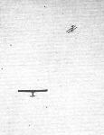
Flight 1923-03 / Flight
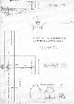
The A.N.E.C. Light Aeroplane 20 hp Bristol "Cherub" Engine
-
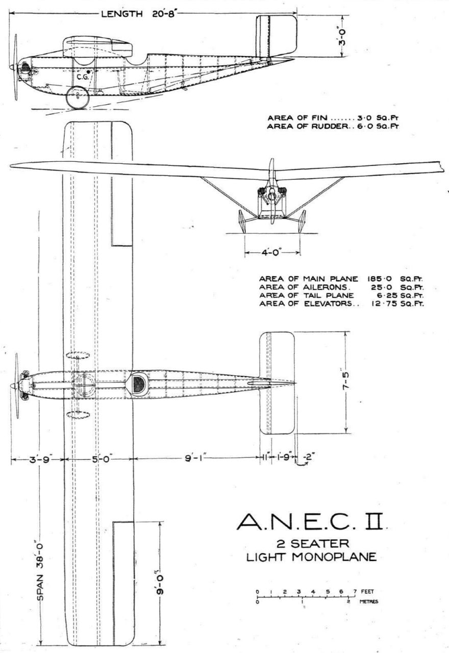
Flight 1924-09 / Flight
A.N.E.C. 2-seater Light Monoplane
-

- Фотографии