
 Wiki
Wiki 
Flight, July 1924
THE SHORT "LIGHT 'PLANE TWO-SEATER
Bristol "Cherub" Engine
GRADUALLY the machines being built for this year's light 'plane competitions at Lympne are beginning to take form. We believe that three or four are almost finished, and are only waiting for engines, while others are in various stages of progress, ranging from those designed but the construction of which has not been begun, to those nearing completion. By the courtesy of Short Brothers of Rochester, we are able to lay before our readers this week the first illustrated description to be published of the Short monoplane two-seater, which this firm has designed and is constructing at their Rochester works.
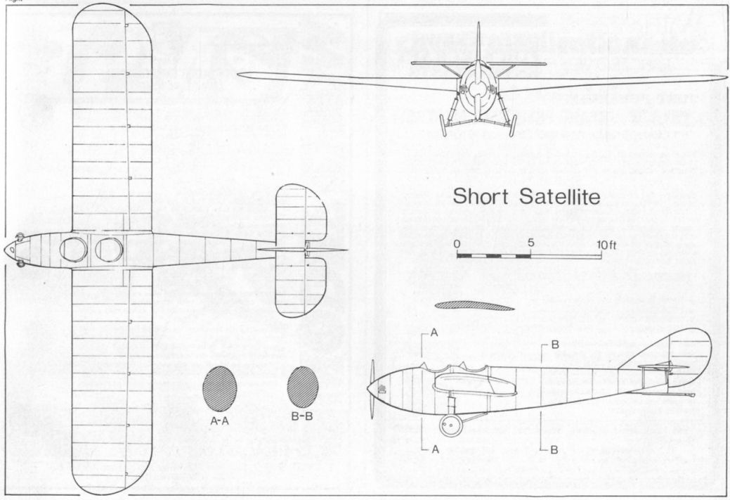
The Short light 'plane two-seater is an ordinary monoplane, if by "ordinary" one understands a monoplane in which the wing is neither of the "parasol" nor of the "low" type. Apart from the fact that the machine is a cantilever monoplane, i.e., without external wing bracing, the Short machine is of interest on account of the fact that the fuselage is built entirely of Duralumin, following the same method that has been successfully employed in the Short "Silver Streak," "Springbok," and, more recently, in the little twin-engined light flying boat described and illustrated in FLIGHT on April 17, 1924. By this form of construction, originated by Mr. Oswald Short, the outer covering, which is of Duralumin sheet, is riveted to circular or elliptical rings of L-section which form the "frames" of the structure, the outer covering or planking resisting the stresses, assisted by longitudinal stiffening strips, which do not, however, run through from end to end, but are interrupted at the frames. In the two-seater light 'plane the fuselage is of elliptical cross-section, and should have a very low head resistance, as the shape is particularly smooth.
The wings of the first machine have spar flanges of laminated mahogany, with three-ply walls, but later machines of this type will probably have spars built up of high-tensile steel strip, thus making it entirely metallic, with the exception of the fabric wing covering. The ribs are also of Duralumin, in the form of sections built up to form a "Warren girder." The two halves of the monoplane wing are bolted to strong fuselage frames by fish-plates and large-diameter hinge pins so as to facilitate dismantling. The wing section employed is a high-speed section over the outer half of the wing, gradually changing into a deep section at the root, where the maximum stresses occur. The ailerons extend the whole length of the wings, and are operated by torsion tubes and rods. A variable camber device is fitted which enables both ailerons to be pulled down together, while still retaining their differential aileron action. The controls for varying the camber, as well as the usual aeroplane and engine controls, are in duplicate, so that the machine may be piloted from either cockpit.
The undercarriage is of simple V-type, with shock-absorbers in the form of rubber blocks in compression, incorporated in the front "legs." The wheels are standard "Palmer" type, measuring 450 mm. by 60 mm.
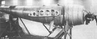
The Bristol "Cherub" engine is mounted in the nose of the fuselage, on an aluminium alloy casting, and the whole cowled-in to give a clean entry for the air. The small-diameter propeller is fitted with a spinner. Behind the engine there is a fire-proof bulkhead, aft of which are mounted the petrol and oil tanks. Fuel supply is by gravity feed. The capacity of the petrol tank is approximately 3 1/2 gallons.
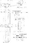
Later on we hope to have an opportunity of publishing a more detailed description of this interesting machine, illustrated by sketches and photographs. In the meantime the following brief specification may be of interest: Length, o.a., 23 ft. 9 ins.; wing span, 34 ft.; chord, 5 ft. 6 ins.; wing area, 168 sq. ft.; weight of machine empty, 483 lbs.; useful load, 367 lbs.; total loaded weight, 850 lbs.; wing loading, 5.05 lbs./sq. ft.; power loading, 30-4 lbs./b.h.p. The estimated top speed is 73 m.p.h. and the stalling speed 37 m.p.h. It would appear that both are very conservative estimates.
Описание:
- Flight, July 1924
THE SHORT "LIGHT 'PLANE TWO-SEATER - Flight, September 1924
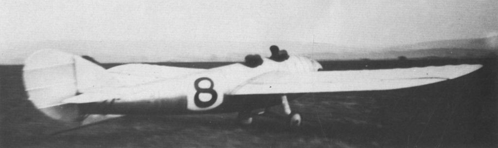
THE SHORT LIGHT MONOPLANE (No. 8) - Flight, September 1926
British Light ‘Plane Development & Lympne Meeting
Фотографии

-
Flight 1924-09 / Flight
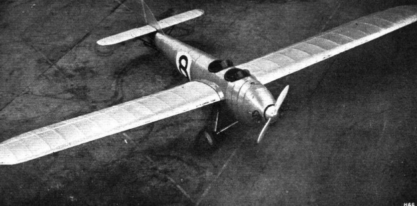
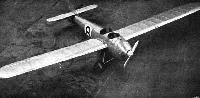
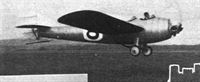
Регистрационный номер: G-EBJU [12] THE SHORT "SATELLITE," BRISTOL "CHERUB" ENGINE: Three-quarter front view from above.
-
Flight 1924-09 / Flight
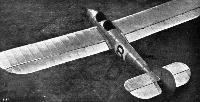
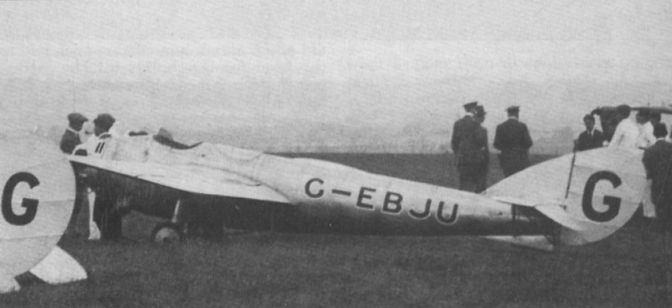
Регистрационный номер: G-EBJU [12] THE SHORT "SATELLITE": Three-quarter rear view, from above.
-

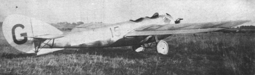
Flight 1926-09 / Flight
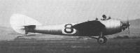
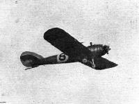
Регистрационный номер: G-EBJU [12] No.15. THE SHORT "SATELLITE": This machine has been entered by the Seven Aeroplane Club.
-

Aeroplane Monthly 1985-11 / R.Riding - Short Satellite /British pre-war ultralights/ (56)
Регистрационный номер: G-EBJU [12] Lankester Parker, with passenger, attempts to take off from Lympne in September 1924. With two up the aircraft would barely leave the ground when powered by the direct drive Cherub I.
-
Aeroplane Monthly 1985-11 / R.Riding - Short Satellite /British pre-war ultralights/ (56)
Регистрационный номер: G-EBJU [12] Lankester Parker flying the Satellite solo at Lympne in September 1924.
-
Flight 1939-04 / Flight
Регистрационный номер: G-EBJU [12] The Short Satellite with Bristol Cherub engine was the first all-metal light aeroplane. It appeared in 1924.
-
Flight 1924-09 / Flight
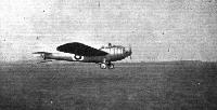
Регистрационный номер: G-EBJU [12] The Short "Satellite" starting on a flight.
-
Flight 1924-10 / Flight
Регистрационный номер: G-EBJU [12] The Short "Satellite" monoplane, making a trial flight at Lympne.
-
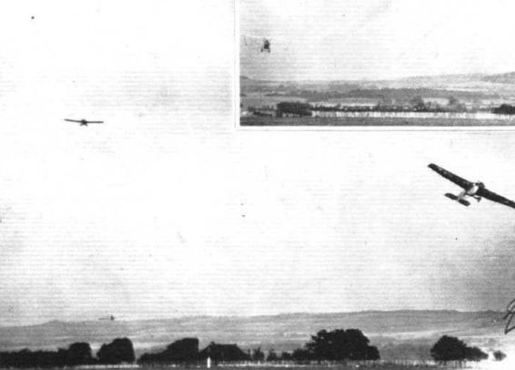
Flight 1926-09 / Flight
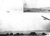
Регистрационный номер: G-EBJU [12] THE RACE FOR THE GROSVENOR CHALLENGE CUP: No less than 21 machines faced the starter for this race, a record number. The result was that machines frequently got bunched together at the turning points. Our photograph show one of some such incidents. In 3 may be recognised the Short "Satellite," the Parnall "Pixie" and the R.A.E. "Hurricane."
Другие самолёты на фотографии: Parnall Pixie - Великобритания - 1923RAE Hurricane - Великобритания - 1923
-

Aeroplane Monthly 1985-11 / R.Riding - Short Satellite /British pre-war ultralights/ (56)
Регистрационный номер: G-EBJU [12] The Satellite was acquired by the Seven Aero Club in 1926, re-engined with a 40 h.p. ABC Scorpion II engine and fitted with a Fairey-Reed metal propeller.
-
Aeroplane Monthly 1985-11 / R.Riding - Short Satellite /British pre-war ultralights/ (56)
Регистрационный номер: G-EBJU [12] The Satellite’s fuselage during construction with Cherub I installed.
-

Aeroplane Monthly 1985-11 / R.Riding - Short Satellite /British pre-war ultralights/ (56)
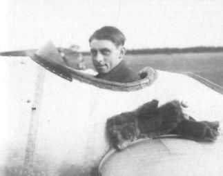
Регистрационный номер: G-EBJU [12] Short’s test pilot John Lankester Parker seated in the Satellite at Lympne in September 1924. Note the fur mittens lying on the wing.
-
Flight 1924-09 / Flight
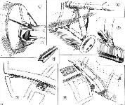
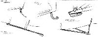
SOME SHORT CONSTRUCTIONAL DETAILS: 1. The very neat engine mounting for the Bristol "Cherub." This mounting should be particularly good in respect of torsional stresses. 2. The oleo undercarriage. 3. Attachment of tail skid fixed end to fuselage. 4. The renewable shoe on the free end of the tail skid. 5. An aileron hinge. 6. The port wing root showing inspection doors giving access to wing attachments. The ailerons are operated by torque tubes.
-
Flight 1924-10 / Flight
A FEW UNORTHODOX TAIL SKIDS ON LYMPNE MACHINES: The Bristol is a leaf-spring and the Avro a bent tube. The Short has a long straight, tubular skid, and the Westlands a horizontal Vee with compression spring to the stern-post.
Другие самолёты на фотографии: Avro Avis / Type 562 - Великобритания - 1924Bristol Brownie / Type 91 - Великобритания - 1924Westland Wood Pigeon - Великобритания - 1924
-
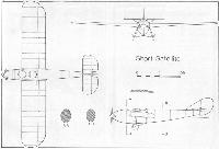
Flight 1924-07 / Flight
Short Two-seater Light-plane Bristol "Cherub" Engine
-


- Фотографии