
 Wiki
Wiki 
Варианты
- ANEC - I / II - 1923 - Великобритания
- Beardmore - W.B.XXIV Wee Bee - 1924 - Великобритания
Flight, September 1924
THE BEARDMORE "WEE BEE I" LIGHT MONOPLANE (No. 4)
Bristol "Cherub" Engine
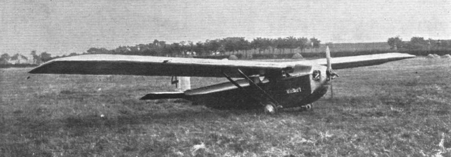
THE first machine to be designed by Mr. W. S. Shackleton, after he joined Wm. Beardmore and Co., Ltd., was the light monoplane shown in the accompanying illustrations. It is, of course, only natural that there should be similarities between the "Wee Bee I," as the Beardmore light monoplane has been christened, and the A.N.E.C. monoplane, for whose design also Mr. Shackleton was responsible. There are, however, several differences between the two machines, quite apart from the difference in engines.
The W.B. XXIV, to give the machine its proper series number, is a thick-wing monoplane of very clean design, every effort having been made to reduce to a minimum any projections which might adversely affect the performance. The machine is not, however, a cantilever monoplane, as its wing is divided in the centre and each plane is braced by two struts from the lower longerons of the fuselage. Apart from this fact, however, there is no external bracing anywhere, either in the tail or in the undercarriage. The cross-section of the fuselage is the smallest possible to reduce head resistance, and altogether the "Wee Bee I" represents a very serious attempt at aerodynamic perfection. That the striving of the designer has not been in vain appears to be indicated by the performance curves given on page 594, to which reference will be made again later. The top speed is extremely good, and the minimum horse-power required is so low that the machine probably has a greater reserve of power than any other in the competitions.
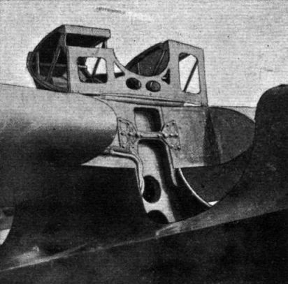
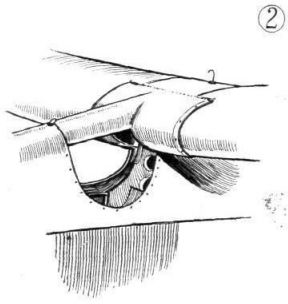
The fuselage is built on six spruce longerons with formers or bulkheads of spruce and three-ply, the whole being covered with 1/16-inch birch three-ply. The deck fairing, instead of being arched, as is usually done, is "hollow-ground," and thus conforms roughly to the shape of a man's head and shoulders. Thus, the pilots are stream-lined, while, by moving their heads slightly to right or left, they can look past the fairing. The photographs and general arrangement drawings show this deck fairing admirably. The two cockpits are arranged one aft of the wing, or rather aft of the rear spar, and one ahead of the front spar. There is a square opening in the trailing edge through which the pilot enters, and which is covered during flight by a celluloid window. The front cockpit is entered by swinging upwards a small hinged portion of the leading edge of the wing. When the pilot is in place, the leading edge is brought down in line with the rest of the wing and locked in position. The view from both cockpits is very good, particularly so from the front one, where there is practically no obstruction if the pilot leans his head slightly to left or right. For landing, particularly, this position seems to be almost ideal.
The controls and instruments are of usual type, and the machine is, of course, capable of being flown from either seat. When being flown solo, with the pilot in the front seat, a small weight in the rear cockpit is probably necessary for trimming purposes. In the case of the pilot-owner this weight would, presumably, be made up of the owner's luggage, in which case the machine would not be carrying any unnecessary load.
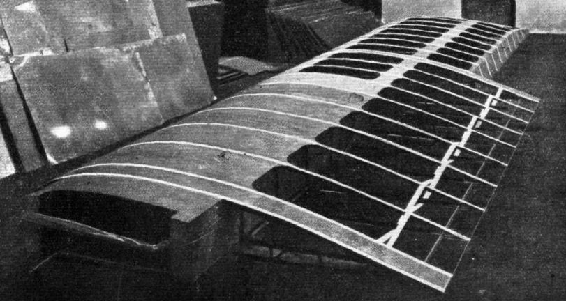
The monoplane wing is of fairly orthodox construction in that it has the usual two main spars, of box section with three-ply walls. Both flanges and walls taper in thickness towards the tips, being proportioned to the shear and bending moments along the span. There is no internal drag bracing in the wing, at least in the ordinary sense of the term. This function is performed by the three-ply covering which extends along the entire leading edge, up to the front spar, and near the root, as far out as the strut attachments: in fact, this three-ply covering extends back to behind the rear spar.
The ailerons are of large aspect ratio, and are hinged to a false rear spar or stringer. They are operated by crank levers through short push-and-pull rods, and no control pulleys are employed.
The tail unit is also of interest, and shows to some extent the same characteristics as those illustrated in the case of the "A.N.E.C. II." The fin is in two sections, located by dowel pegs, and the tail plane has but a single spar, built integral with the rear portion of the fin. The front portion of the fin is integral with the fuselage structure. The elevator is hinged along the top edge, and the opening underneath is covered with a Duralumin flap so that there is no gap at the hinge line.
As in the case of the ailerons, the elevator is operated by a short push-and-pull rod, from cranks on a lay shaft.
The undercarriage consists simply of a single bent tube passing through the fuselage and anchored by suitable fittings at the sides. The axle is of chrome nickel steel, and specially designed to allow of sufficient flexibility to absorb landing shocks. It is supported in the fittings on trunnions, which allow it to flex freely. One trunnion is rigidly fixed to the axle so as to resist torque loads and in order to locate the axle endwise. The trunnion on the opposite side takes uploads only, and is free to slide on the axle.
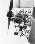
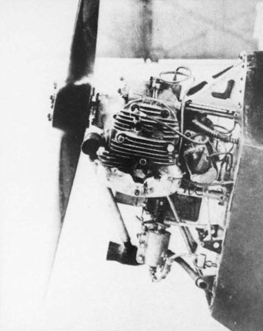
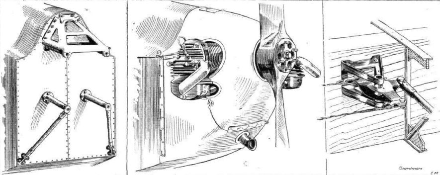
The mounting of the Bristol "Cherub" engine is rather ingenious, and should prove very satisfactory in practice. The weight of the engine is taken by a pyramid support of sheet Duralumin, while the vertical position is maintained by two lower struts, also of Duralumin. The lower supports are steadied by diagonal tubes (steel) running to the lower corners of the engine bulkhead. The engine is readily accessible, and can be removed from the machine by undoing four bolts, and, of course, the usual petrol and oil connections, etc. A cowling surrounds the engine, all but the cylinder heads. The entry for the air is, it will be seen, particularly clean and unobstructed and carries out the designer's idea of saving in head resistance.
With reference to performance, although this will be definitely proved or disproved during the competitions, it may be of interest to give the estimated performance figures, and we consequently publish a set of curves from which the estimated performance can be seen. The first thing that strikes one is the extraordinarily low horse-power required, and the fact that this does not necessarily diminish with the flying speed. Thus, the minimum thrust horse-power of about 5 1/2 b.h.p. occurs at an angle of 6 degrees, corresponding to a speed of 41 m.p.h. It is of interest to note that the smallest horse-power figure coincides with the angle (6 degrees), at which L3/D2 is a maximum. This angle also gives the lowest rate of descent in gliding, as those of our readers will remember who studied FLIGHT during the interesting summer of 1922. The angle of attack and corresponding speed giving highest mileage per gallon also gives the best gliding angle. It is at this angle (3 degrees) that the machine flies horizontally with the lowest propeller thrust, and at which the speed horse-power ratio attains a maximum value. It will be observed that the maximum value of L/D occurs at an angle of 3 degrees, and is as high as 16-8. This is, of course, an extraordinarily good figure, and if there is any doubt as to whether all the L/D values estimated are too high, we might point out that on a test flight the machine reached a top speed of 88 m.p.h. as registered by the speed indicator. There is, of course, still the possibility that the indicator was somewhat in error, but at any rate there does seem to be every reason to expect that the estimated top speed of 86 m.p.h. will be attained. A time-to-altitude chart gives the climb of the "Wee Bee I," and this seems to be in keeping with the other performance figures. Altogether the machine should prove a formidable opponent, and its performance in the competitions will be watched with more than ordinary interest.
- Flight, September 1924
THE BEARDMORE "WEE BEE I" LIGHT MONOPLANE (No. 4)
Фотографии

-
Flight 1926-09 / Flight
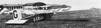
Регистрационный номер: G-EBJJ [21], VH-URJ [21] THE 1924 WINNER: The Beardmore "Wee Bee," with Bristol "Cherub," which, piloted by Maurice Piercey, gained first prize.
-
Aeroplane Monthly 1985-05 / P.Jarrett - Beardmore WB.XXIV Wee Bee 1 /British pre-war ultralights/ (50)
Регистрационный номер: G-EBJJ [21], VH-URJ [21] “Bill” Shackleton (left) and Piercey discuss tactics at Lympne.
-
Air-Britain Archive 1995-04 / Extracts
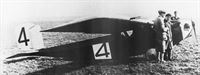
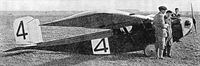
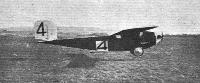
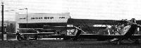
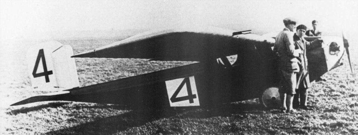
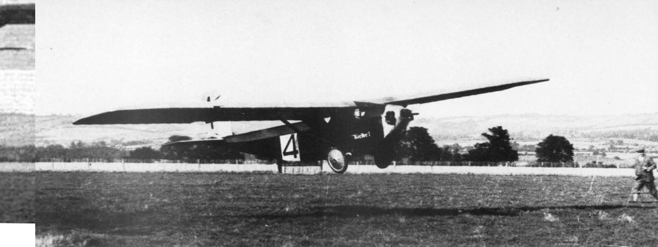
Регистрационный номер: G-EBJJ [21], VH-URJ [21] The Beardmore Wee Bee won the 1923 Air Ministry lightplane trials and is seen at the time wearing No.4 - see extract for 9.9.49.
Aeroplane September 9th 1949 * p.353 - Recently discovered in Australia was the 1924 Beardmore Wee Bee ultralight exported there in the 30s. It had been in store since 1939 but was in good condition and was being restored by Vincent Boyes of Victoria who hopes to have it flying soon.
A: 9.9.49 p.353 - The only Beardmore Wee Bee (32 hp Bristol Cherub) was built for the Air Ministry 2-seater lightplane trials held at Lympne in 1924. It carried the number 4 and won the £2 500 first prize. Registered G-EBJJ by 8.25, it did not receive its CofA until 4.3.30. In 1933 it went to Australia and became VH-URJ. After its 1949 resurrection it was obtained by Vincent Boyes. It was reported to have crashed, but whether this was on its first flight after rebuild (as the lack of reports of other flying suggests) is not known. After the crash it was grounded and for some time was used for Boyes' children to play in, a sad end for an aircraft that made its mark in history. -
Aeroplane Monthly 1985-05 / P.Jarrett - Beardmore WB.XXIV Wee Bee 1 /British pre-war ultralights/ (50)
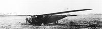
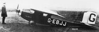
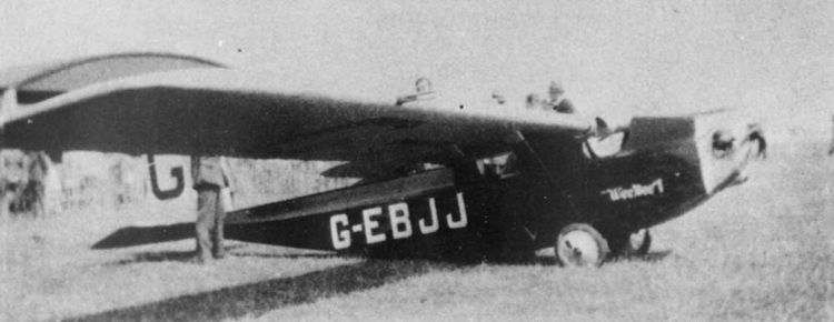
Регистрационный номер: G-EBJJ [21], VH-URJ [21] The Wee Bee at Dalmuir in its first form, with unbalanced rudder.
-
Flight 1924-10 / Flight
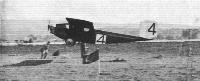
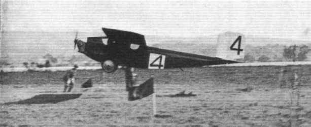
Регистрационный номер: G-EBJJ [21], VH-URJ [21] The Beardmore "Wee Bee" monoplane (Bristol "Cherub") taking off in the eliminating trials at Lympne.
-
Flight 1930-07 / Flight
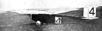
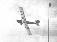
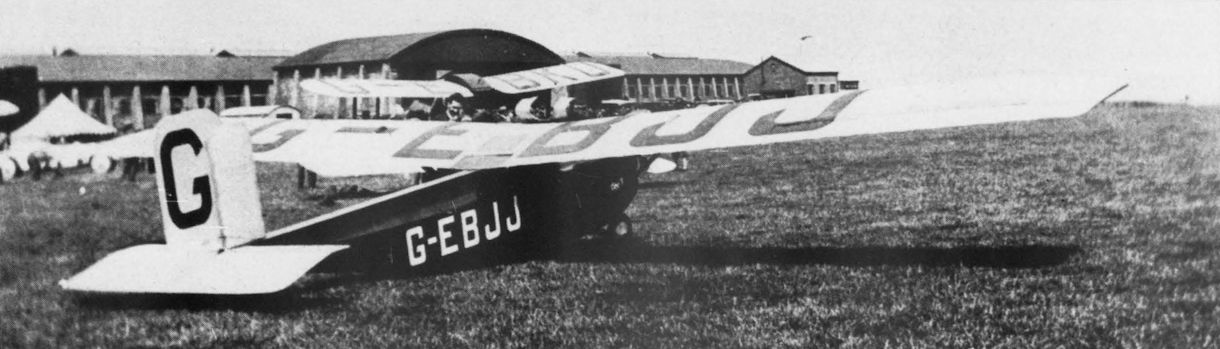
Регистрационный номер: G-EBJJ [21], VH-URJ [21] ALMOST A GLIDER: The Wee Bee, which appeared again at the Sherburn Meeting on July 13. This was one of the forerunners of the present day light aeroplane.
-
Flight 1924-10 / Flight
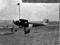
Регистрационный номер: G-EBJJ [21], VH-URJ [21] LOW-SPEED FLYING AT LYMPNE: 3, Piercey on the Beardmore "Wee Bee."
-
Flight 1924-10 / Flight
Регистрационный номер: G-EBJJ [21], VH-URJ [21] THE WINNER: The Beardmore "Wee Bee I," Bristol "Cherub" engine, on which Piercey won first prize in the Lympne Light 'Plane competitions.
-

Aeroplane Monthly 1985-05 / P.Jarrett - Beardmore WB.XXIV Wee Bee 1 /British pre-war ultralights/ (50)
Регистрационный номер: G-EBJJ [21], VH-URJ [21] Makers of light plane history. The picture shows the Beardmore Wee Bee, with Bristol "Cherub," which won the Lympne light plane competition in 1924.
The Wee Bee in action at the 1924 Lympne trials, Maurice Piercey in charge. -

Aeroplane Monthly 1978-02 / Personal album
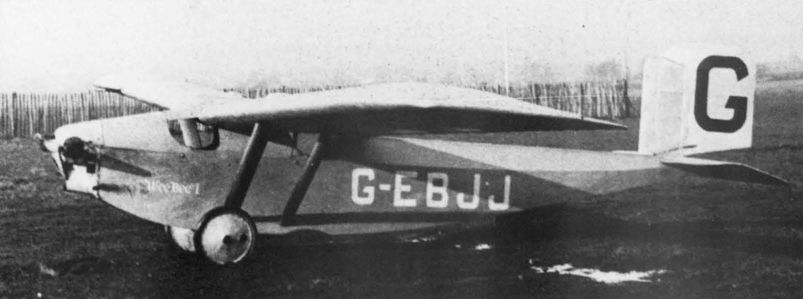
Регистрационный номер: G-EBJJ [21], VH-URJ [21] Beardmore W.B.XXIV Wee Bee I G-EBJJ was built to compete in the 1924 Lympne Light Aeroplane Trials, and won the main prize in the hands of M. Pearcy. Weighing only 840lb with two passengers, the Wee Bee had a maximum speed of 87 m.p.h. on a 32 h.p. Bristol Cherub.
-
Aeroplane Monthly 1985-05 / P.Jarrett - Beardmore WB.XXIV Wee Bee 1 /British pre-war ultralights/ (50)
Регистрационный номер: G-EBJJ [21], VH-URJ [21] At Lympne in August 1926.
-
Aeroplane Monthly 1985-05 / P.Jarrett - Beardmore WB.XXIV Wee Bee 1 /British pre-war ultralights/ (50)
Регистрационный номер: G-EBJJ [21], VH-URJ [21] The Wee Bee on trial at Martlesham Heath, early in 1926
-

Aeroplane Monthly 1985-05 / P.Jarrett - Beardmore WB.XXIV Wee Bee 1 /British pre-war ultralights/ (50)
Регистрационный номер: G-EBJJ [21], VH-URJ [21] At Whitchurch Bristol, 1932-33.
-
Flight 1925-08 / Flight
Регистрационный номер: G-EBJJ [21], VH-URJ [21] Kingwill on the Beardmore "Wee Bee."
-
Flight 1932-06 / Flight
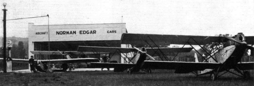
Регистрационный номер: G-EBJJ [21], VH-URJ [21] Mr. Norman Edgar's depot with three of his Parnall "Elfs" and a "Wee Bee" lined up for inspection.
Другие самолёты на фотографии: Parnall Elf - Великобритания - 1929
-
Aeroplane Monthly 1985-05 / P.Jarrett - Beardmore WB.XXIV Wee Bee 1 /British pre-war ultralights/ (50)
Регистрационный номер: VH-URJ [21], G-EBJJ [21] In Australia as VH-URJ, circa 1934.
-
Aeroplane Monthly 1985-05 / P.Jarrett - Beardmore WB.XXIV Wee Bee 1 /British pre-war ultralights/ (50)
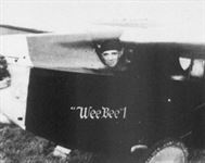
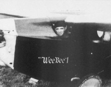
Регистрационный номер: G-EBJJ [21], VH-URJ [21] Maurice Piercey peers from his confined front cockpit during the Lympne trials. The view forward was good, owing to the “hollow-ground” top decking.
-

Aeroplane Monthly 1985-05 / P.Jarrett - Beardmore WB.XXIV Wee Bee 1 /British pre-war ultralights/ (50)
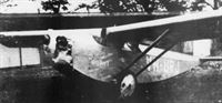
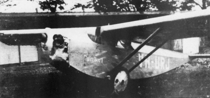
Регистрационный номер: G-EBJJ [21], VH-URJ [21] How he got in - the leading edge folded back to permit entry.
-
Aeroplane Monthly 1985-05 / P.Jarrett - Beardmore WB.XXIV Wee Bee 1 /British pre-war ultralights/ (50)
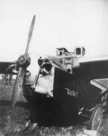
Регистрационный номер: G-EBJJ [21], VH-URJ [21] The installation of the 32 h.p. Bristol Cherub engine.
-

Flight 1924-09 / Flight
Регистрационный номер: G-EBJJ [21], VH-URJ [21] This photograph gives a good idea of the wing construction of the Beardmore "Wee Bee."
-

Flight 1924-10 / Flight
Регистрационный номер: G-EBJJ [21], VH-URJ [21] The "Office" of the Beardmore "Wee Bee I" is reached by hinging back the central portion of the leading edge, as shown in this photograph.
-
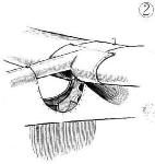
Flight 1924-10 / Flight
CONSTRUCTIONAL DETAILS OF LIGHT 'PLANES AT LYMPNE: (2) Front cockpit covering of Beardmore "Wee Bee I." Leading edge and top cover hinge back for getting into and out of cockpit.
-

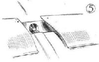
Flight 1924-10 / Flight
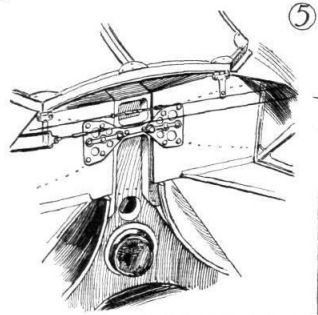
CONSTRUCTIONAL DETAILS OF LIGHT 'PLANES AT LYMPNE: (5) View into rear cockpit of Beardmore "Wee Bee I," showing spar attachment to top of fuselage This cockpit is covered by a hinged window of celluloid.
-
Flight 1924-10 / Flight
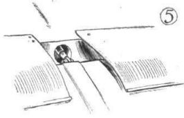
SOME MORE CONSTRUCTIONAL DETAILS FROM LYMPNE: (5) The aileron gap in the "Wee Bee I" is covered with aluminium strips. The aileron is hinged at bottom edge, and is operated direct from upper edge by a pull-and-push rod.
-
Flight 1925-08 / Flight
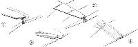
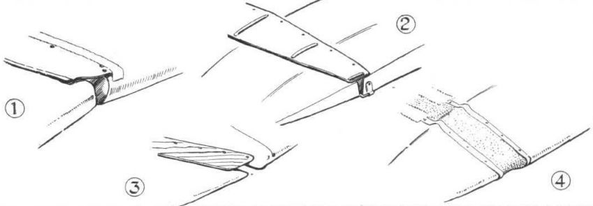
"STOP THAT LEAK": Different methods of closing the gap between rear spar and aileron in some of the Lympne machines. 1. In the Beardmore "Wee Bee" an aluminium strip is used with edges turned over for stiffening purposes. The front edge is covered by fabric strip doped on. 2. In the A.N.E.C, an aluminum strip is used, stiffened by fore-and-aft corrugations, while in 3, the Parnall "Pixie II" three-ply is employed, and in 4, the Cranwell monoplane, rubber strip. This was later removed as it tended to cause the controls to work stiffly.
Другие самолёты на фотографии: ANEC I / II - Великобритания - 1923Comper Cranwell III / CLA.3 - Великобритания - 1925Parnall Pixie - Великобритания - 1923
-
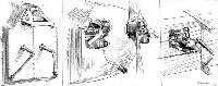
Flight 1924-09 / Flight
BEARDMORE CONSTRUCTIONAL DETAILS: On the left a sketch, showing the very neat engine mounting. Centre: The Bristol "Cherub" in place and cowled in. On the right an aileron crank with push-and-pull rod.
-
Flight 1924-09 / Flight
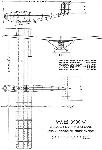
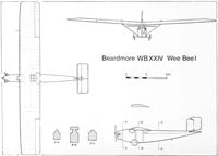
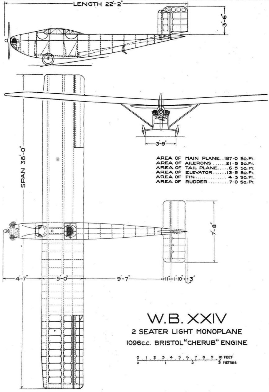
W.B.XXIV 2-seater Light Monoplane 1096 c.c. Bristol "Cherub" Engine
-
Aeroplane Monthly 1985-05 / P.Jarrett - Beardmore WB.XXIV Wee Bee 1 /British pre-war ultralights/ (50)
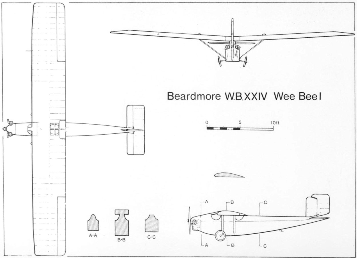
Beardmore E.B.XXIV Wee Bee I


- Фотографии