
Фотографии

-

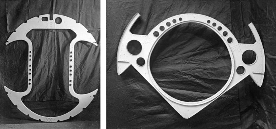
LEFT The first image from the Hawker material shows a pressed light-alloy fuselage frame from the area of the wing-root intakes, illustrating the recesses where ducting will guide air to the Rolls-Royce Nene engine. The frame has been photographed upside-down; when installed in the airframe, the flat inside edge should be at the base. Notches in the outer edges of the frame are to accommodate the fuselage’s longerons and stringers.
RIGHT In terms of construction this light-alloy fuselage frame is conventional, although its shape is unusual. The “V” shape in the lower part of the frame was adopted to create space within the fuselage for the main undercarriage bay. The N.7/46’s thin wing left less space for the undercarriage than in previous piston-engined designs, while the large-diameter engine and the thicker wing roots required for the intakes left space free just aft of the engine, which Hawker used to house the mainwheels when retracted. The space in the upper half was for a saddle-type fuel tank sitting over the aft end of the engine. The wings were too thin to incorporate fuel tanks.Самолёты на фотографии: Hawker Sea Hawk - Великобритания - 1947
-

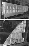
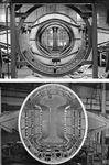
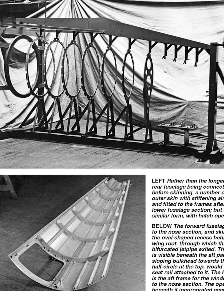
TOP The rear fuselage was relatively simple compared with the central and nose sections, both of which had to incorporate a great deal of equipment and house major items such as the engine and cockpit. Here the light ring-frames have been positioned in the jig, running aftwards from left to right. Note the transition from those furthest forward, which are of a broadly circular cross-section, to much thinner oval-section frames at the aft end. The semi-monocoque rear fuselage structure consisted of a total of 15 of these light frames and 16 stringers supporting the skin.
BOTTOM Rather than the longerons and stringers for the rear fuselage being connected directly to the frames before skinning, a number of pre-formed sections of outer skin with stiffening already attached were built up and fitted to the frames after their assembly. This is the lower fuselage section; but all the skin panels were of similar form, with hatch openings pre-cut, as seen here.Самолёты на фотографии: Hawker Sea Hawk - Великобритания - 1947
-

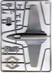
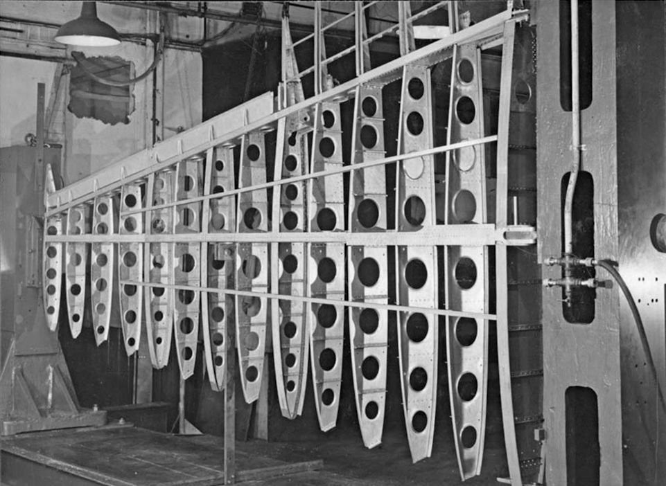
The mainplane structure of the N.7/46, which was a notable advance on the preceding Sea Fury in several respects. The almost total lack of stringers is evident here, with stiffness imparted instead through a thicker-gauge skin, a practice learned from American manufacturers during British engine genius Roy Fedden’s mission to the USA during the Second World War. The straight leading and trailing edges simplified manufacturing, while the "high-speed" aerofoil - with maximum thickness at around 40 per cent chord (note how far aft the main spar is) and a 9-5 per cent thickness to chord ratio (compared with 14 per cent for the Sea Fury) - significantly improved performance.
Самолёты на фотографии: Hawker Sea Hawk - Великобритания - 1947
-
TOP An N.7/46 elevator in its construction jig, showing generally similar construction to the mainplanes. Note the elevator’s curved outboard end; this feature was only included on the prototypes, and production elevators were square-ended. The forward edge shows the balance and flange for the aerodynamic "seal strip", which prevented air leaking between the upper and lower surfaces of the tailplane.
BOTTOM The fin, with its starboard face skinned, showing its longitudinal and vertical ribs. The slot in the trailing edge housed the rudder’s balance tab. This is only the upper part of the fin; the lower part was integral with the fuselage and the curvature of the lower edge corresponds to the upper surface of the tailplane.Самолёты на фотографии: Hawker Sea Hawk - Великобритания - 1947
-
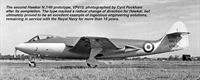
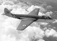
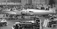
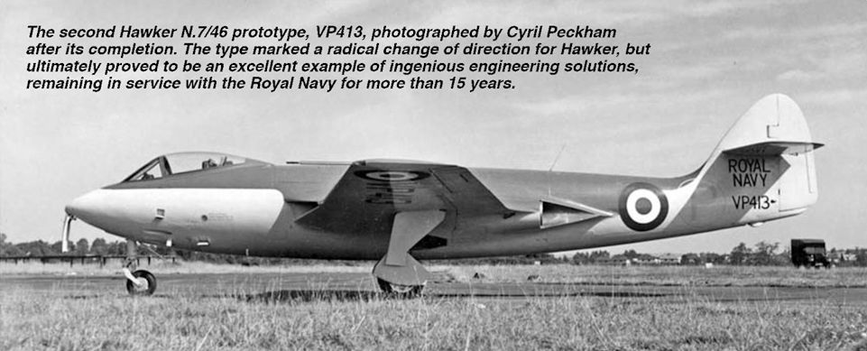
Регистрационный номер: VP413 [2] The second Hawker N.7/46 prototype, VP413, photographed by Cyril Peckham after its completion. The type marked a radical change of direction for Hawker, but ultimately proved to be an excellent example of ingenious engineering solutions, remaining in service with the Royal Navy for more than 15 years.
Самолёты на фотографии: Hawker Sea Hawk - Великобритания - 1947
-
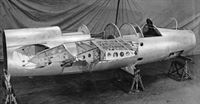
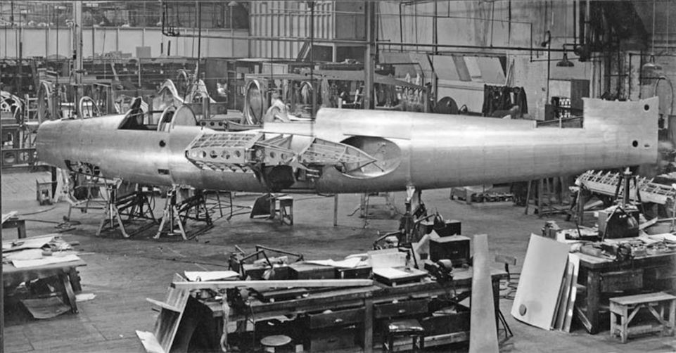
The forward fuselage has now been joined to the nose section, and skinning has begun. Note the oval-shaped recess behind the trailing edge of the wing root, through which the starboard section of the bifurcated jetpipe exited. The main undercarriage bay is visible beneath the aft part of the wing-root. The sloping bulkhead towards the nose, with the protruding half-circle at the top, would have the pilot’s ejection-seat rail attached to it. The half-hoop at the forward end is the aft frame for the windscreen, which was integral to the nose section. The open rectangular panel beneath it incorporated access to the guns’ blast tubes.
Самолёты на фотографии: Hawker Sea Hawk - Великобритания - 1947
-
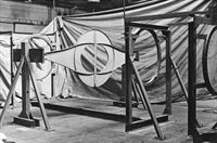
With the engine in the centre of the fuselage, the mainspar could not pass directly through, so a ringframe had "outriggers" attached, taking the loads from the outer wing spars, in this case the rear spar that carried the flaps and ailerons. The central pillar bisecting the ring-frame passed between the two branches of the bifurcated jetpipe that Hawker and Rolls-Royce developed for the N.7/46. The diagonal flanges on the ring-frame indicate the inner surface of the undercarriage bay, of which this frame formed the aft face. The frame seen (from the rear) in this photograph has been placed in the main fuselage construction jig. The fuselage was constructed in three main sections - the central part, as seen here, the nose section and the rear fuselage and tail section.
Самолёты на фотографии: Hawker Sea Hawk - Великобритания - 1947
-
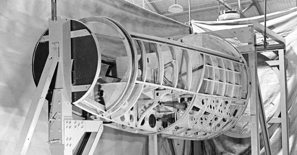
TOP The central fuselage further along in its construction in the jig, looking forward. More frames have been added, forming the backbone of the aircraft. This section would eventually contain the engine and its associated intake trunking, the frames with their recesses for which, as in the first photograph, may be seen at the forward end of the assembly. This sub-assembly would also contain the engine exhaust system, the main undercarriage bays and form the wing/fuselage connection. It demonstrated the biggest difference from pistonengine practice in this transitional jet design.
BOTTOM The same assembly seen from the forward end, now with the skin attached, and the wing root added. This image shows how the intake air was guided from the wing-root intake, the shape indicated by the bracing rods between the fuselage and the large inner wing rib, into the central fuselage to feed the Nene engine’s prodigious (for the time) mass-flow requirements.Самолёты на фотографии: Hawker Sea Hawk - Великобритания - 1947
-
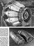
TOP The Rolls-Royce B.41 engine, known in production as the Nene, was essentially a version of the same company’s Welland, scaled-up and improved via lessons learned from the USA’s General Electric/Allison J33. The Hawker P.1035/P.1040 was designed around the engine, which became the most powerful jet in production for a spell in the late 1940s. The engine is seen here from the port rear side. A manifold would be attached to the aft end of the engine, to which each jetpipe would be fitted. The jointed tubes at the top of the engine were part of the N.7/46 installation; the sockets at the rear attached to fittings on a ring frame inside which the engine sat.
BOTTOM Parts of the characteristic twin jetpipes, central to the N.7/46’s design, developed by Rolls-Royce and Hawker specifically for the type. Note how they curve, initially splaying outwards before bending inward to direct the jetflow more in line with the aircraft’s axis. The rear of the jetpipe is closest to the camera on the left-hand item (marked "STBD", i.e. starboard) and furthest from the camera on the right-hand jetpipe.Самолёты на фотографии: Hawker Sea Hawk - Великобритания - 1947
-
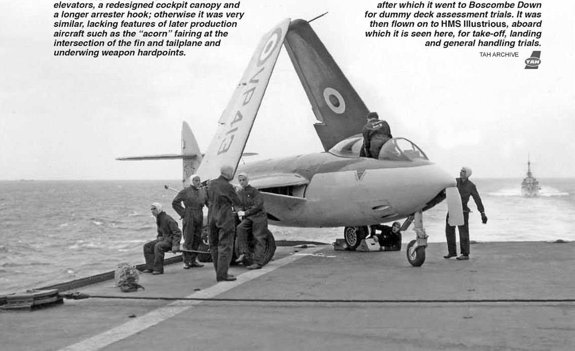
Регистрационный номер: WF144 The finished article - a fine Cyril Peckham study of WF144, the second production example of the Sea Hawk F Mk 1. Only 35 Sea Hawks were produced by Hawker (apart from the prototypes) before production moved to Armstrong-Whitworth at Baginton. This aircraft differed from the prototypes by having square-ended elevators, a redesigned cockpit canopy and a longer arrester hook; otherwise it was very similar, lacking features of later production aircraft such as the “acorn” fairing at the intersection of the fin and tailplane and underwing weapon hardpoints.
Самолёты на фотографии: Hawker Sea Hawk - Великобритания - 1947
-
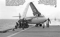
Регистрационный номер: VP413 [2] Although it is not specified in the material, it is likely that the aircraft seen being constructed in the preceding photographs was the second N.7/46 prototype, VP413 - which, unlike the first, included folding wings, catapult spools and full gun armament. The aircraft made its maiden flight on September 3, 1948, after which it went to Boscombe Down for dummy deck assessment trials. It was then flown on to HMS Illustrious, aboard which it is seen here, for take-off, landing and general handling trials.
Самолёты на фотографии: Hawker Sea Hawk - Великобритания - 1947
-
Регистрационный номер: VP422 The pre-skinned rear fuselage section has now been mated to the central fuselage, and the main structure is complete. The base of the fin was integral with the fuselage, as the tail was of cruciform design with the tailplane mid-mounted on the fin - a compromise between raising it clear of the jetwash and avoiding the higher weight associated with a T-tail. Note the frames of another N.7/46 in their jigs in the background - possibly the third prototype, VP422.
Самолёты на фотографии: Hawker Sea Hawk - Великобритания - 1947
-

The forward fuselage section from a port three-quarter view, with the majority of the frames now in place. Armament was included on the second and third N.7/46 prototypes; VP413 was the first to be equipped with the planned four 20mm Hispano cannon in the underside of the nose, two of which may be seen midway along the section. Note the hollow in the frames adjacent to the gun bay to allow clearance for the cannon’s blast tubes. The upper half of the sub-assembly is open, as this is where the cockpit will ultimately be sited.
Самолёты на фотографии: Hawker Sea Hawk - Великобритания - 1947
-
Самолёты на фотографии: Hawker Sea Hawk - Великобритания - 1947


Статьи
- -
- A.Delalande, T.Cooper - An eye for an eye
- C.Goss - Last days of the Condor
- E.Wild - Hijack hijinks!
- G.Baughen - A Brief History of the Future
- J.Forsgren - The flying darkroom
- J.Matos - Nao obrigado!
- M.Bearman - The Whirlwind becalmed
- M.Wickstead - A sky full of frontiers
- M.Willis - How to build a Sea Hawk
- N.Stroud - Fire in the belly
- N.Stroud - Heathrow. The Roaring Forties /The John Stroud Archive/
- P.Davidson - Off the Beaten Track...
- P.Jarrett - Lost & Found
- P.Jarrett - The Blue Falcon
- R.Riding - Three deadly minutes