

Flight, August 1928
THE ARMSTRONG WHITWORTH "STARLING
Armstrong-Siddeley Supercharged "Jaguar" Engine
AMONG the batch of single-seater fighters recently produced, the Armstrong-Whitworth "Starling" is of particular interest not only on account of its general aerodynamic design but also because of its all-metal construction, a type of aircraft construction in which Sir W. G. Armstrong Whitworth Aircraft, Ltd., have specialised for a considerable time, and one form of which has become extremely well known in the "Siskin," of which large numbers have been and are being built for the British Royal Air Force.
The "Starling" has been designed for use not only as a day fighter but also as a night fighter, being equipped with the usual navigation lights, Holt flares, etc., although in our photographs it is shown with the short exhaust pipes of the day fighter, i.e., without the collector ring commonly used on night fighters to prevent the open exhaust being seen in the dark.
In general design the "Starling" resembles previous types of Armstrong Whitworth machines, such as the "Siskin" and "Atlas." That is to say, one would identify the machine as an Armstrong Whitworth anywhere, although a closer inspection at once reveals considerable differences. Of the "sesquiplane" type, which chiefly the "Siskin" has made familiar in this country, the "Starling" is characterised by a large top plane and a much smaller bottom plane, with the interplane struts raked at a pronounced angle.
The wing section employed is a biconvex one, and more particularly that known as R.A.F. 30, which is symmetrical, i.e., without centre-line camber. In the design of the machine advantage has been taken of this fact by placing the top plane at a larger angle of incidence to the centre line than is usually found. This was desirable in order to get a large angle with the tail skid on the ground, the angle of no lift of the symmetrical wing section, of course, being at 0° incidence. But in placing the top plane at this large angle the pilot's view is at the same time improved, as his eyes are approximately level with the centre-line of the section, so that he can look both above and below the wing. Added to this is the fact that although the top plane is built in two halves, there is not the usual cabane for the support of the wing roots, the upper wings being supported from the body by outwardly-raked struts. This absence of a cabane also slightly improves the view, while the slight sagging of the fabric covering over the centre-line joints in the top spars has the effect of slightly reducing the wing thickness, thus again improving the view.
Although a structural rather than an aerodynamic feature, reference may be made here to the somewhat unusual form of wing bracing employed, and which has been made possible by the use of the symmetrical wing section: the main lift wires, instead of running to front and rear spars, as is usually done, are both taken to a point on the front spar, the rear spar having no lift wire. This arrangement, which at first sight looks a little alarming, has been chosen so as to concentrate as much of the wing strength as possible in the front spar, which is located in a part of the wing section which has ample depth to accommodate it, the rear spar being quite a light affair, and little more than a strong stringer. In the more usual wing section such an arrangement could not well have been used, the travel of the centre of pressure under certain conditions throwing a considerable load on the rear spar. With the RAF 30 section, however, the c.p. is almost stationary, and is, moreover, situated fairly far forward, so that this form of bracing has been rendered possible. Any small loads that may be thrown on the rear spar are transferred to the front bay bracing via the interplane struts, which are of "N" formation.
While discussing the use of R.A.F. 30 with Mr. Lloyd, Armstrong Whitworth's chief designer, a rather interesting point came to light. In the model form, the maximum lift coefficient of this section is not very high (about 0-45 or so at VL = 100), but the section appears for some reason to be subject to considerable scale effect, so that the full scale lift coefficient of the "Starling" is in the neighbourhood of 0-6, which enables this section to be used for a reasonably heavy wing loading without the landing speed becoming unduly high. The minimum drag is low, the section thus being suitable for a wide speed range.
Constructional Features
Mention has already been made of the fact that the "Starling" is of all-metal construction. This is not strictly true, since the wing ribs are of wood. With that one exception, however, the machine is built entirely of metal as regards its structural parts, although the covering is in the form of doped fabric.
The fuselage, like the wings, is of steel construction, but whereas the wing spars are built up from rolled and drawn strip, the fuselage members are in the form of circular section steel tubes. At the fuselage joints the longerons are reinforced with tubular sleeves at the points where the longerons are pierced by the bolts. The sleeves are merely lengths of tubing of a size to slide over the longerons. The general arrangement of a typical "Starling" fuselage joint is shown in one of our sketches. Bracing is by tie rods in the usual way. To the main fuselage structure is added a fairing composed of hoops or formers of channel section to which are riveted stringers made from rolled strip. These also are shown by sketches. The fuselage is built in two main sections, front and rear, bolted together aft of the pilot's seat.
The wing construction takes the form of steel box spars carrying wood ribs, the spars being composed of webs and flanges rolled to corrugated sections from flat strip and riveted together. The wood ribs are held to the spars without any form of fastening, the blocks in front of and behind the bars being so proportioned that a slight pressure on the spar flanges is produced, which is sufficient for locating the ribs. The details of the rib posts and blocks are shown in a sketch, from which it will be seen that posts and blocks are taped together. The front spars are of large dimensions, although even so they do not "fill" the wing section, while the rear spars are, as previously mentioned, relatively small and light. The normal spar flange is a single thickness, corrugated for stiffness, but locally, such as at the ends and at the strut attachment points, several laminations are employed, that nearest the main flange being the longest, thus gradually tapering off the thickness of metal. The internal struts of the drag bracing are circular-section steel tubes. The two halves of the top plane are joined together on the centre line by fork-end joints, the small gap left between the two end ribs being covered over with fabric.
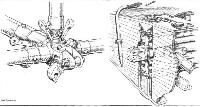
The lower wings are joined to the fuselage longerons in the manner shown by a sketch, the rear undercarriage legs having their points of attachment adjacent to the wing root joints.
The tail surfaces of the "Starling" are partly of tubular and partly of strip construction, fabric covered. The tail plane has a variable incidence gear of the worm type, with the rear spar movable, the trunnions and other details being shown in one of our sketches.
Internal Arrangement
Mention has been made of the fact that the "Starling" was designed both for day and night fighting. Consequently it carries a large equipment, including navigation lights, Holt flares, etc., in addition to the day fighter equipment of wireless, oxygen apparatus, etc., as well, of course, as the usual two machine guns synchronized to fire through the propeller. The guns are mounted on a tubular steel framework, with a quick-thread adjustment for aligning the guns. The latter are accessibly placed inside the fuselage covering, with their mechanism readily within reach for clearing any jambs.
The pilot's seat is supported on a system of parallel link movement, with a handle and notched quadrant for raising and lowering the seat. This movement has been made "instinctive," i.e., the pilot depresses the handle to raise himself, but we gather that objection was raised on the grounds that in the extreme position upwards, the handle is farthest away. In the next machine, therefore, the movement will be arranged to be in the opposite direction.
As distinct from many single-seater fighters, the petrol tank is placed, in the "Starling," inside the fuselage, and the present installation is slightly complicated by the fact that a greater capacity has been asked for, requiring the addition of an auxiliary tank. The next machine will have the whole fuel supply contained in a single tank.
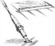
A very neat tail trimming gear is provided. In order to facilitate the work of trimming the tail it is necessary to have a low "gearing" between the operating wheel and the tail plane spar. But if the wheel has to be turned through more than one revolution for the complete range of tail settings, the difficulty arises that the pilot is uncertain as to the exact angle at which the tail is placed. To overcome this difficulty the designers of the "Starling" have produced a tail trimming wheel incorporating an epicyclic gear arrangement, so that although the wheel is turned through several revolutions, the pointer moves through a few degrees only.
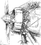
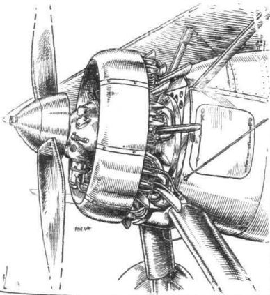
The Armstrong-Siddeley "Jaguar" fitted in the "Starling" is of the supercharged type for work at great altitudes, and is, needless to say, provided with the usual interrupter gear for the machine guns. A rather neat spinner has been produced, which takes the form of a truncated cone of plywood surrounding the airscrew boss. To the front of this is secured the small metal spinner which just leaves the claws for the Hucks starter free. It has been found that the plywood spinner stands up remarkably well, and its use avoids the annoying cracking which is, unfortunately, only too common with metal spinners.
We regret that the makers of the "Starling" do not wish any detailed weights to be published, nor actual performance figures. It may, however, be stated that the machine carries full service equipment in addition to over 50 gallons of petrol and 5 gallons of oil, and that with full load it is capable of a speed of 150 m.p.h. at 15,000 ft., while the ceiling is approximately 30,000 ft. The landing speed is in the neighbourhood of 50 m.p.h.
Описание:
- Flight, August 1928
THE ARMSTRONG WHITWORTH "STARLING - Flight, June 1929
BRITISH AIRCRAFT AT OLYMPIA
Фотографии

-
Air Enthusiast 1972-03 / Fighter A to Z (10)
Регистрационный номер: J8027 [8] Only one example of the Starling (J8027) was completed, development being abandoned in favour of the Starling II.
-

Flight 1928-08 / Flight
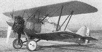
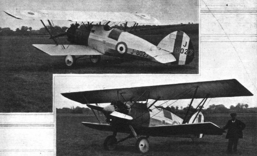
Регистрационный номер: J8027 [8] THE ARMSTRONG.WHITWORTH "STARLING": Three-quarter front and three-quarter rear views. The wing bracing is unusual in that both lift wires run to the front spar.
-

Aeroplane Monthly 1980-07 / R.Williams - Siskin Successor
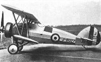
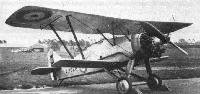
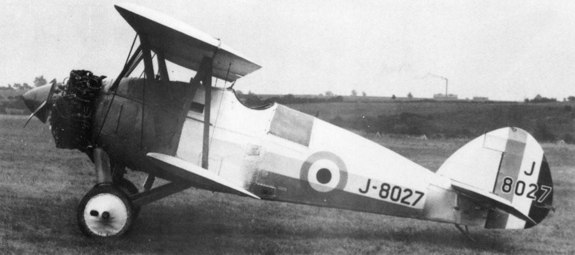
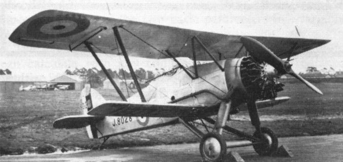
Регистрационный номер: J8027 [8] THE ARMSTRONG WHITWORTH "STARLING": Side View. Owing to the raised position of the pilot, the large angle of incidence of the top plane, and the absence of a cabane, the view is particularly good.
-
Flight 1929-07 / Flight
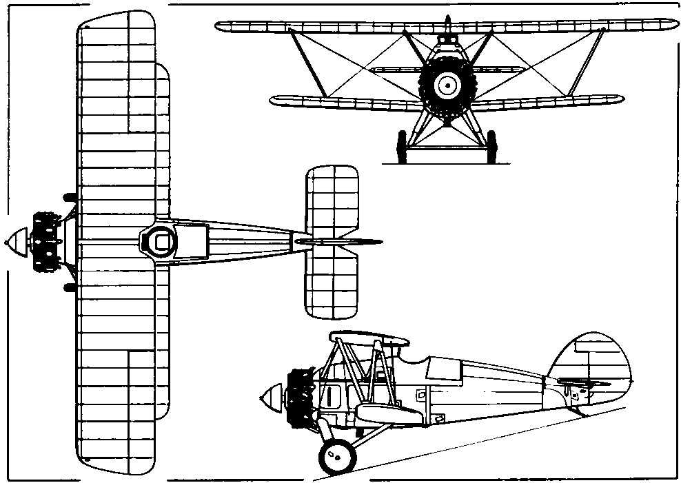
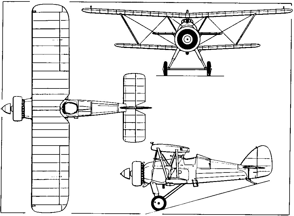
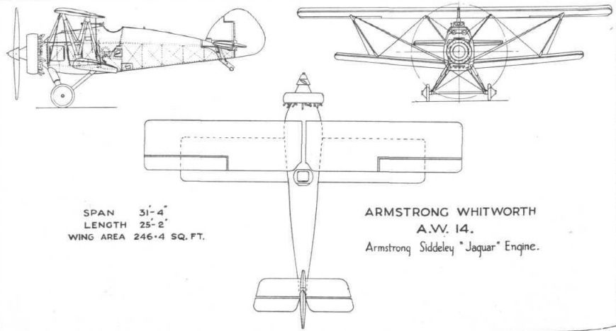
Регистрационный номер: J8027 [8] ARMSTRONG WHITWORTH "A.W. XIV" (Armstrong Siddeley "Jaguar").
-
Flight 1928-08 / Flight
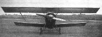
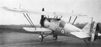
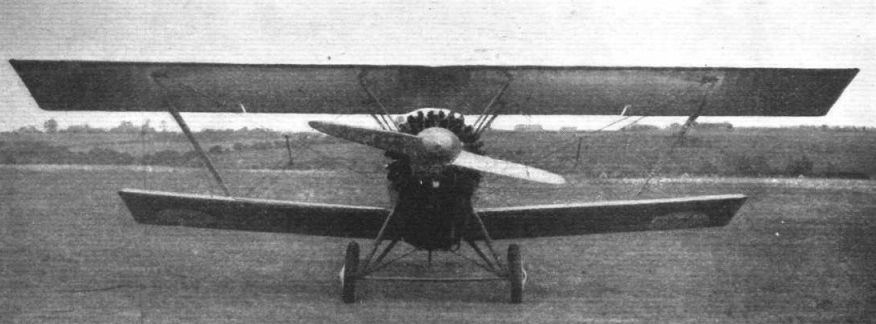
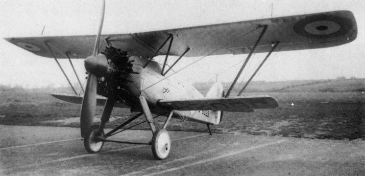
Регистрационный номер: J8027 [8] THE ARMSTRONG WHITWORTH "STARLING": Front View. Note the pronounced rake of the inter-plane struts. The engine is a supercharged Armstrong-Siddeley "Jaguar."
-
Aeroplane Monthly 1980-07 / R.Williams - Siskin Successor
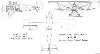
Регистрационный номер: J8027 [8] Armstrong-Whitworth Starling Single-Seater Fighter.
-

Aeroplane Monthly 1980-07 / R.Williams - Siskin Successor
Регистрационный номер: J8027 [8] The first Starling, J8027, which made its maiden flight on May 12, 1927. Its flying qualities left much to be desired.
-
Flight 1928-08 / Flight
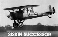
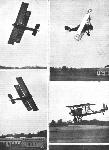
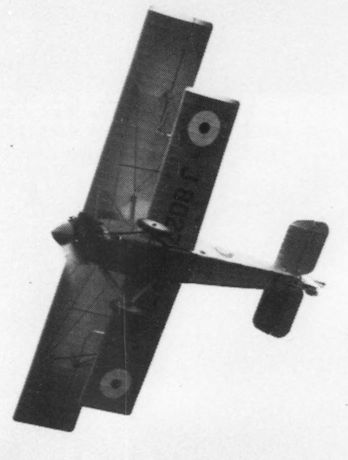
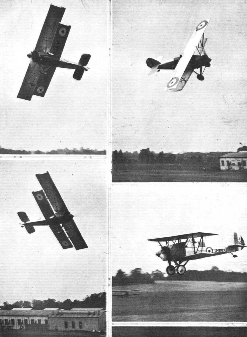
Регистрационный номер: J8027 [8] THE ARMSTRONG-WHITWORTH "STARLING" SINGLE-SEATER FIGHTER: The machine in various attitudes of flight, piloted by Mr. Campbell Orde.
-
Flight 1929-07 / Flight
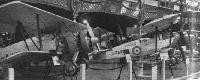
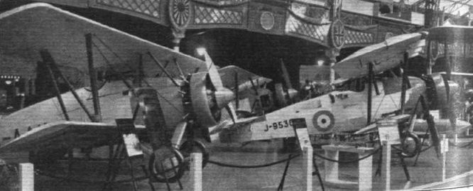
Some of the Armstrong Whitworth machines: On the left the A.W.14, on the right the "Atlas," and behind them the "Siskin." Note that all are fitted with the "Townend ring."
Другие самолёты на фотографии: Armstrong Whitworth Atlas / Ajax - Великобритания - 1925Armstrong Whitworth Siskin - Великобритания - 1921
-

Aeroplane Monthly 1980-07 / R.Williams - Siskin Successor
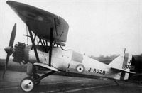
Регистрационный номер: J8028 [4] View of J8028, the Starling II, built to meet Specification F.9/26 and altogether more elegant than the first machine.
-
Air Enthusiast 1972-03 / Fighter A to Z (10)
Регистрационный номер: J8028 [4] The Starling II (J8028).
-
Aeroplane Monthly 1980-07 / R.Williams - Siskin Successor
Регистрационный номер: J8028 [4] -
Aeroplane Monthly 1980-07 / R.Williams - Siskin Successor
Регистрационный номер: J8028 [4] -
Aeroplane Monthly 1980-07 / R.Williams - Siskin Successor
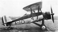
The second Starling II, A-I, a fleet fighter to Specification N.21/26
-
Aeroplane Monthly 1980-07 / R.Williams - Siskin Successor
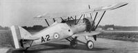
The final Starling, A-2, an interceptor fighter to F.20/27.
-
Flight 1928-08 / Flight
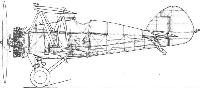
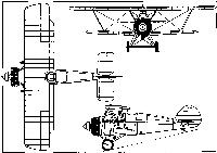
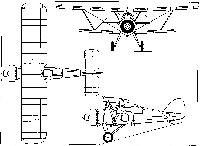
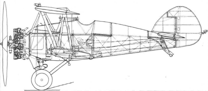
THE ARMSTRONG-WHITWORTH "STARLING": In order to avoid confusion it has been necessary to omit, in this side elevation, a good deal of the equipment, but sufficent detail has been retained to show the main structure. An unusual feature of the machine is that the wing section is a symmetrical one (R.A.F. 30). It should also be noted that the main lift wires both go to the front spar.
-
Flight 1929-07 / Flight
Among the firms who have done a lot of experimental work with the "Townend ring" is Sir W. G. Armstrong-Whitworth Aircraft, Ltd., whose A.W. XIV is shown
-
Flight 1928-08 / Flight
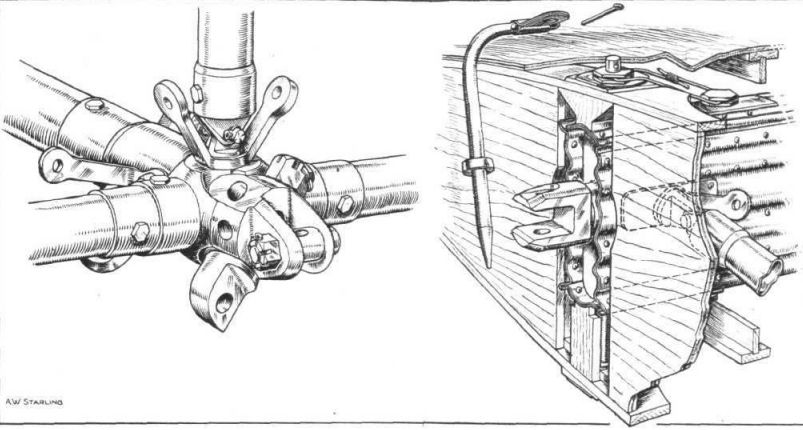
THE ARMSTRONG-WHITWORTH "STARLING": Sketches showing attachment of lower wing to fuselage, the fuselage joint being on the left and the wing root on the right.
-

Flight 1928-08 / Flight
The wing ribs of the Armstrong-Whitworth "Starling" are of wood. Their construction is indicated in this sketch, as well as the method of fastening them to the steel spars.
-
Flight 1928-08 / Flight
THE ARMSTRONG-WHITWORTH "STARLING": Use is made of an anti-vibration device which prevents the anti-lift wires from going slack. The inset shows a neat type of "skewer" used for the fastening of cowls, inspection doors, etc.
-
Flight 1928-08 / Flight
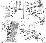
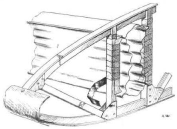
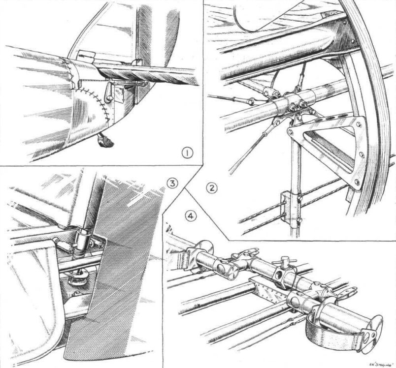
THE ARMSTRONG-WHITWORTH "STARLING": Some constructional details. (1) shows the stern of tne fuselage, with elevator controls, tail skid, etc. Details of the fuselage construction are shown in (2). The main structure is tubular, but fairings are added to this, which are in the form of channel section hoops carrying crinkled strip stringers. The trunnion arrangement of the tail for trimming is shown in (3), and the adjustable foot bar in (4). Pivoting in the central hexagonal fitting, the foot bar can be fixed in the position shown, or in the fully forward, or in a number of intermediate positions.
-
-
Air Enthusiast 1972-03 / Fighter A to Z (10)
The navalised version with engine Townend ring.
-
Flight 1928-08 / Flight
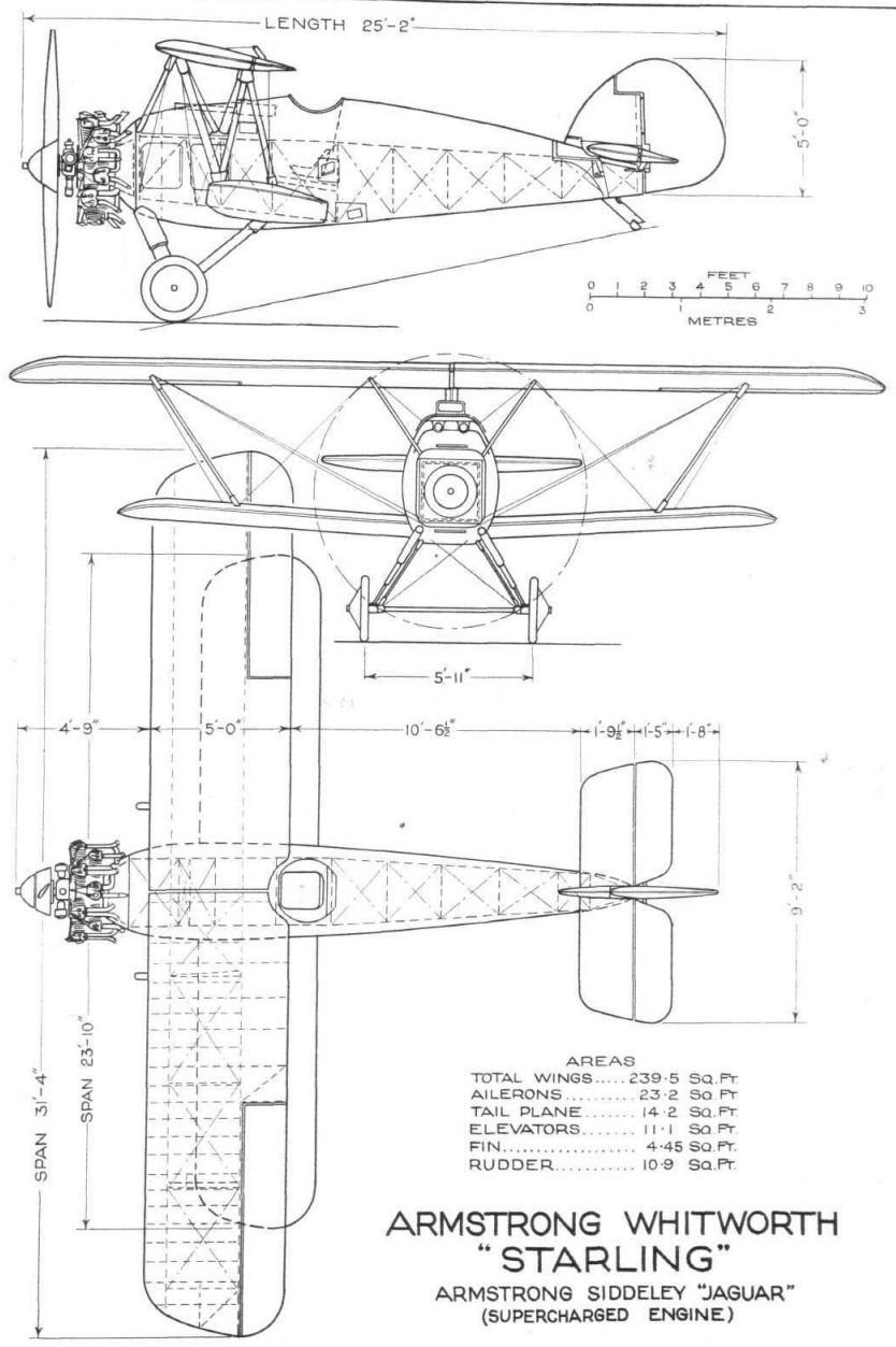
Armstrong Whitworth "Starling" Armstrong Siddeley "Jaguar" (Supercharged Engine)
-
Flight 1929-07 / Flight
Armstrong Whitworth A.W.14 Armstrong Siddeley "Jaguar" Engine


- Фотографии