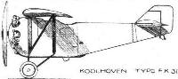
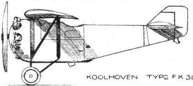
Koolhoven FK 31
В 1920 году Фредерик Кулховен покинул "British Aerial Transport Company", где спроектировал одноместный истребитель FK 23 Bantam, двухместный акробатический/гоночный FK 27 и четырехместный гражданский пассажирский FK 26. Ни один из этих самолетов не строился массово.
Вернувшись на родину в Голландию, Кулховен стал конструктором в учрежденной в 1922 году в Гааге фирме "Nationale Vliegtuigindustrie".
Первым самолетом, разработанным здесь, стал трехместный биплан Koolhoven FK 29 с мотором Bristol Lucifer мощностью 100 л. с. За ним последовал относительно удачный высокоплан FK 31, макет которого был представлен на в 1922 году на авиасалоне в Париже.
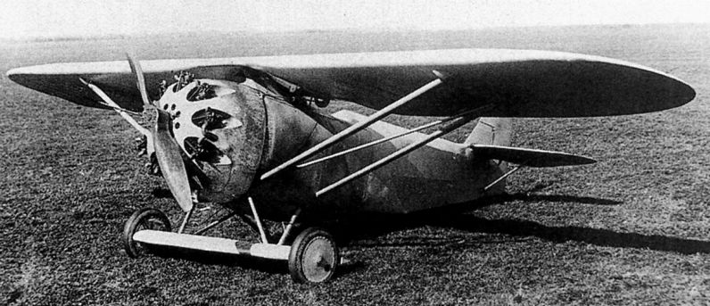
Первый прототип поднялся в воздух в 1931 году. Самолет отличали крыло с достаточно толстым профилем и объемистый фюзеляж круглого сечения. На втором, значительно улучшенном, прототипе стоял тщательно закапотированный мотор Jupiter и неубираемое шасси с независимыми основными опорами. Необычные стойки опоры-кабана соединяли фюзеляж опытной машины с крылом, на серийных самолетах крепление крыла к фюзеляжу было более традиционным.
В 1926 году Финляндия закупила восемь самолетов. Четыре FK 31 для войск в голландской Ост-Индии и четыре самолета, построенных по лицензии в Финляндии, получили доработанное горизонтальное оперение. Интерес проявили и во Франции, машина проходила испытания как De Monge М.101, но заказов так и не поступило.
ТАКТИКО-ТЕХНИЧЕСКИЕ ХАРАКТЕРИСТИКИ
Koolhoven FK 31
Тип: двухместный истребитель-разведчик
Силовая установка: один звездообразный мотор Bristol Jupiter IV мощностью 420 л. с.
Летные характеристики: макс. скорость 218 км/ч; практический потолок 7200 м; продолжительность полета 6 ч
Масса: пустого снаряженного 1040 кг; максимальная взлетная 1800 кг
Размеры: размах крыла 13,70 м; длина 7,80 м; высота 3,40 м; площадь крыла 27,20 м2
Вооружение: два неподвижных и два турельных 7,7-мм пулемета
Показать полностьюShow all
Flight, January 1923
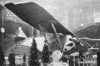
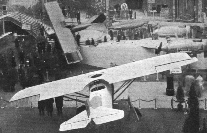
THE PARIS AERO SHOW 1922
F. KOOLHOVEN, ROTTERDAM
AFTER having been away from active participation in aircraft construction for several years, Mr. F. Koolhoven made his re-entry into aviation at the Paris Salon with a small parasol monoplane two-seater fighter, the "F.K.31." Having succeeded in forming a company in Holland, known as the N. V. Nationale Vliegtuig Industrie, of Rotterdam, one of the directors of which is Colonel Wallaardt Sacre, who built-up and was head of the Dutch Air Service, Mr. Koolhoven had but a few weeks in which to build his machine, and even then strikes in certain departments delayed matters considerably. Consequently, the finish of the "F.K.31" was not all that it might have been, but when one is told that the machine was built in three weeks, the lack of finish may easily be forgiven.
The "F.K.31," as already stated, is a parasol monoplane two-seater fighter, the chief object of the designer having been to obtain a good view and a free field of fire for both pilot and observer, as well as great manoeuvrability. The former has resulted in the choice of the parasol monoplane design, and the latter in a high-lift wing-section, giving a small overall size without unduly putting up the landing speed.
In the machine exhibited, the fuselage was of metal construction, while the wing was of wood. In future editions, however, we understand that probably the wing also will be of metal construction. The fuselage, which is of approximately rectangular section, although slightly rounded, is built-up of steel tubes, braced by tie-rods. From an external view, it might be concluded that the main fuselage structure is very deep. This is not, however, the case, as much of the depth is made up of light stringers and formers, placed outside the main framework.
The rear portion of the fuselage is covered with fabric, while in front the covering is in the form of aluminium sheet, the attachment of which to the fuselage structure is by a few bolts, the heads of which are of streamline shape and form handles. By undoing a few of these, the entire covering on both sides of the front portion can be removed, exposing the internal framework for inspection or overhaul. The operation of removing the covering occupies but a few minutes.
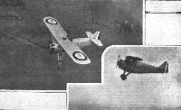
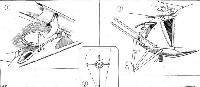
The pilot's cockpit is in front, and access to it is gained by removing a sliding panel on the side of the fuselage. A circular opening in the wing enables the pilot to look either over or under the plane, the central portion of which is thinned down for the purpose. Immediately behind the pilot's cockpit is that of the observer or gunner. This cockpit is divided into two separate compartments, one of which contains the gunner's seat, gun mounting, etc, while the other accommodates the wireless, photographic apparatus, etc. The gun mounting is unusual, and incorporates a sloping telescopic tube, with a spring which just balances the weight of the guns. By releasing a catch, the guns can be swung rapidly in any direction, elevated or depressed, and this with a minimum of exertion on the part of the gunner. As the trailing edge of the wing is cut away in the centre, the gunner obtains a particularly free field of vision, while he can also fire his gun in almost any direction. One of our photographs, taken from the gallery, gives a very good idea of this feature of the "F.K.31."
In the nose of the machine, enclosed in a circular cowl, is mounted the 400 h.p. Bristol "Jupiter" engine, on one of the swivelling mounts standardised for this engine. In the "F.K.31" there is no spinner, the engine cowling having been designed to avoid the extra complications. The cylinder heads project, through small openings in the cowl, and scoops are provided for the passage of air. The petrol tanks are mounted in the wing, so that direct gravity feed is obtained, simplifying considerably the petrol system and reducing the danger of fire by getting the tanks well away from the engine.
The wing, as already mentioned, is built-up of wood ribs on wood spars, but in subsequent machines probably the wing structure also will be made of steel. The wing section used is of the Schoukowsky type, with the maximum lower camber far back, and the centre of pressure also farther back than is usual in the more normal wing sections. The wing is braced on each side by a pair of struts, a diagonal strut serving to complete the structure. Except for the portion near the tips the wing is parallel throughout, and the horn balanced ailerons are remarkable for having a smaller chord at the tip than at the root.
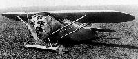
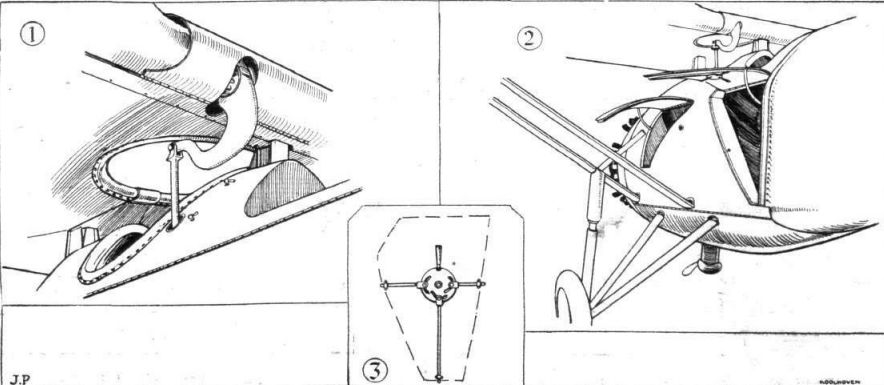
The undercarriage of the "F.K.31" is of unusual type, and somewhat reminds one of the Dornier machines. A small auxiliary plane is supported from the fuselage on two pairs of V-struts. These do not, however, run right out to the ends of the auxiliary plane, but are attached to it a couple of feet from the end. Inside the plane is a form of box spar, split vertically at the ends, into which the two short wheel axles are passed. The hinges occur at the point of attachment of the chassis struts to the spar. An unusual feature of the suspension is that the rubber shock-absorbers are wound around the ends of the spar, and that the axle, with its spool, is thus surrounded by the rubber cord. When the load comes on the wheel, the axle moves up against the rubber, which stretches, and in so doing, contracts the two halves of the split end of the box spar until the sides of the latter touch the axle spool. On the rebound the same occurs, the whole arrangement acting in the same manner as the Houdaille shock-absorber on an automobile. The wheel track is extremely wide, and the particular arrangement of the undercarriage chosen does not, Mr Koolhoven informs us, work out at all heavy.
The main characteristics of the "F.K.31" are as follows :- Length o.a., 7-2 ms. (23 ft. 7 ins.); span, 11 ms. (36 ft. 2 ins.); chord, 2-4 ms. (7 ft. 10 ins.); wing area, 27-5 sq. ms. (296 sq. ft.); weight, empty, 1,800 lbs.; military load, 1,500 lbs.; total loaded weight, 3,300 lbs. It should be noted that the military load is 45 per cent, of the total weight. Maximum speed at 1,000 ms., 255 kms. (158 miles) per hour; landing speed, 57 m.p.h.; service ceiling, 26,250 ft.; power loading, 8-25 lb./h.p.; wing loading, 11-15 lbs./sq. ft.
Показать полностьюShow all
Flight, December 1924
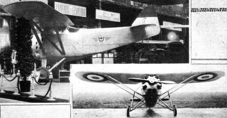
The Paris Aero Show 1924
THE KOOLHOVEN MONOPLANE
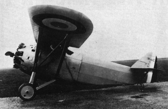
IT may be remembered that at the last Paris Aero Show the Nationale Vliegtuigindustrie of The Hague, Holland, otherwise the Dutch company of which Mr. Frederick Koolhoven is technical director and Lieut.-Col. H. Walaardt Sacre managing director, exhibited a monoplane with Bristol "Jupiter" engine. Since then the machine has undergone considerable development, and as now exhibited, the F.K.31 is certainly an exceptionally fine two-seater fighter. It is, as the accompanying photograph will show, a parasol monoplane, with strut bracing and an oleo undercarriage giving exceptionally long travel - 10 ins., to be exact. The engine fitted this year is a French-built Bristol "Jupiter."
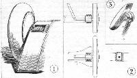
The F.K.31 has a steel tube fuselage structure, but whereas Fokker uses welding for joining struts to longerons Koolhoven has developed a special form of joint employing tubular rivets, no welding being used for stressed parts. The formers or bulkheads of the fuselage are made of Duralumin, a special paint being used to insulate the two so as to avoid any electric action. The rear portion of the fuselage is fabric covered, whereas the front part is covered with aluminium. Owing to the proximity of the fuselage deck fairing to the wing, entrance to the cockpits is gained by doors in the side, these forming the subject of one of our sketches. A special form of locking device has been evolved for the doors, by which the doors are kept quite light and yet are strong enough to form part of the fuselage structure. Three substantial rods or plungers are operated by a disc with eccentric slots, as shown in the sketch, and engage, when the door is closed, with the rest of the framework, one rod going to the bottom corner and the other two to the sides of the door.
Owing to the large cross-sectional area of the fuselage, there is unusually ample room in the cockpits, especially in the gunner's, who has plenty of room to move about in spite of the fact that his office is fitted out with three machine-guns, a large camera, wireless outfit, telegraphic as well as telephonic, ammunition, etc. The gunner's seat is mounted on a swivel, and can be instantly raised or lowered and swung to any position required. Two guns are mounted on a special support giving extremely free movement, and the third gun, used for firing downwards and aft under the tail, can quickly be swung out of the way and the camera brought into position above the opening in the floor.
The pilot, as is usual, operates two machine-guns, synchronized to fire through the propeller. In order to improve his view the monoplane wing is of thin section in the centre, and a circular opening is cut out between the spars, so that the pilot can see in practically all directions except straight down. It would be difficult to imagine a two-seater providing better view from both cockpits, while the equipment of the machine is such as to make the F.K.31 a formidable opponent. Included in it are a couple of pistols for firing Very lights, and as an instance of the thought that has been given to details, it may be mentioned that these pistols are permanently mounted in the fuselage and sighted in such a direction that the pilot or gunner cannot accidentally fire the lights into any part of the machine. The muzzles of the pistols project through small openings in the side, and the coloured lights are fired outward and downward. Dual controls are provided so that should the pilot be incapacitated the gunner can take control and bring the machine safely to earth.
The "Jupiter" engine is neatly cowled-in in so far as it is possible to enclose a radial air-cooled engine, and we noticed that Mr. Koolhoven had designed and fitted a special oil cooler projecting through the cowling under the engine.
In conclusion, it may be mentioned that the French rights have been secured by M. de Monge, who will build F.K.31's in France under licence.
<...>
Показать полностьюShow all