
Flight, October 1922
THE NEW DE HAVILLAND GLIDER
Parasol Monoplane with Wire Bracing
THE first of the two monoplane gliders which are being constructed at the Stag Lane works of the de Havilland Aircraft Co. will be finished this week, and it is hoped that some preliminary test flights may be made during the next week or so. On Monday we paid a visit to the D.H. works, and the glider was then erected and the bracing wires of the wings were being rigged and finishing touches given to various minor parts. At present the machine is fitted with a vee under-carriage, but probably later on, when the pilot has got used to the machine, a modified form, fitted inside the fuselage, will replace the present tubular vees so as to save resistance.
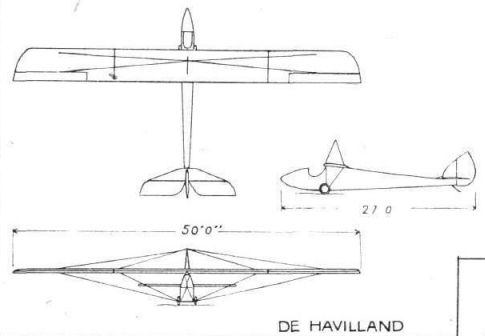
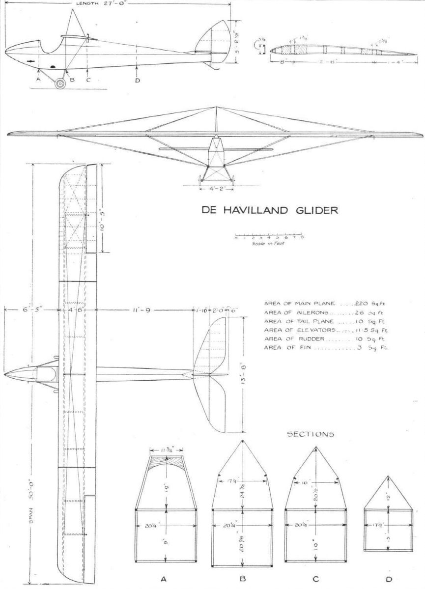
From the accompanying scale drawings it will be seen that the de Havilland glider is characterised by a parasol monoplane wing of very high aspect ratio (11 to 1), and that in spite of the fact that the wing has external wire bracing the appearance is very clean. The wing section used is R.A.F. 15, but a slight departure from the standard section has been made by stepping down slightly the ordinates of the top surface. This has been done in order to reduce spar weight, as it was found that with the spar section employed (I-section) the standard section would give rather too heavy spars. Both front and rear spars are of spruce, and the ribs are built up of spruce flanges, approximately 1/4 in. square, the form of which is preserved by webs or distance pieces tacked to one side of the spruce flanges, as shown in one of our sketches.
The internal bracing is in the form of small-gauge piano wire, and the use of wire strainers has been avoided by using U-bolts passing horizontally through the spars. The system of bracing is, however, different from that employed in the old Bleriots, inasmuch as alternate bays have the drag wires anchored to ordinary wiring plates. Thus the trueing-up is not quite the work of art it used to be in the Bleriots of old.
The monoplane wing is very simply mounted on the fuselage by two eye bolts engaging with corresponding forked end bolts at the apices of two formers or bulkheads rising up from the top longerons of the fuselage proper. The wing thus rests on the fuselage at two points only, and these on the centre line. The bracing is therefore relied upon to maintain the wing in its proper transverse position relatively to the fuselage.
As far as the stresses in the wing are concerned, the spars may be regarded as continuous beams, as the two end sections are not pin-jointed to the large-span centre section. Incidentally it may be mentioned that these joints in the spars occur at the point of contraflexure (i.e., where the bending moment is zero), so that no great strength is required in the joint.
The wing bracing is in the form of solid piano wire, all lift wires being duplicated, while the top wires are all single. The spars are braced at two points between the centre attachment and the tips, so that in spite of the large span the lengths of beam between supports are not great. The lift wires are attached to the under-carriage fitting on the lower longeron of the fuselage, and on the same fitting is a lug, projecting downwards and slightly to the rear, which is to serve as an attachment for the starting rope.
The covering of the wing is white cambric, doped with the new Cellon glider dope.
The anti-lift wires are attached to a fin or pylon mounted above the wing. Lateral control is by ailerons, and in connection with these it may be mentioned that the "differential" type, patented by the de Havilland Company, is used. With this arrangement the aileron which moves up travels through a greater angle than that moved through by the opposite aileron in travelling down. Experience with power-driven machines has proved this type of aileron control to be very efficient, and as ample control is a great advantage in a glider it has been used in preference to the ordinary type.
The fuselage, as regards its main portion, consists of four thin spruce longerons, joined by struts and covered with thin (1 mm.) three-ply wood. The struts run diagonally over the greater portion of the fuselage, but here and there, where local considerations demand it, the diagonal struts are reinforced by light bulkheads. It might be pointed out that these struts are merely butted on the longerons and not attached to them except via the ply-wood covering, the struts being intended to serve as stiffening pieces for the ply-wood rather than as bracing members, the ply-wood performing the function of bracing.
The fuselage proper is very shallow, and in order to bring it up to the wing an auxiliary structure, consisting of light formers, has been built on to its top. It might be objected that a lighter structure would have resulted from making the fuselage structure itself the required depth, but although in theory this would appear to be so, it was found in practice that to effect the necessary reduction in weight the longerons and ply-wood would have to be of such small dimensions that they would become impracticable. Consequently a shallow box was chosen for the stress-resisting part, and the rest was built on in the lightest form possible. The ridge along the top of the fuselage is formed by a wire running from the rear wing bulkhead to the tail plane, and fabric covering is put over the triangular section top thus formed.
The tail plane, elevators, fin and rudder are of very light construction indeed, and are covered, like the wings, with cambric. The elevator hinges are in the form of leather straps, similar to those used on draught screens, clotheshorses, etc., and provide quite the most light and efficient form of hinge possible. The angle through which the elevators can be moved is very great (i.e., 90° each way), and the gap left between tail plane and elevator spars is always kept closed. The tail plane is mounted on a small transverse bulkhead reaching some 5 ins. above the flat top of the fuselage proper, and is secured to it by two eye bolts. The rear spar of the tail plane is bolted to the fin post. Incidentally it may be pointed out that the curved leading edge of the tail plane is formed by several laminations of spruce, which form of construction is very strong and has the advantage that curved members can be formed without steaming.
The controls are of usual type, both the foot bar and the "joy-stick" being made from steel tube. The control cables pass to the tail on the outside of the fuselage, while those to the ailerons run up along the bulkhead behind the pilot, around pulleys, through the front portion of the wing and to the control cranks inside the wing. The pilot's cockpit is just in front of the leading edge of the wing, and here, as in the aft portion, the required depth of fuselage is provided by a light super-structure. The absence of "gadgets" in the cockpit makes one wish a similar simplicity were attainable in power-driven aircraft, where the pilot usually is so surrounded by instruments that one often wonders how he ever gets any time for piloting. The only instrument fitted at present is an air-speed indicator. This is one of the new instruments just put on the market by Smith and Sons, and is designed to give readings from 10 m.p.h. upwards. Also the "lag" has been reduced to a minimum, so that the instrument should be a valuable asset on a glider which has to be flown at practically a constant speed.
As already mentioned, the de Havilland glider is at present provided with a Vee under-carriage, but later a modified type, partly housed in the bottom of the fuselage, may be fitted. The present one has Vees of steel tube, with small scooter wheels carried on an axle slung on rubber cords from the bottom of the Vees. A tail skid built up of several laminations of wood is mounted on the downward extension of the fin post, and is anchored at its free end to a leather strap screwed to the lower longerons.
At the time of our visit to the de Havilland works the glider had not yet been weighed, but it was expected that the weight empty would be in the neighbourhood of 250 lbs., in which case the loaded weight will be approximately 400 lbs., or a wing loading of under 2 lbs./sq. ft.
The machine is finished in black and white, the wings and tail being left the original colour of the fabric, while the fuselage and under-carriage are black. At the moment the glider has not been entered for the Daily Mail competition, but we hope it will be entered before the closing date, October 7.
- Flight, October 1922
THE NEW DE HAVILLAND GLIDER
Фотографии
-

Flight 1922-10 / Flight
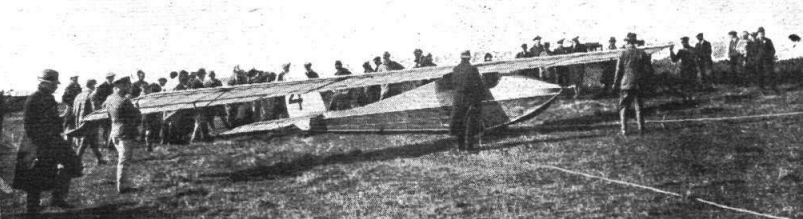
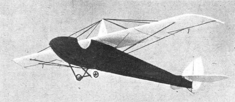
The De Havilland Glider "Sibylla" ready for a flight.
-
Aeroplane Monthly 1982-05 / P.Capon - Stag Lane /Capon's Corner/
The D.H.52 glider at Stag Lane in October 1922. Note strutted undercarriage which was not fitted when it took part in the Itford gliding competitions later that month.
-

Aeroplane Monthly 1998-10 / R.Riding - A Broad experience (1)
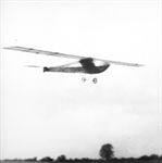
Photographed immediately after being bungee-launched is one of the two D.H.52 gliders built for the 1922 Daily Mail £1,000 Gliding Competition held at Itford, Sussex. Broad flew one, E.D.C Herne flew (and crashed in) the other.
-

Flight 1922-10 / Flight
Capt. Broad on the De Havilland Glider No.4 making a flight from Beddingham Hill.
-

Flight 1934-12 / Flight
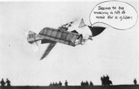
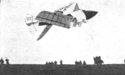
"The wings became self-warping, and I held the camera to my eye, waiting, waiting... until at last they gave up the ghost."
-
-

Flight 1922-10 / Flight
THE DE HAVILLAND GLIDER: Photograph taken from below of a scale model of the machine.
-

Flight 1922-10 / Flight
SOME CONSTRUCTIONAL DETAILS OF THE DE HAVILLAND GLIDER: 1. Front portion of the fuselage and the Vee undercarriage. 2. The bulkheads or formers to the apices of which the wing is attached. 3. Details of the top of the rear bulkhead, showing attachment of the wire which forms the ridge of the triangular top of the fuselage. 4 shows construction of superstructure over pilot's cockpit, and 5 some of the smaller details. In 6 is shown one complete elevator flap, with trailing edge cut through to show laminated construction. The leather elevator hinges are indicated in 7, and in 8 is seen the U-bolts and compression struts of the internal wing bracing. 9 shows the bulkhead on which the front edge of the tail plane is mounted.
-

Flight 1922-10 / Flight
De Havilland
-

Flight 1922-10 / Flight
De Havilland Glider


- Фотографии