

Варианты
- Caspar - U.1 - 1922 - Германия
- Yokosuka - 1-Go - 1927 - Япония
Flight, June 1923
THE CASPAR SPORT SEAPLANE
60 H.P. Siemens Engine
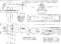
AMONG the modern German aircraft passed by the Commission of Guarantees as conforming to the regulations restricting horse-power, etc., of commercial machines is a very interesting little two-seater seaplane designed by Herr Heinkel and built by the Caspar Werke of Trawemunde. Compactness and ease of erecting and dismantling are the predominant features aimed at, and it is rumoured that the machine may be used from a large submarine. In fact, the United States Government has purchased one of these machines with, it is stated, the intention of testing the suitability of the Caspar U1 for this purpose. This fact may explain the reason for so designing the machine that it will, as indicated in the accompanying diagrams, pack into a cylindrical case measuring 24 ft. 4 ins. in length by 5 ft. 7 ins. diameter.
Compactness and ease of dismantling being the chief considerations, the Caspar U1 was made a biplane, the monoplane wing of the same area being too large for the purpose, and in order to facilitate removing and erecting the wings these were made cantilever surfaces. In the case of the bottom plane this arrangement is probably quite satisfactory, but we confess we have certain misgivings concerning the top plane.
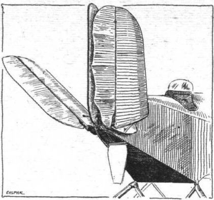
From the front elevation of the machine it will be seen that the width of the excrescence on the fuselage, which carries the top plane, is relatively narrow - about 18 ins., and the soundness of attaching to such a narrow structure the upper, and more heavily stressed, wing of a biplane may be questioned. It is not so much a matter of pure bending stresses, although these will probably be serious enough, as of torsion and rocking of the wing. To make matters worse, the ailerons are fitted to the top plane, so that the loads tending to twist and rock the wing may be assumed to be increased. By using an excess of material it is, of course, possible to provide the necessary strength, but at the expense of a good deal of weight. We should have thought that it would have been preferable to use a pair of lift struts on each side, but probably this would have meant a departure from the ideal which the designer had set himself, and certainly it would have meant extra fastenings to undo when dismantling the machine. It may be that the present arrangement, entailing a somewhat greater weight, was chosen deliberately in order to retain the extraordinary simplicity of the wing attachments.
Facility of erecting and dismantling has been carried to such perfection that no tool of any sort is required for these operations. The wings are locked in place by the movement of a single lever projecting from the fuselage, the movement securing both wings at once. For removing the wings the lever is moved in the opposite direction, when the top plane can be lifted off and the lower plane withdrawn by sliding it out of its notch in the bottom of the fuselage. The aileron controls must, of course, be broken and joined up again, but the fittings used are such as to require no tools.
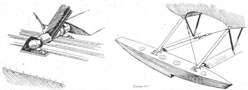
The two floats, which are of the single-step type with flat bottom ahead of the step and V-bottom aft of it, are of sufficient length to avoid the use of a tail float. They are mounted on steel tube struts, and the attachments are such as to avoid the use of tools. The fittings on the floats and fuselage are in the form of steel hooks pointing away from one another. When, therefore, the diagonal cable on each side is slacked off, by means of a quick-release, the strut ends can slide out of the hooks and float and struts removed from the fuselage. Laterally the float struts are so triangulated as to form a letter M, with the float cross-tubes joining the lower ends of the limbs.
The fuselage is built of wood, and covered with three-ply. The excrescence carrying the top plane contains the petrol tank, so that direct gravity feed to the carburettor can be employed, thus simplifying the petrol system. The pilot's cockpit is immediately aft of the top plane, and as the wings are fairly heavily staggered he obtains an excellent view.
The vertical fin is built integral with the fuselage, and the rudder, tail plane, and elevators are built up of steel tubing and fabric covered. In order to save stowage space, the two halves of the tail plane are hinged on their upper surface, near the sides of the fuselage, and by removing a pin they can be folded up against the fin.
A Siemens five-cylinder radial air-cooled engine is mounted in the. nose, and neatly cowled-in, with the cylinder heads projecting. The propeller is secured by a sort of bayonet joint, a 90° turn unlocking the propeller boss from its hub Again no tool is required. Petrol sufficient for a two-hours' flight at full throttle is carried, giving a range of approximately 180 miles.
It is stated that a crew of four men can erect the machine in 1 min. 5 secs., and dismantle it in 1 min.
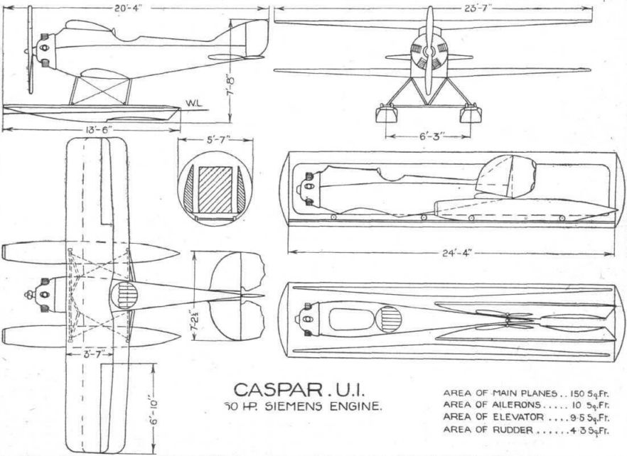
Following are the main characteristics of the Caspar U1: Length, o.a., 6-2 ms. (20 ft. 4 ins.); span, 7-2 ms. (23 ft. 7 ins.); chord, 1-1 m. (3 ft. 7 ins.); wing area, 14 sq. ms. (150 sq. ft.); length of floats, 4-1 ms. (13 ft. 6 ins.); volume of floats, 430 litres (approximately 15 cubic ft.); weight of floats, 26 kgs. (57 lbs.); spacing of floats, 1 -9 m. (6 ft. 3 ins.) over centre lines: Weight of machine empty, 360 kgs. (790 lbs.). Useful load, 150 kgs. (330 lbs.). Total loaded weight, 510 kgs. (1,120 lbs.). Wing loading, 7-46 lbs./sq. ft. Power loading, 18-7 lbs./h.p. Maximum speed, 145 kms. (90m.p.h.). Cruising speed, 75 m.p.h. Landing speed, 75 kms. (47 miles) per hour. Climb to 1,000 ms. (3,280 ft.) in 7 mins.
Описание:
- Flight, June 1923
THE CASPAR SPORT SEAPLANE - Flight, August 1923
GOTHENBURG International Aero Exhibition 1923
Фотографии
-
Flight 1923-06 / Flight
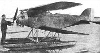
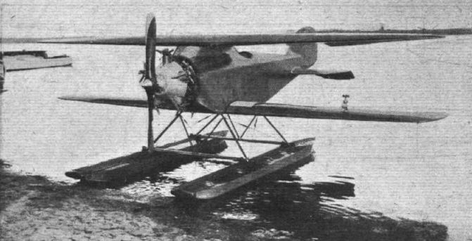
The Caspar seaplane: three-quarter front view.
-

Flight 1923-08 / Flight
The Caspar U.I cantilever biplane: This machine can be dismantled, without using a single tool, by four men in 1 min. 10 secs. The engine is mounted on a swivelling mount, somewhat after the fashion patented by Boulton and Paul, Ltd.
-
Flight 1923-06 / Flight
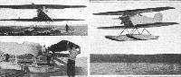
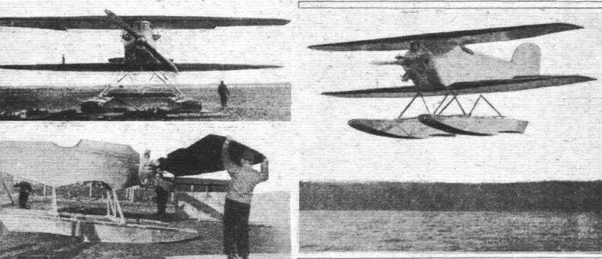
THE CASPAR SEAPLANE: On the right, the machine in flight. On the left, front view; and, below, dismantling the wings.
-
Flight 1923-06 / Flight
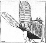
THE CASPAR SEAPLANE: Sketch showing how tail is folded.
-
Flight 1923-08 / Flight
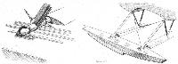
THE CASPAR SEAPLANE: Details of float attachment.
-
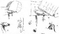
Flight 1923-08 / Flight
THE CASPAR TYPE U.l SEAPLANE: Some constructional details. The whole of the machine can be dismantled without the use of tools. Our sketches show the details of the folding tail plane. When a trap door in the bottom of the fuselage is opened the lever A can be pulled down, and thereby releases the bayonet joint BC. The tail is then free to be swung upwards, as the elevator tube has a universal joint at E. Short pegs or dowels, D, take the shear at leading and trailing edges when the tail is spread.
-
Flight 1923-06 / Flight
Caspar U.1. 50 hp Siemens Engine

- Фотографии