
Варианты
- Vickers - Viget - 1923 - Великобритания
- Vickers - Vagabond - 1924 - Великобритания
Flight, August 1923
THE VICKERS "VIGET" LIGHT 'PLANE
750 c.c. Douglas Engine
AN exceptionally fine piece of work. This is the main impression left upon one's memory after a thorough inspection of the new Vickers light 'plane, designed and built for the forthcoming competitions at Lympne in October. The machine is in no way original, and for that matter might equally well have been built in 1913. The "Viget," as the type has been christened, is in fact a perfectly normal equal-span, non-staggered biplane, with Rafwire bracing and one pair of interplane struts. The construction throughout is of the normal wire-braced form used in larger machines, and aerodynamically the "Viget" is equally orthodox. This fact should not, however, be used as a criticism of the design. While there are those who believe that the monoplane offers the only solution of really low-power flight, there are others who maintain that this has not yet been proved, and that there is at least a possibility that the braced biplane, with its lighter construction and smaller overall size, offers Certain advantages which may outweigh any small aerodynamic advantages which the cantilever monoplane possesses. Mr. Rex Pierson, Vickers' chief designer, has gone into the question very thoroughly, and the fact that he has decided in favour of the biplane appears to prove that he has come to the conclusion that, by the time all the factors have been taken into consideration, the biplane offers the better solution. For several reasons we are pleased that Mr. Pierson should have come to this decision. If we are to learn anything from the competitions (and we are not very hopeful in this respect) it is essential that as many different types as possible should be represented, so that they can be compared and their performances and behaviour noted. Especially when, as in this case, the engine of the biplane is the same as that used on some of the monoplanes is comparison facilitated, and there is thus more likelihood of finding out definitely whether in fact any one type does possess any very pronounced advantage over any other type. Personally we are inclined to think that there is so little to choose between the monoplane and the biplane that in the future there will be room for both.
The Vickers "Viget," then, is a perfectly orthodox biplane, using normal bracing and having R.A.F. 15 wing section. The machine is well illustrated in the accompanying photographs, general arrangement drawings and perspective sketches. What is more difficult to show, however, is the excellent workmanship and careful detail design put into the machine, and in this respect the "Viget" might have been built for an aero show, the work being well up to any show finish usually found on larger aircraft. It appears that Vickers have, in building this machine, worked on the old assumption that what is worth doing at all is worth doing well. Certainly both workmanship and finish are as good as on the larger aircraft carrying the Vickers name.
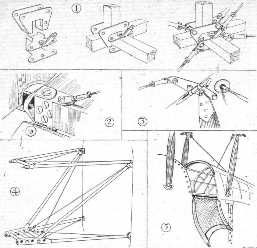
The fuselage of the "Viget" is a wire-braced girder structure with spruce longerons and struts. The longerons are of plain square section, while the struts have been spindled out to a cruciform section. The fuselage fittings are of a novel type, and appear especially suitable for light 'planes, where the longerons are of such small size as to render piercing out of the question. The fittings on the "Viget" are of Vickers Duralumin, and are so designed as to wrap around the longerons, small woodscrews being used for locating the fittings on the longerons. The fittings are formed of two separate units, one for the vertical and one for the horizontal bracing. The horizontal portion is slipped into a cut-out in the vertical component, as indicated in one of our sketches, so that it becomes necessary to slide the fittings on to the longerons. It might be objected that it is thus impossible to replace a damaged fitting without dismantling the fuselage. While this is admittedly so, it is possible to meet the criticism by pointing out that a fitting should not need renewal, and that if the fuselage is accidentally damaged the longerons are likely to need replacing, in which case dismantling would, be necessary anyway.
In section the fuselage is rectangular as regards its main structure, but a shallow fairing has been wadded to the bottom and a much deeper one to the top, which latter serves to streamline the pilot's head and shoulders. The sides of the fuselage are flat.
The pilot's cockpit is under the trailing edge of the top plane, as the machine is a vertical biplane, and in order to facilitate entrance a small door is provided on the port side. As the main structure of the fuselage is not very deep, while the deck fairing is of considerable height, this door enables the pilot to step into the cockpit without great difficulty. The controls are of usual type, the joy-stick being a Duralumin tube mounted on a universal joint. A complete set of instruments is carried, comprising air-speed indicator, revs, indicator, altimeter and inclinometer.
The 750 c.c. Douglas fiat twin air-cooled engine is mounted in the nose of the fuselage, and is neatly cowled in. Immediately aft of the engine housing is a fireproof bulkhead, and from this the lower longerons are extended forward in the shape of two steel tubes. The top longerons of this portion are also tubes, but slope down at a sharp angle to meet the lower longerons. The forward ends of the steel tube structure thus formed are joined by cross tubes carrying the engine. Contained in an aluminium casing, whose feet rest on the top of the engine crank-case, is a large sprocket carried on the propeller shaft, which latter rests in bearings in the casing and is provided with a ball thrust bearing. The drive is by chain, and the size of sprockets is such as to give a reduction gearing of 2 1/2 to 1. The casing containing the propeller shaft and sprocket is braced at the top in a fore and aft direction by tubes from the engine bulkhead.
As the propeller shaft is mounted above the engine, the latter is placed sufficiently low to allow of direct gravity feed from the tank mounted in the deck fairing behind the engine bulkhead. Thus no petrol pumps are necessary, and the whole petrol system is simplified.
The undercarriage is of normal V-type, built up of streamline steel tubes, and rubber cord shock absorbers are used.
Constructionally the wings are of standard type, of wood construction and fabric covered. The wing section used is the R.A.F.15, and the biplane structure is only unusual in that the ailerons are of very large area and run right across. The top ailerons are hinged to the top corner of the upper, rear wing spar, while the lower ailerons are hinged at the bottom corner. Inter-plane aileron wires connect upper and lower ailerons, and when these have been cast adrift the top ailerons can be folded upwards and the lower ailerons downwards. The wings are hinged at the rear spar, and when folded back, with the aileron flaps up and down respectively, lie back with their rear spars against the sides of the fuselage. Thus the folded width comes within that stipulated for the transport test of the competitions at Lympne (7 ft. 6 ins.). When the wings are folded one man can quite easily wheel the machine along a level road, although a steep hill might prove somewhat beyond the strength of the average pilot. The bottom rear spar is hinged to the forked ends of a tube running across the bottom of the fuselage, and the L-bolts in the front spar, by means of which the wings are locked in position when spread, are fitted with catches similar to those commonly found on umbrellas. A small tool in the form of a short tube is slipped over the end of the bolt and over the wire catch, depressing the latter so as to allow the bolt to be withdrawn. This forms the subject of one of our sketches.
The tail of the Vickers "Viget" is of standard type, externally braced by streamline wires. Provision is made for adjustment of the tail plane while the machine is on the ground. This adjustment is of very simple type but provides for quite a wide range of angles. The stern post of the fuselage is in the form of a steel tube. Around this tube is wrapped a piece of sheet steel open at the side facing the rear spar of the tail plane. In the edges, which are shaped to the radius of the rear spar around the front spar as centre, a series of holes are drilled corresponding with holes in a steel fitting on the rear spar of the tail plane. The holes in the two members of the fitting are so staggered in relation to each other that a movement up or down corresponding to but a fraction of the diameter of the holes brings two sets of holes opposite one another. Thus a very fine adjustment is possible.
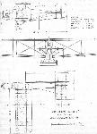
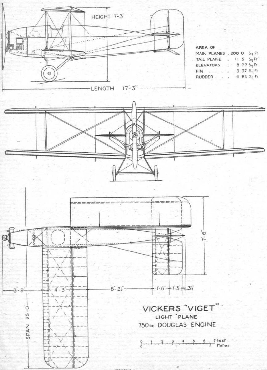
Our general arrangement drawings show the main dimensions of the Vickers "Viget." Suffice it to add that the estimated total loaded weight was 625 lbs., but that the machine has come out somewhat lighter than that figure, so that with a pilot of 168 lbs. and 1 gallon of petrol and 1/2 gallon of oil the machine will probably weigh slightly under 600 lbs., giving a wing loading of just under 3 lbs./sq. ft. If we assume that the Douglas engine will develop about 20 h.p. at the speed at which it will be run for normal flying (as distinct from the conditions in the "economy" competition) the power loading becomes approximately 30 lbs./h.p.
- Flight, August 1923
THE VICKERS "VIGET" LIGHT 'PLANE
Фотографии
-

Aeroplane Monthly 1985-02 / R.Riding - Vickers Viget /British pre-war ultralights/ (47)
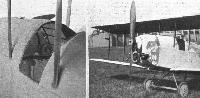
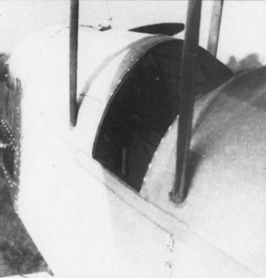
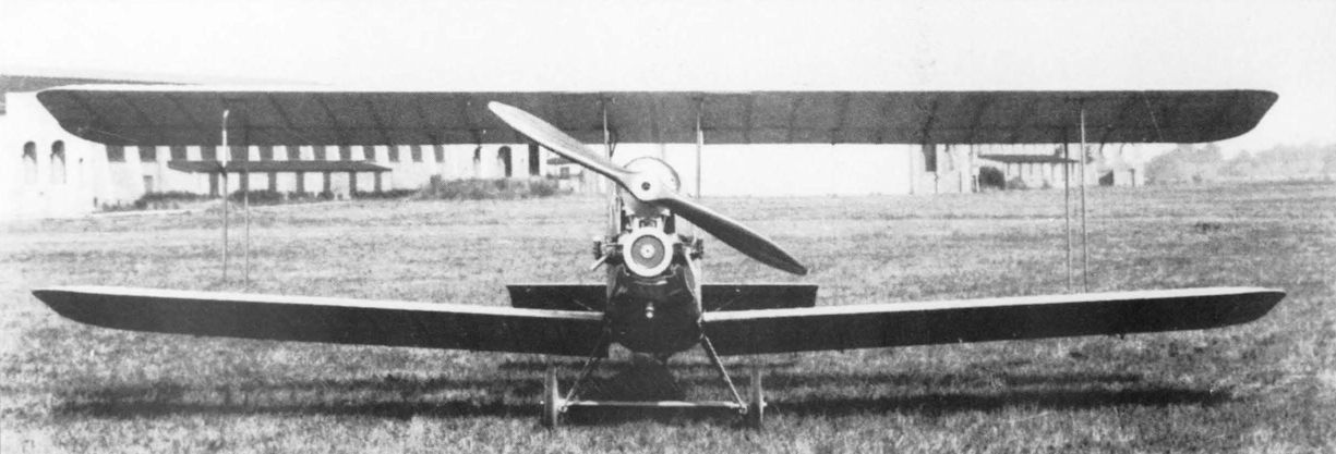
The prominent 2 1/2:1 chain reduction gear can be seen. The low position of the engine allowed direct gravity fuel feed from the tank, which was situated under the deck fairing just aft of the engine bulkhead.
-
Flight 1923-09 / Flight
THE VICKERS "VIGET": On the left, a view into the cockpit, and, on the right, the mounting of the Douglas engine. Note the chain reduction gear.
-
Aeroplane Monthly 1985-02 / R.Riding - Vickers Viget /British pre-war ultralights/ (47)
The Viget's cockpit was tiny and the instrumentation minimal.
-

Aeroplane Monthly 1985-02 / R.Riding - Vickers Viget /British pre-war ultralights/ (47)
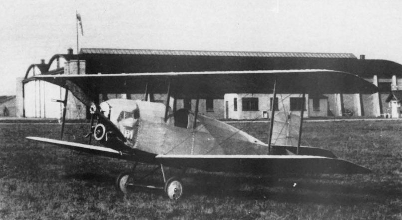
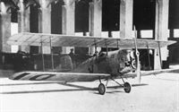
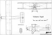
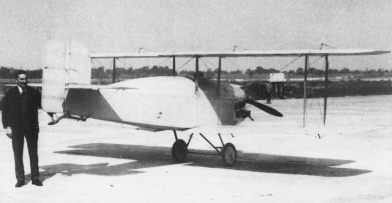
One of three views of the pristine Viget taken at Brooklands shortly after the machine was completed during the summer of 1923. The Viget was in every respect a miniature light aeroplane, beautifully built and finished in true Vickers fashion. Only the bottom wing had dihedral and the wings were unstaggered.
-

Aeroplane Monthly 1985-02 / R.Riding - Vickers Viget /British pre-war ultralights/ (47)
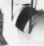
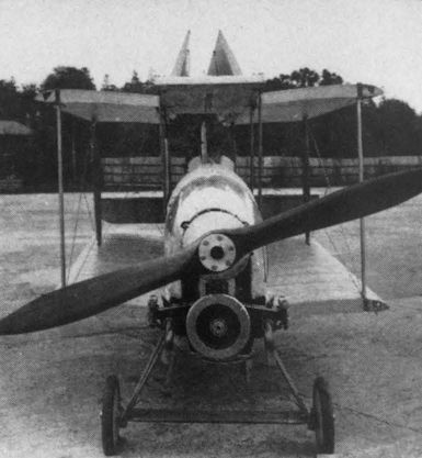
The width of the Viget with wings folded was 7ft 6in.
-

Aeroplane Monthly 1985-02 / R.Riding - Vickers Viget /British pre-war ultralights/ (47)
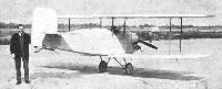
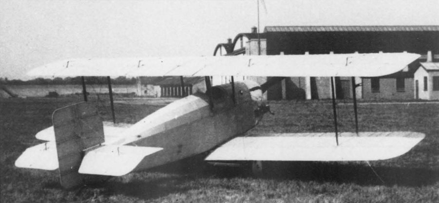
The three-quarter rear view at right emphasises the full-span ailerons and compact appearance.
-

-
Flight 1923-09 / Flight
THE VICKERS "VIGET" LIGHT 'PLANE: This photograph gives a good idea of the ease with which this machine can be wheeled along by one man. For transport over longer distances the wings are folded.
-

Aeroplane Monthly 1985-02 / R.Riding - Vickers Viget /British pre-war ultralights/ (47)
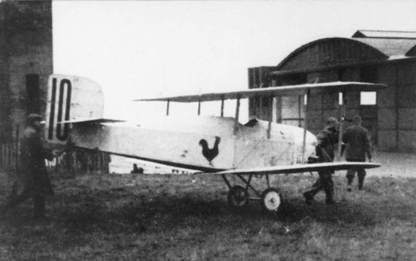
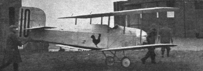
View of the Viget at the Lympne meeting in October 1923. The aircraft is unregistered, has the competition number 10 on the rudder and the pilot s personal logo painted on the fuselage sides!
-

Flight 1923-10 / Flight
The Vickers "Viget" at Lympne: Wheeling the machine out for a flight. Note the pilot's name painted on the side of the fuselage.
-
Aeroplane Monthly 1985-02 / R.Riding - Vickers Viget /British pre-war ultralights/ (47)
View of the Viget at the Lympne meeting in October 1923. The aircraft is unregistered, has the competition number 10 on the rudder and the pilot s personal logo painted on the fuselage sides!
-
Aeroplane Monthly 1985-02 / R.Riding - Vickers Viget /British pre-war ultralights/ (47)
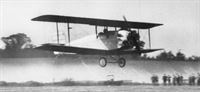
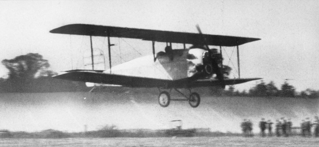
THE VICKERS "VIGET": The machine is coming in after her first flight, piloted by Capt. Cockerell.
Photograph was taken at Brooklands during the summer of 1923 and shows Cockerell flying the Viget during an early test flight. -
Flight 1923-11 / Flight
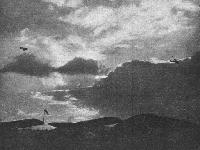
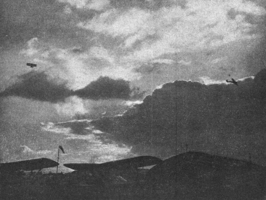
LIGHT 'PLANES AT HENDON: 3. Cockerell "power-soaring" on the Vickers "Viget" biplane (Douglas engine).
-
Flight 1923-10 / Flight
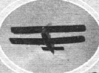
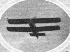
Capt. Cockerell on the Vickers "Viget" (No. 10) flying above one of the A.N.E.C. monoplanes (No. 17) at Lympne.
Другие самолёты на фотографии: ANEC I / II - Великобритания - 1923
-
Flight 1923-11 / Flight
EVENING AT CROYDON DEMONSTRATION: On the left, in the air, is seen the Vickers "Viget" light aeroplane and on the right the Avro light monoplane.
Другие самолёты на фотографии: Avro Type 560 - Великобритания - 1923
-

Flight 1923-09 / Flight
THE VICKERS "VIGET" LIGHT 'PLANE: Some constructional details - 1. Analytical sketches of the fuselage fittings, which are made from Duralumin. 2. Sketch showing hinge on lower rear spar. 3. Locking pin with "umbrella" catch on top front spar. A small tube is used for slipping over the end of the pin, compressing the catch so that it will allow the pin to be withdrawn. 4. Diagrammatic perspective view of the tubular engine mounting. The upper tubes brace the top of the sprocket casing, while the engine is supported on the two front transverse tubes at the bottom. 5. Access to the pilot's cockpit is facilitated by a door in the coaming.
-
Flight 1923-09 / Flight
Vickers "Viget" Light 'Plane 750cc Douglas Engine
-


- Фотографии