
Flight, May 1929
THE VERVILLE "AIR COACH”
An American Cabin Monoplane
WE give below a brief description, together with illustrations, of a commercial machine produced by the Verville Aircraft Co., of Detroit, Mich., and which was recently flight-tested at the Ford Airport, by William S. Brock. The Verville "Air Coach" as it is called, was designed by Mr. Alfred V. Verville - secretary and chief engineer of the company - who is an aeronautical engineer of some years' standing, having been responsible for the design of several successful machines, amongst which may be mentioned the pursuit 'planes V.C.P.-1 and P.V.-1, the Verville-Sperry "Messenger," the Verville-Packard racer (1920 Pulitzer winner), the Verville-Sperry (1924 Pulitzer winner), the Buhl "Airster," etc.
The "Air Coach" is a 4-seater high-wing "semi-cantilever" monoplane, similar in general appearance to other machines of this type, but possessing several original constructional features. The most important of these is perhaps the fuselage structure, which eliminates the inter-section of fuselage truss tubes intersecting the side windows and so providing a range of vision entirely free from obstructions. Unfortunately, details of this fuselage construction (a patent on which has already been applied for) are not at the moment available, but it will be apparent from our illustrations that whatever it is, an exceptionally neat job results.
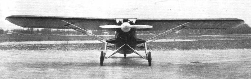
Another unusual feature is in the method of attaching the wing-brace and chassis struts on the fuselage. Two short streamline sponsons, or stubs, semi-elliptical in plan form, and 16-in. in length, project horizontally from the lower longeron in the 'plane of the front spars. To these the forward wing brace struts and chassis oleo struts are attached. By attaching the wing struts in this manner parasite resistance is reduced, as compared with the conventional type of exposed strut bracing now in vogue. The landing gear shock struts are attached at the outer extremity of the stubs, allowing a 7-ft. chassis wheel tread. The stubs or fins, as they might be called, also serve as small compartments 8-in. deep, with hinge doors on their top side. The left compartment will be used for the lighting battery, and the other for tools; thereby making possibility of more room in the already spacious cabin.
Other items distinctive in the Verville "Air Coach" include a rudder streamlined into the fuselage, and an especially designed selective and service hand brake control, allowing for easy braking of either wheel alone, or the locking of both wheels. A tail wheel equipped with full caster aerol shocks and built into the fuselage is provided to decrease drag and for simplicity and sturdiness of construction.
With his wide experience in the designing of racing and pursuit aircraft, Mr. Verville has succeeded in combining many speed producing characteristics of these types with the convenience and comfort of the modern automobile sedan.
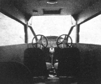
The cabin of the "Air-Coach," in size, lines and appointments, is closely analogous to those of the modern auto body. It is completely equipped to satisfy the purpose for which the ship was built. It has a minimum length of 8 ft. and maximum length of 10 ft., the after 2 ft. being used for storage purposes. Height of the cabin is 4 ft., or the same as the average automobile sedan. Also there is an average width of 39 in. Displacement capacity in the cabin is figured at 126 cub. ft. Control wheels are mounted on upright columns, designed to make easily possible either dual or single control. The control columns are of the torque drive shaft type, with a spline connection at their base. For purposes of safety and convenience either column may be disengaged by unscrewing a knurled nut. Either column may be removed without disturbing the functioning of the controls proper.
Between the two forward seats is the braking lever. To brake the left wheel the lever is pulled to the left, exactly like the operation of a joy stick. The reverse, of course, is true when the opposite brake is applied. To apply both brakes simultaneously, and for locking the wheels, it is only necessary to press on the ball and pull the lever straight back.
Standard equipment on the dash includes a turn and bank indicator, climb indicator, compass, air speed indicator, oil pressure gauge, oil temperature gauge, altimeter, clock, instrument lights, and all light switches, and a Scintilla magneto switch. Except for the magneto switch, all the plane's instruments are Pioneer, and nicely centred on a 27 in. by 9 in. crackle varnished dural board. The throttle is of the push and pull type.
As previously stated, the cabin has a large expanse of unobstructed vision, both on the front and sides. Pittsburgh shatter-proof "Duplate" glass is seated into the windows by a method similar to that used in automobile body construction. The side windows slide back and forth, easily converting the plane into an open job. Two doors, also fashioned after those of the automobile, are located abreast of one another aft of the two rear seats, allowing easy ingress or egress. Two large skylights, fitted with green pyralin, are set in tandem in the cabin roof, between which is the cabin's electric light. On the back wall of the cabin is a door, 18 in. by 12 in. in dimension, and equipped with Cinch fasteners for inspection of the tail's interior.
The four seats in the cabin are bolted to the tubular structure of the fuselage. All upholstering is of Laidlow's broadcloth, red below the belt line, and grey above it, except for the seats, which are entirely red. A mat of woven automobile type is laid over the floor. There are four pockets one on each door, and one on each side wall forward of the doors. Ternstedt hardware is used throughout the cabin.
The wing struts are of streamline duralumin tubing. The after struts, being attached to the lower longerons forward of the two side doors, and in line with the fuselage cross tubes to which the drag struts of the split type landing chassis are also attached. This arrangement contributes to the simplicity of construction that is characteristic of the entire ship. The wings employ double internal drag bracing; the internal drag struts being of steel tubing. The leading edge of the wing is covered with Alclad. The wings are attached to the fuselage with trunnion-type fittings; the span is 40 ft., chord, 6 1/2 ft, giving a total area of 260 sq. ft., and the wings are rigged 2 degrees dihedral - the wing strut being attached with screw terminals at the top of the struts, allowing dihedral adjustments from zero to 3 degrees. Wing tips are slightly curved, and equipped with navigation lights.
Ailerons are of the Friese type, and are operated by push-and-pull tubular controls - total aileron area is 26 sq. ft. The aileron hinges are attached to triangular tubular supports, which in turn are attached to the rear spar and the four drag stations, making a total of four aileron hinge supports. All the control hinges throughout the ship are fitted either with bronze or oil-less bearings.
Structurally, the rudder is of the balanced type, and has an area of 9 sq. ft. It is fastened to the vertical fin with two hinges equipped with oil-less bearings, the fin being of full cantilever construction. Elevators and stabilisers on the air-coach are built in two parts, both front and rear spars of the stabiliser being fastened on two fuselage stub spars by means of two bolts. The elevators have a total area of 14 sq. ft., that of the stabiliser being 20 sq. ft., while that of the fin is 4 sq. ft. Right and left elevators, and right and left stabilisers are interchangeable. The tail surfaces, as well as the ailerons, are constructed of chrome molybdenum tubing.
The horizontal stabiliser is provided with an incidence adjustment, having a range of from zero to 3°, plus or minus. This can be operated from the cabin.
The fuselage, which is constructed of chrome molybdenum steel tube, with a truss of the diagonal tubular brace type, is of very pleasing lines, sloping gracefully from the level of the wings at the cabin to the tail. Forward of the cabin, two diagonal truss members slant forward and inward from the fuselage, at the leading edge of the wing, down to the fuselage at a point just behind the engine section. These struts form a support, as well as a wind shield or front window, for the cabin.
The specifications of the Verville “Air coach," as supplied by the manufacturers, are :-
110 h.p. Warner. 150 h.p. Wright
Wing span 40 ft. 41 ft.
Length overall 28 ,, 28 ,,
Height overall 7 ,, 7 ,,
Wing area 265 sq. ft. 265 sq. ft.
Aileron area 26 ,, 27 ,,
Rudder area 9 ,, 9 ,,
Elevator area 14 ,, 14 ,,
Stabiliser area 20 „ 20 ,,
Fin area 4 ,, 4 ,,
Incidence None. None.
Weight empty 1,525 lbs. 1,750 lbs.
Normal gross weight (loaded) 2,400 „ 2,900 „
Disposable load 875 „ 1,150 „
Highspeed 110 m.p.h. 125 m.p.h.
Landing speed 45 ,, 48 ,,
Fuel capacity 50 galls. 70 galls
Cruising range 600 miles 600 miles.
The dimensions for Curtiss Challenger model same as for Wright.
In the "Air Coach" illustrated, a 110-h.p. 7-cylinder air-cooled radial Warner engine is installed, but the 150-h.p. 5-cyl., the 225-h.p. 7-cyl. Wright engines can also be fitted. We understand that the 170-h.p. 6-cyl. Air-cooled radial can be fitted as well. With the Warner engine, a high speed of 110 m.p.h. is attained, and with the other engines, the speeds are 150-h.p. Wright. 125 m.p.h.; 225-h.p. Wright, 140 m.p.h.; and 170-h.p “Challenger," 132 m.p.h.
A detachable mounting of the ring type is provided for these engines, which are neatly cowled-in and fitted with a spinner. The cowling is securely clamped with Verville quick-release fasteners. The carburettor is fed by gravity from two elliptical welded aluminium tanks of 25 or 35 galls. capacity, located in the wing, one on each side of the fuselage. The feed lines are of 1/2-in. copper tubing, equipped with three-way valves. Lubricating oil is carried in a 5-gall. Tank located in the fuselage forward of the cabin.
On the experimental machine no exhaust collector ring has been installed, although this, as well as a silencer, heater and cabin ventilator, will be standard jobs on the production models. A Heywood starter is fitted at present, but this will be interchangeable with the Eclipse type.
The landing chassis is of the split-axle type, and utilises the sponsons as bracing for the Oleo shock struts. Disc wheels with faired hub caps, and fitted with 28 by 4-in. Goodrich tyres, are used. The disc tail wheel, also employing an Oleo shock absorber, carries a 14 by 3-in. tyre of the same make. The main wheels are fitted with Bendix brakes. Landing stress is distributed through tubular pyramid trussing between the two sponsons.
The tail-wheel assembly can be removed through the bottom of the fuselage simply by loosening two nuts, while in the top of the fuselage at this point is a 24 by 10-in. hand hole for the inspection and adjustment of the wheel assembly and tail-adjustment gear.
- Flight, May 1929
THE VERVILLE "AIR COACH”
Фотографии

-

Flight 1929-05 / Flight
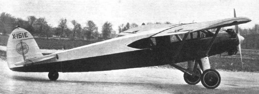
Регистрационный номер: X151E [3] THE VERVILLE "AIR COACH": Side view of this American commercial monoplane, fitted with a 110 h.p. Warner engine.
-
Flight 1929-05 / Flight
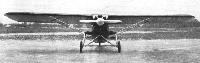
Регистрационный номер: X151E [3] THE VERVILLE "AIR COACH": Front view. Note the method of attaching Oleo struts and front wing-braces.
-
Flight 1931-01 / Flight
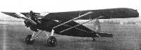
Регистрационный номер: X70W DIESEL-ENGINES: This Verville "Air Coach" will, it is claimed, fly from Chicago to New York at 105 m.p.h. on four dollars' worth of the special fuel oil used. The maximum speed of the machine is 130 m.p.h. The Packard Diesel engine is rated at 225 b.h.p.
-
Flight 1929-05 / Flight
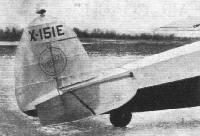
Регистрационный номер: X151E [3] THE VERVILLE "AIR COACH": View showing the neat tail unit, with wheel
-

Flight 1929-05 / Flight
THE VERVILLE "AIR COACH": View showing the interior of the cabin.


- Фотографии