

Описание
Страна : США
Год : 1929
(проект)
Flight, December 1929
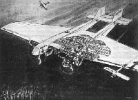
A GIANT AMERICAN MONOPLANE
Designed to carry 160 passengers, the Christmas monoplane has a span of 262 ft. and a power of 8,800 h.p.
SIZE in anything appears to exert a peculiar fascination on the human mind, be the object a railway bridge, a building, a liner, or any other engineering structure. In aircraft also this peculiar fascination is to be found, and the general public has had a good deal of opportunity to be impressed during the past year. So far the outstanding example has been the large Dornier flying-boat Do. X, fitted with 12 "Jupiter" engines. Now, however, news comes from the United States - that land of large-scale undertakings - of a project which, if realised, will make the Dornier Do. X look like a light 'plane!
Unlike the Dornier and other recent large aircraft, the new American machine will be a landplane, thus still further confusing the arguments of the two "schools," one of which maintains that there is a very definite limit of useful size in any heavier-than-air craft, and the other that the limit is not yet in sight, but that if it does exist, it will be reached more quickly in the landplane than in the flying-boat, due to the fact that the loads on a flying-boat hull are distributed while in the case of a landplane they are concentrated on the wheel undercarriage.
The new American project owes its inception to Dr. William Whitney Christmas, vice-president of the General Development Company of Connecticut, and Reid, King and Company, bankers and brokers of Hartford, Conn., are financial sponsors of the enterprise. The chief engineer of the General Development Company is Mr. E. Eliot Green, who was previously aeronautical engineer to the Department of Commerce at Washington, and who designed the Waco machine which won the 1928 Spokane trans-continental air Derby.
It is quite in keeping with the spirit of the undertaking that no less than four machines are being built at once, although prudence might have dictated thorough flying tests with the first machine before proceeding. Any new aircraft type is apt to have teething troubles. Even quite "ordinary" types have been known to exhibit vices that were totally unexpected. However, apparently the engineers of the General Development Company are satisfied, from calculations and wind tunnel tests, that all will be well, and are putting in hand no less than four machines, the cost of which is estimated at two million dollars.
Fundamentally the new American giant, which for convenience we will call the "Christmas," is a twin-fuselage cantilever monoplane, with engines mounted in the fuselages and driving tractor airscrews. Constructionally the machine is an all-metal structure, but unusual in that in spite of its steel construction the covering is of plywood. The passengers' quarters (designed to give accommodation for 160 passengers, exclusive of a crew of 17) are located partly in the wing (which has a maximum depth of 9 ft.) and partly in the two fuselages. The engine arrangement is unorthodox in that, although but two airscrews are employed, there are eight engines, four in each fuselage driving via clutches. Finally, it should be pointed out that two versions will be produced: one for passengers and one for freight.
Technical Data
The following data, unless otherwise stated, refer to the passenger-carrying type.
Length, o.a. 138 ft. (42-1 m.).
Height 31 ft. 6 in. (9-6 m.)
Wing span 262 ft. (80 m.)
Wing area 10,370 sq. ft. (963 m.2)
Wing chord (maximum) 55 ft. (16-75 m.)
Wing chord (minimum) 26 ft. (7-93 m.)
Chord taper 51-6 per cent.
Thickness taper 28-6 per cent.
Aspect ratio 5-76
Aerofoil section Modified CYH
Area of ailerons 720 sq. ft. (67 m.2)
Area of tailplane 1,040 sq. ft. (96-7 m.2)
Area of elevator 560 sq. ft. (52 m.2)
Area of fins 330 sq. ft. (30-7 m.2)
Area of rudders 270 sq. ft. (25-1 m.2)
Dihedral angle 5
Angle of incidence 2
Estimated Weights
Tare weight 90,000 lb. (40,900 kg.)
Fuel and oil 20,000 lb. (9,100 kg.)
Disposable load 35,000 lb. (15,900 kg.)
Gross weight 145,000 lb. (65,900 kg.)
Wing loading 14 lb./sq. ft. (68-5 kg./m.2)
Power loading 16-5 lb./h.p. (7-5 kg./CV.)
Estimated Performance
Maximum speed, sea level 145 m.p.h. (233 km./h.)
Minimum speed, sea level 60 m.p.h. (96-5 km./h.)
Climb to 5,000 ft. (1,525 m.) in 6-5 minutes,
Climb to 10,000 ft. (3,050 m.) in 16-6 minutes
Service ceiling 13,500 ft. (4,120 m.)
Absolute ceiling 15,000 ft. (4,570 m.)
Endurance at cruising speed 7 hrs.
Range at cruising speed 800 miles (1,290 km.)
The disposable load of 35,000 lbs. is made up, in the passenger type, of 160 passengers with their luggage, a crew of 17, and consumable stores. In the freight type of machine there are, of course, no passengers, and the crew is reduced to 9.
Structural Design
The two fuselages are girders constructed of steel tubing, and covered with ply-wood. Their overall length is about 130 ft., and the maximum cross-section measures 18 ft. by 14 ft.
The cantilever monoplane wing is also of steel construction, with, it is stated, two main spars "of heat-treated alloy steel tubes arranged in a novel manner without welding, to permit some flexure without imposing uncomputed stresses." The wing ribs are, generally speaking, of the form of construction used in fuselages of smaller machines, i.e., steel tubes joined by welding. In the interior of the centre-section of the wing the ribs have been designed with arches so as to afford a free lateral passage or corridor without unsightly bracing members. The height in this corridor is sufficient to permit a person of average height to walk from one wing to the other for a distance of approximately 170 ft. In the outer wing portions the rib construction is the usual, with diagonal members.
The undercarriage of a machine weighing something like 65 tons presents a considerable problem. In the Christmas monoplane each fuselage carries an undercarriage consisting of twin wheels of 6 ft. diameter mounted on a very substantial structure and partly enclosed in a streamline casing or "trouser leg." Inside the wheel fairing is a waste heat boiler which supplies heating to the interior of the machine, and here also terminate the exhaust pipes from the engines.
Power Plant Installation
Not the least unusual feature of the Christmas monoplane is formed by the engine installation. In the nose of each fuselage is a unit comprising four separate engines of 1,100 h.p. each, so arranged with clutches and gears that any engine or combination of engines can be "cut in” or "cut out.” The engines are symmetrically arranged around the propeller-shaft, each unit of four engines forming a letter X when seen in front elevation. It is stated that there is ample space between the walls of the engine housing and the engines themselves for engineers to walk about and attend to the individual engines and equipment, ladders giving access to the upper engines. The engines, by the way, are stated to be "chemically cooled at a saving of one-third the weight of radiator and water." Starting is accomplished by an air system comprising a small internal-combustion engine driving an air compressor and a valve mechanism to feed the air to the proper cylinders. One engine is started by this means, the other three of the unit being declutched. When one of the engines has been started, its power is used for starting the other three. The auxiliary engine also drives an electric generator unit for lighting and utility power (i.e., luggage hoists, etc.).
The airscrews are of metal, and are of the variable-pitch type. It is assumed that as gearing is in any case required to enable four engines to drive one propeller, a reduction is employed enabling the large-diameter (34-ft.) airscrews to run at low speed. An examination of the illustrations indicates that a very large percentage of the diameter is shielded, but doubtless this was unavoidable if the space necessary for gears, etc., was to be provided without an undue forward prolongation of the propeller-shaft.
In the engine room, above and behind the power unit, is a balcony for the engineers, with all engine-control levers, tool racks, master ventilators, instruments, propeller pitch-angle adjustment gear, etc. Here also are located two 50-gallon gravity fuel tanks, replenished by mechanical pumps from the main tanks (capacity 3,200 gallons).
Passenger Accommodation
In the passenger-carrying version of the Christmas monoplane accommodation is, as already stated, provided for 160 passengers, located in the forward central portion of the wing, and in parts of the two fuselages. Along the leading edge the passenger accommodation is arranged in 14 compartments, each seating from four to six people. View is provided by transparent sections in the leading edge. All these compartments are served by the corridor which runs laterally from one wing to the other.
The passenger accommodation in the fuselages comprises, in each, a saloon situated aft of the rear spar and on the lower deck of the double-deck arrangement into which the space is divided. Each saloon seats 42 people in single and double chairs, and aft of the saloons are card and smoking rooms. All the cabin compartments are arranged to be made up into berths, if desired.
In the rear portion of the centre section of the wing, aft of the rear spar, i.e., aft of the corridor, is a dining-room with accommodation for more than 40 diners, seated at three-place and six-place tables.
The kitchen is located in the trailing edge of the centre section, just aft of the dining-room, and electric stoves an provided, the current being delivered by the electric generators in the engine rooms. Finally, in the extreme rear portion of the trailing edge is a storage space with electric refrigeration and hoists for handling foodstuffs directly from the ground through a door in the lower wing surface.
Crew's Quarters
The passenger-carrying type will have a crew of 17, including a master, a radio operator, two pilots, a purser, two engine men, two machinists, eight cooks, waiters, and stewards. The crew's quarters are arranged in the fuselages, on the upper deck (above the passenger saloons).
The cockpit for the master and the two pilots forms a bulge on the leading edge of the wing, centrally placed, and non-splintering glass windows enclose practically the whole of the protruding portion, so that the pilots have a good view in almost all directions. The aft portion of the pilot-house is reserved for the master and the wireless operator, and has, in addition to the wireless transmitters and receivers, engine control signals, telephones, a chart table, etc.
We are informed that 62 engineers are now hard at work getting out the production drawings for the new giant monoplanes, and it is hoped that the first machine will be finished and ready for test flights in the autumn of 1930.
- Flight, December 1929
A GIANT AMERICAN MONOPLANE
Фотографии
-
Flight 1929-12 / Flight
AN ARTIST'S IMPRESSION OF THE MONOPLANE: With a span of 262 ft. and a gross weight of 145,000 lbs., this machine will be by far the largest heavier-than-air craft ever constructed.
-
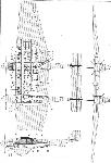
Flight 1929-12 / Flight
THREE-VIEW GENERAL ARRANGEMENT DRAWINGS OF THE CHRISTMAS MONOPLANE: Designed by Mr. E. Eliot Green, of the General Development Co., of Connecticut, this machine is the most ambitious ever produced. In the drawings above the numbers indicate: (1) fuel tanks, (2) mail compartments, (3) luggage, freight and hoists, (4) passenger cabin, (5) purser's office, (6) officers' quarters, (7) observation decks, (8) lavatory and rest rooms, (9) engine control balconies, (10) engine room, (11) kitchen, (12) food storage, (13) dining saloon, (14) control room and pilot house, (15) engine and machinists' section, (16) passenger saloons, (17) smoking rooms.

- Фотографии