Flight, October 1926
THE HANDLEY PAGE "HAMLET”
Three Bristol "Lucifer" IV Engines
IT is now quite a long time ago that official publications, such as annual Reports of the Aeronautical Research Committee, referred to the intention to have built an experimental three-engined mail aeroplane to be fitted with three Bristol "Lucifer" engines. For months - or, in fact, years – nothing materialised, and there was some excuse for assuming that the project had been "shelved." It is, therefore, all the more gratifying to be able to announce this week not only that the project is by no means dead, but that, as a matter of fact, the machine is nearing completion at the Cricklewood works of Handley Page, Ltd., and will in all probability be flying early next week. The machine in question has been named the "Hamlet," and is a thick-wing monoplane fitted with leading-edge slots and trailing-edge slotted flaps. It would seem, however, that the original intention of producing the machine as a mail carrier has been abandoned, since the "Hamlet" appears in the form of a four-seater passenger-carrier.
FLIGHT has urged repeatedly the importance of not losing sight of the three-engined aeroplane of relatively low power. Not that we are under any false impressions as regards the economy of such a type as compared with a single-engined machine of the same power. It is fairly certain that the three-engined type will not be quite as economical as the single-engined, but it is, we think, equally certain that in various parts of the British Empire there are opportunities for the type for use under conditions where the volume of traffic is not yet large enough to justify the employment of a large three-engined machine, but where the reliability of the three-engined arrangement is more essential than maximum economy. It is therefore with considerable pleasure that we welcome the new Handley Page "Hamlet," and we sincerely trust that it will not prove a "ghost" in any sense of the term.
As already mentioned, the new "Prince of Denmark" is a monoplane incorporating the Handley Page-Lachmann slotted aerofoil, and, incidentally, apart from having the distinction of being the first modern three-engined aeroplane of low power, the "Hamlet" is the first civilian machine with slotted wings to be ordered by the British Air Ministry.
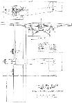
The general arrangement and lay-out of the "Hamlet" are shown in the accompanying scale drawings, while some of the constructional features arc illustrated by sketches. It will be seen that the monoplane wing is of rectangular plan form, while the wing section (RAF 31) is uniform from root to tip, and the wings are set at a pronounced dihedral angle. For a total loaded weight of 5,000 lbs. the span loading is 0-54, a fairly high figure for a machine of this size, and which should thus keep the induced drag down to a rather low figure. (For instance, at an indicated air speed of 100 m.p.h. the induced drag for this machine would be approximately 115 lbs., corresponding to a thrust horse-power of about 31, or, assuming a propeller efficiency of 75 per cent., about 41 b.h.p.)
So far, therefore, as the wing arrangement itself is concerned, the new Handley Page "Hamlet" should be very efficient, especially as the section employed, that known as RAF 31, has a good L/D ratio when in its normal form. The addition of the slotted leading edge and slotted flaps is admittedly something of an experiment, and has not, as far as we are aware, been tried on this section at full scale before. The maximum lift coefficient of RAF 31, according to full-scale tests carried out on a Bristol Fighter (see Reports and Memoranda No. 990, Full Scale and Model Measurements of Lift and Drag of Bristol Fighter with RAF 31 Wings), is 0-635 at 18° incidence. We believe it is estimated that the stalling speed of the "Hamlet" will be in the neighbourhood of 47 m.p.h., which would correspond, with a wing loading of 12-9 lbs./sq. ft., to a maximum lift coefficient (full scale, of course) with slots open, of 1-1 (absolute). Presumably, therefore, experiments with slotted models of RAF 31 in the Handley Page wind tunnel have indicated that an increase in lift coefficient of this order may be expected.
Constructionally the leading edge slots of the "Hamlet" wings are of interest on account of the fact that the auxiliary aerofoil is not, as in several previous Handley Page machines, single surfaces of sheet Duralumin, but built-up aerofoil sections shaped so as to fit, when the slot is closed, snugly against the nose of the main aerofoil. Thus, presumably, the wing will have as low a drag with slot closed as the normal RAF 31 section. The auxiliary aerofoils are operated by torque tubes from the cockpit, and are interconnected with the slotted trailing-edge flaps, the outer portions of which, of course, retain their differential action as ailerons.
Although the monoplane wing of the "Hamlet" promises to be of very good aerodynamic efficiency, there would appear to be a probability that this efficiency may be somewhat lowered by placing two engines on the wing-bracing struts. This is almost inevitable - at any rate, with radial air-cooled engines - and must be regarded as the price to be paid for the extra reliability which the three-engine arrangement offers. Behind the two outboard engines are placed the oil tanks, of conical shape, but otherwise it is not intended to streamline the wing engines. The fuselage is of good shape, and is of fairly small cross-section considering that the machine has been designed as a passenger-carrier. On the whole, it can, we think, be said that the "Hamlet" is of clean design for a machine of this type, and we understand that the estimated top speed is in the neighbourhood of 118 m.p.h. (190 km. hr.), which, if attained, is distinctly good for a three-engined aeroplane of this power and wing loading.
Constructional Features
Generally speaking the "Hamlet" follows normal Handley Page practice as regards construction. The fuselage is of the girder type throughout, including the cabin portion, and is fabric covered. In a few instances short lengths of the bracing wires cross the cabin windows, but these lengths are so short as to interfere but little with the view, which, on account of the monoplane wing, is very good. Probably the fact of the cabin being fabric covered may serve to reduce to some extent the rather unpleasant "drumming" which one is apt to get in most cabin machines.
The wings are of fairly normal composite construction, with box-section spars having three-ply walls, and wooden ribs. The shaping of the front and rear slots has naturally necessitated rather careful work on the leading and trailing edges of the main wing, three-ply being the material used for the immovable portions of the slots. The wing bracing is in the form of large-diameter steel tubes meeting the two main spars and converging at a point on the lower longerons of the fuselage.
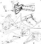
The engine mountings are also tubular, with the exception of the actual engine "rings," which are machined from the solid into a channel section Details are shown in our sketches. Two petrol tanks are mounted inside the wing, one on each side of, and just outside, the fuselage. From the tanks the petrol flows by gravity to a distributor box in the cockpit, from which again, via suitable petrol cocks, either or all engines can be supplied from either or both tanks.
The pilot's cockpit, situated between the front wall of the cabin and the bulkhead behind the central engine, is very roomy and affords an excellent view. The cockpit is particularly plentifully supplied with "gadgets," since there is not only the slot operating gear to attend to but also a complete wireless installation. The various controls are, however, conveniently placed, and the engine controls are of very simple type, so that in spite of the three-engined arrangement the number of controls is not excessive.
The Cabin
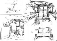
From the pilot's cockpit a door on the starboard side leads to the cabin, which has seats for four passengers, of whom two face forward and two aft. The seat in the front starboard corner of the cabin is hinged so as to swing out of the way when it is desired to pass from cabin to cockpit or vice versa, and a handle projects from this seat into the cockpit so that the pilot can, when this seat is not occupied, swing it out of the way and open the communicating door. The seats are well upholstered and very comfortable, and provision has been made for carrying permanently a table which, when in use, rests on the tubular rails of the nets on the side walls of the cabin. The entrance door is on the port side, and the machine is so designed that passengers can step straight into the cabin from the ground without the use of steps. Emergency ripping panels are provided in the roof, and the windows are provided with silk roller blinds in place of the more usual curtains. Altogether the cabin is most comfortable and in spite of the fact that it is not of very large dimensions (104 cubic feet) does not at all, for some reason, give one the impression of being shut into a cramped space which one frequently gets in very much larger cabins. At the moment it is, of course, impossible to say how far the cabin of the "Hamlet" will be noisy or not. This can only be decided after prolonged flying in the machine. But otherwise the cabin is exceptionally comfortable, and it is quite evident that the designers have aimed at comfort rather than weight-saving in its equipment, a policy which is entirely justified.
The main data relating to the Handley Page "Hamlet" are as follows :- Length over all 34 ft. 10 in. (106 m.); wing span 52 ft. (15-85 m.); wing chord, 8 ft. (2-435 m.); wing area, .388 sq. ft. (36 m.1); weight of machine bare, 3,105 lbs. (1,410 kg.); weight of instruments, cabin equipment, etc., 270 lbs. (122-7 kg.); petrol, 74 gallons (337 litres); oil 7 gallons (31-9 litres); weight of pilot 180 lbs. (82 kg.). Useful load (4 passengers and luggage), 800 lbs. (363 kg.). Total loaded weight, 5,000 lbs. (2,270 kg.). Wing loading, 12-9 lbs/sq. ft. (63-2 kg m!). Power loading (3 engines at 120 h.p.), 13-9 lbs./h.p. (6-32 kg/h.p.). "Wing-power" (i.e. ratio of horsepower to wing area), 0-928 h.p./sq. ft. (10 h.p./m2). Power loading with 2 engines running, 20-8 lbs./h.p. "Loading-figure" (i.e. power loading multiplied by square root of wing loading) 50. Estimated top speed, 118 m.p.h. (190 km./h.). Cruising speed 100 m.p.h. (161km. h.) Landing speed 47 m.p.h. (75-7 km., h.). Speed with two engines running, 90 m.p.h. (145 km./h.)
- Flight, October 1926
THE HANDLEY PAGE "HAMLET”
Фотографии
-
Flight 1926-10 / Flight
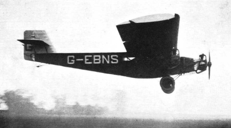
Регистрационный номер: G-EBNS [7] RETURNING FROM CROYDON: The Handley Page "Hamlet" arriving at Cricklewood after its visit to the Croydon demonstration.
-
Flight 1926-11 / Flight
Регистрационный номер: G-EBNS [7] AN INTERESTING THREE-ENGINED AEROPLANE: Four views of the Handley Page "Hamlet" (three Bristol "Lucifer" engines), which was illustrated and described in detail in our issue of October 14, 1926. In the three-quarter front view the leading edge slot is closed, while in the side view it is shown open.
-
Flight 1926-10 / Flight
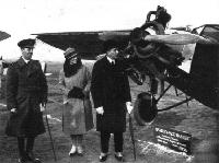
Регистрационный номер: G-EBNS [7] Just the thing for Australia?: Mr. Bruce, Prime Minister of Australia, and Mrs. Bruce interested in the Handley Page "Hamlet" three-engined monoplane.
-
Flight 1927-06 / Flight
Регистрационный номер: G-EBNS [7] Handley Page "Hamlet" (2 Armstrong-Siddeley "Lynx"). Originally this machine was produced as a three-engined commercial monoplane, and as such was, at the time, the smallest machine of this type in existence. More recently the "Hamlet" has been altered to a twin-engined machine, the place of the central engine now being taken by a "plain nose." A feature of this machine is that it is fitted with the Handley Page patented slot and flap gear, by means of which, for a given wing loading, a lower landing speed is attained. It is, presumably, mainly on account of the latter feature that the "Hamlet" is included in the Parade.
-
Flight 1927-08 / Flight
Регистрационный номер: G-EBNS [7] A Princely Nose: The Handley Page "Hamlet" has now been fitted with two Armstrong-Siddeley "Lynx" engines. A false "nose" rounds off the fuselage where formerly a third engine was placed. In the cockpit is seen Squadron-Leader England, who has now joined the Handley Page staff.
-
Flight 1939-06 / Flight
Регистрационный номер: G-EBNS [7] The Hamlet light commercial monoplane could have one, two or three engines. It is seen here with two Siddeley Lynxes.
-
Aeroplane Monthly 1979-08 / Cricklewood /Gone but not forgotten/ (4)
Регистрационный номер: G-EBNS [7] The modified H.P.32 Hamlet (it was originally a tri-motor) leaps into the air at Cricklewood in May 1927. Powered by two Armstrong Siddeley Lynx IIIs, the Hamlet was designed as a 6-7 seat taxi-aircraft.
-
Flight 1926-10 / Flight
THE HANDLEY PAGE "HAMLET": 1 represents a peep into the cabin, through the open door in the port side. The door leading to the pilot's cockpit can be seen open and the seat in the front starboard corner is tilted out of the way of the door. In 2 is given a view inside the cabin looking forward, with the door to the cockpit closed and the seat in its normal position. Note the roller blinds and the net racks on the sides, which serve as supports for the removable table (shown in dotted lines). 3 is a side elevation of the back seat, showing method of supporting it cantilever fashion. 4 is a view inside the cabin looking aft. The flap in the back rest covers the handle which releases the catches securing the chair in position. When this is released the back seat can be moved to various positions.
-
Flight 1926-10 / Flight
THE HANDLEY PAGE "HAMLET": Some constructional details. 1 shows the very substantial fitting at the root of the wing struts, and also the arrangement and support of the port wing engine control which runs along the front of the front strut in guides. The connecting link between the crank coming out of the fuselage and that on the control bracket is omitted. In 2 is shown the mounting on the wing tubes, of tte starboard wing engine as seen from behind The small flat-topped brackets are for the support of the oil tank. The engine ring is machined from the solid and has packing pieces at intervals, as shown in 2A. Details of the leading-edge auxiliary aerofoil are shown in 3. The covering is Duralumin sheet put on over wood ribs. One of the brackets supporting the slotted trailing edge flaps is shown in 4, while 5 illustrates the manner of attaching the bracket to the mam spar.
-
Flight 1926-10 / Flight
Handley Page "Hamlet" 3-120 hp. Bristol "Lucifer IV" Engines
- Фотографии


