

Описание
Страна : США
Год : 1919
Единственный экземпляр
Flight, March 1920
THE HILD-MARSHONET SPORTPLANE
THE Hild-Marshonet sportplane, which hails from the United States of America, was designed to meet the demand for a moderate-price aeroplane, built of the best materials and workmanship. This little machine, the outcome of 10 years' experience in aeroplane engineering, possesses several noteworthy features, especially in connection with machines of its class. The particular machine shown in the accompanying photographs and scale drawings is fitted with a 20 h.p. two-cylindered air-cooled engine, but a second model, similar in every other detail, is being equipped with a four-cylindered water-cooled engine developing 40 h.p. at 1,100 r.p.m., and weighing 135 lbs. This engine, which was used with success in 1914, was designed by Mr. James C. Spainhour, M.E., who is associated with the designers of the Hild-Marshonet aeroplanes, and will be put into production for use exclusively in both the single- and two-seater Hild-Marshonet machines.
It will be seen that the upper main planes, which have no dihedral, have their leading edges swept back, whilst the lower planes are given a "sweep forward" and set at a dihedral angle of 6°. The top plane is staggered forward, the angle of stagger at the body being 40°, and, by virtue of the "fore-sweep" of the lower plane, at the tips, 12°. This unusual lay-out of the wings not only makes for stability both lateral and longitudinal, but allows an excellent range of vision.
The chord of the top plane tapers from 5 ft. at the root to 3 ft. at the tip, the curvature and depth of the ribs varying to suit the chord. The lower planes also taper in chord from 4 ft. 6 ins. to 3 ft. N.P.L. wing section No. 4 is employed, this section having a high lift and a good L/D for the 4° angle at which the planes are set.
The main spars are of I-section spruce, laid out in "A" formation - converging at the outer extremities. The ribs are of boxwood with spruce cap strips, secured with brass screws. The fabric covering is sewn on the wing framework, and treated with five coats of Dupont dope and a final coat of varnish.
A single interplane strut, more or less of streamline section, is fitted on each side of the body, and above the latter an inverted V pylon forward and a pyramid of four struts aft, serve as attachments for the upper planes. The interplane struts are built up of two layers of three-ply veneer, reinforced at the centre with a bevelled spruce strip, and at the edges with aluminium, all securely riveted together. The steel strut attachments are also riveted to the strut. There are two flying cables and one anti-lift cable each side, all of 3/16 in. diameter, and no turnbuckles are used. On the rear pylon, within easy reach of the pilot, is a quick-release lever to which are secured the anti-lift cables, and by means of which the pilot may relieve the tension of the cables, thus enabling the main planes to be removed single-handed, with the greatest possible ease. This, of course, is a great advantage in a machine of this type, enabling it to be stored in a very small space (not more than 9 ft. by 20 ft.), and necessitating the minimum of labour and attention in erecting and dismantling. The interplane struts, it should be mentioned, fold against the surface of the upper planes and are secured in place by a catch. The ailerons are hinged to the rear spars of the upper planes.
The tail planes consist of a triangular horizontal stabilizing surface, to the trailing edge of which are hinged two elevator flaps, a vertical fin and a balanced rudder. The horizontal stabiliser, which is set at 0° a few inches above the line of thrust, is built up of spruce, and is mounted above the fuselage on the vertical fin. Both the rudder and elevators are constructed of steel tubes and wood ribs. The control cables are in duplicate and pass through the fuselage, the rudder cables entering the latter at the top, through copper tube guides, and the elevator cables at the sides.
The fuselage is exceptionally strong, being built up of three-ply veneer, reinforced with aluminium and steel bulkheads riveted to the veneer. The cowling is of aluminium, reinforced with steel braces, which are also secured with bolts to the fuselage. The cockpit is comfortably upholstered, and getting in and out is easily accomplished, the pilot using the top of the fuselage immediately behind the cockpit as a step - this being a height of only 18 ins. from the ground.
The landing chassis is of the V-type, of steel tube construction streamlined with wood fairings wrapped with linen. Each V is connected by a cross tube in front of the axle, and the front bay is wire braced. The axle is 1 1/4 ins. diameter, and the wheels are 20 ins. by 3 ins. (larger wheels, 26 ins. by 3 ins. will be fitted in future models). The tail skid is a combination of steel and rubber, and acts as a brake on alighting.
The accompanying curves show the calculated performance of the 40 h.p. model. It is proposed to put both single-seater and two-seater machines in production at an early date, and it is hoped to fix the prices somewhere in the neighbourhood of $2,000 and $2,400 respectively. The principal characteristics are as follows :-
Span
Top plane 24 ft
Lower plane 19 ft. 3 ins.
Chord
Top plane 5 ft. to 3 ft.
Lower plane 4 ft. 6 ins. to 3 ft.
Gap 3 ft. to 4 ft.
Overall length 19 ft.
Angle of incidence 4°.
Wing section N.P.L. No. 4.
Total area of main planes 160 sq. ft.
Area of
Ailerons (two) 20 sq. ft.
Stabiliser 6 sq. ft.
Elevators 9 sq. ft.
Fin 3 sq. ft.
Rudder 6 sq. ft.
Factor of safety throughout 7
Weight of machine, empty 450 lbs.
Weight fully loaded, all on for three hours 700 lbs.
Speed range (40 h.p. engine) 35-65 m.p.h.
Climb 780 ft. per
- Flight, March 1920
THE HILD-MARSHONET SPORTPLANE
Фотографии
-
Flight 1920-03 / Flight
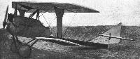
Three-quarter front view of the Hild-Marshonet sportplane
-
Flight 1920-03 / Flight
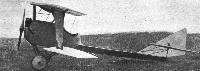
Side view of the Hild-Marshonet sportplane
-
Flight 1920-03 / Flight
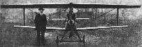
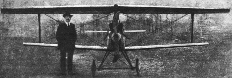
Front view of the Hild-Marshonet sportplane
-
Flight 1920-03 / Flight
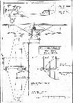
THE HILD-MARSHONET SPORTPLANE: Plan, side and front elevations to scale


- Фотографии