Jane's Encyclopedia of Aviation
Loening Air Yacht (USA)
In 1928 the Loening Aeronautical Engineering Corporation became a division of the Keystone Aircraft Corporation. The Air Yacht - produced during the 1920s by Loening for commercial and military operation - had no relation to the later Keystone Air Yacht, with the exception that both were flying-boat types. The Loening Air Yacht was powered by a single Liberty engine, mounted as a pusher. It accommodated four passengers. Eight or nine were produced in 1923 for the USAAS as S-1s, intended to be used as communications aircraft between island bases. Three commercial Air Yachts were of special interest as they were built for the New York - Newport Air Line.
Показать полностьюShow all
Flight, October 1921
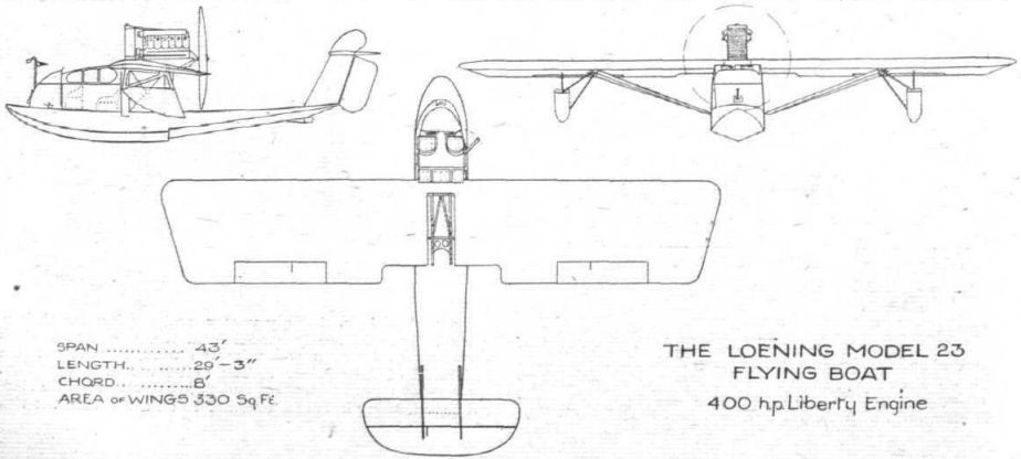
THE LOENING MODEL 23 FLYING BOAT
A MORE or less original type of flying boat has just been turned out by the Loening Aeronautical Engineering Corp., of New York, U.S.A., to the designs of Grover C. Loening. During an altitude test on August 16 last, at Port Washington, this machine put up what is claimed to be a record, for seaplanes carrying three passengers, by attaining an altitude of 19,500 ft. The "Flying Yacht," as it is called, was piloted on this occasion by David McCullock, and the passengers carried were Grover C. Loening, L. R. Grumman, and L. d'Orcy, the latter acting as observer for the Contest Committee of the Aero Club of America.
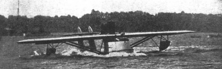
As the machine got away it was noticed that she rode the sea easily, there being no porpoising whatever, and also that the raised cockpit effectually protected the crew against the spray created as the boat gathered speed. The take off occurred after a short run, and circling once round the bay, the pilot started climbing in wide curves. At 6,000 ft. the air became somewhat bumpy, and it was gratifying to note how promptly the machine answered the controls. Within the next thousand feet the air became calmer, and at 14,000 ft. the temperature dropped considerably, it being necessary to cover up portions of the radiator with strips of rubber, as a shutter arrangement was not fitted. The peak of the climb, 19,500 ft., was reached in 48 mins., the air speed during the climb being about 85 m.p.h.
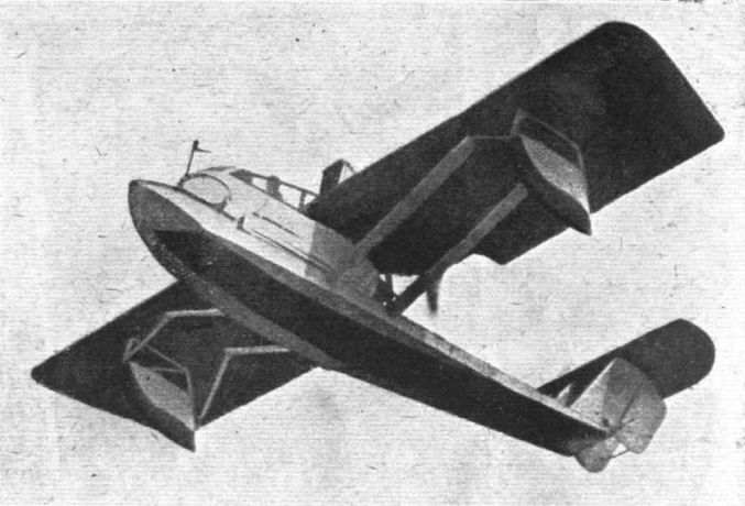
As may be seen from the accompanying general arrangement drawings - for which we are indebted to our American contemporary Aviation - the Loening Model 23 is a monoplane pusher flying boat. It is of the long hull type, as distinct from the short hull or bat boat type, but it differs from the accepted idea of flying boat hulls in one fundamental point. The flotation system comprises a completely sealed unit, or pontoon. This arrangement effectually prevents the flotation system from losing a portion of its buoyancy through the shipping of water when the machine is taxying, while on the other hand the cockpit is raised sufficiently high over the pontoon to give the crew ample protection against spray. Another advantage with this type of construction is that, given the same displacement required to float a machine, the sealed hull can be made much stronger, or lighter, than could be achieved in a hull affording accommodation to the crew, because with the latter type the hull structure must have a much larger volume. Thus the Loening Model 23 may be said to be a compromise between the boat and float type of seaplane, for it incorporates the low resistance of flying boats, due to the absence of parasite structures between wings and floats, while on the other hand it retains the main advantages of the float type, viz.: it is practically unsinkable.
The hull is of very sturdy construction, the bottom planking consisting of two-ply spruce, with fabric laid in marine glue between, and one outer layer of 1/4-inch ash. The total thickness of the bottom throughout its length is 1/4 inch. The sides and top are of 1/4-inch mahogany veneer, and the framework is of spruce. It is internally braced by a triple truss with cross wires, which in itself will take the tail load without the assistance of the planking. The hull has a 21° V bottom throughout its entire length, and is fitted with a single step. All the planking is bolted together to do away with the risk of screws or rivets pulling out under the strain.
It will be seen in the plan view that the hull is of practically was adopted with the particular view to oncoming porpoising, and this has been borne out in practice. The hull is subdivided into 16 water-tight compartments, each being provided with its individual hand hole and ventilating tubes. Incidentally, for the altitude test a 1/16-inch hole was made in each hand-hole cover in order to prevent the hull "blowing up" owing to the difference in atmospheric pressure at high altitudes.
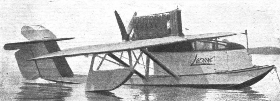
The pilot's and passengers' cockpit is built up above the deck on the fore part of the hull, and has accommodation for five persons - two, including the pilot, sitting forward on separate seats, while three are seated aft. Ample leg-room is provided for, and there is a general air of roominess about the cockpit which should appeal to the owner pilot. Access is obtained through a door in the starboard side of the cockpit, which opens on to a running board extending round the front of the cockpit and sufficiently wide to enable the crew easily to walk along it. The 400 h.p. Liberty engine - which is fitted with a 4-bladed Hartzell propeller - rests on two ash bearers supported on two M struts built integral with the hull. The space between the arms of the M is utilised for housing the petrol and oil tanks, which are under pressure. The whole structure is carefully streamlined, the cowling blending into the rear portion of the cockpit. The engine and radiator are very accessible from the cockpit, the mechanic using his seat as a stand.
The sides of the cockpit consist of a 1/4-inch veneer framework, with aluminium covering, which is bolted on to the hull. Two separate wind-shields are provided for the pilot and the passenger sitting beside him. On the nose of the cockpit a small staff carries a metal pennant which answers the purpose of a side-slip indicator - based on the famous and ancient "string" employed on the early Wright machines. The pilot tube for the speed indicator is also mounted on this staff. A 57-lb. anchor is carried on the bow for mooring the boat when no buoys are available.
For the wings, which have no dihedral or sweepback, the standard structure adopted by the Loening Co. for their new Model 21 fighting monoplane is employed. The wing floats are supported by vertical three-ply struts built integral with the structure, and are braced by additional struts against side strains. The weight of the wing structure complete is 290 lbs. The tail unit consists of two parallel vertical fins mounted on the outer corners of the hull. These fins carry a one-piece horizontal stabiliser, on top of which are two smaller vertical fins, and a single unbalanced elevator hinged to the trailing edge of the stabiliser. Two unbalanced rudders are hinged to the vertical fins. The stabilizer incidence can be varied by means of a hand wheel in the cockpit.
It is of interest to note that the Model 23 "Yacht" represents the culmination of the efforts made by Grover C. Loening during the past ten years with a view to producing a seaplane that would be both airworthy and seaworthy. His earliest machine, of 1911, was, in fact, very similar in general outline to the Model 23 described above.
The following are the principal characteristics of the "Yacht" :-
Span 43 ft.
Chord 8 ft.
Overall length 29 ft. 3 ins.
Height 8 ft.
Angle of incidence 4 1/2 deg.
Area of wings (including ailerons and struts) 330 sq. ft.
Area of ailerons 22 sq. ft.
Area of tail plane 23-5 sq. ft.
Area of elevator 19 sq. ft.
Area of fins 24 sq. ft.
Area of rudders 16-5 sq.ft.
Weight empty 2.200 lbs.
Weight fully loaded 3,550 lbs.
Weight (sq. ft.) 10-7 lbs.
Weight (h:p.) 8-5 lbs.
Factor of safety 8-9
Maximum speed 125 m.p.h.
Cruising speed 110 m.p.h.
Climb in 10 minutes 9,500 ft.
Показать полностьюShow all
Flight, April 1923
THE LOENING CONTROL
EARLY this year some tests were carried out in America with a new type of aileron control, designed by Grover C. Loening, who has produced several successful types of aeroplanes. These tests were made over the East River, N.Y. (where the factory of the Loening Aeronautical Engineering Corporation is located), under by no means ideal weather conditions, a high north-westerly and gusty wind prevailing at the time. The machine used was the Loening monoplane air yacht, owned by Harold S. Vanderbilt, whose pilot, S. W. Cogswill, carried out the tests.
This new invention, which is called a lateral "pressure equaliser," is mounted on the extreme tip of each wing, and departs radically in its effect from the orthodox forms of lateral control, where the aileron is hinged to the rear spar of the wing, at the trailing edge. Recent high-speed performances of aeroplanes have demonstrated that as the speed increases the ordinary aileron type of control becomes less effective and has a tendency to put twisting stresses on the wing, which neutralise the controlling effect of the ailerons and renders the machine stiff on the controls.
In the Loening "pressure equaliser" this state of affairs is avoided, because the controlling surface - which, as with ailerons in general, is intended to give more lift on one wing than on the other - is mounted forward of the centre of the wing, so that the effect of the extra lift or pressure produced by the aileron, tending to twist the wing causes this twisting stress now to be completely reversed in favour of the lateral control instead of against it. Thus the operation of the "pressure equaliser" tending to lift one side of the wing causes the angle of incidence of that side of the wing to increase, thus still further amplifying the controlling power and completely equalising the twisting stresses induced by the orthodox type of control.
In construction this "pressure equaliser" is quite simple. A small section of the leading edge of the wing is extended out beyond the tip, and to this extension is hinged the equalising flap, which is controlled from the pilot's cockpit through cables and levers. This device can be applied to any type of 'plane, but is most suitable for monoplanes owing to the greater depth of chord obtaining in this type of machine.
Mr. Loening claims that this new control is so effective that the use of the trailing edge aileron now in general use may be eliminated entirely and much more controlling power obtained with the new device with one-quarter of the area of movable surface, and with a great reduction in the energy applied to the control stick. He believes also it emphasises the qualities of the monoplane in comparison to other types of machines in that it is now possible to preserve lightness and simplicity without any sacrifice of control whatsoever, and to obtain to the best advantage the superiority in speed and climbing power.
Показать полностьюShow all

 Wiki
Wiki