
 Wiki
Wiki Flight, November 1922
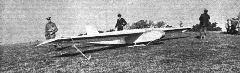
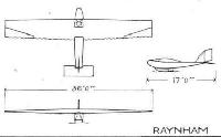
THE HANDASYDE MONOPLANE GLIDER
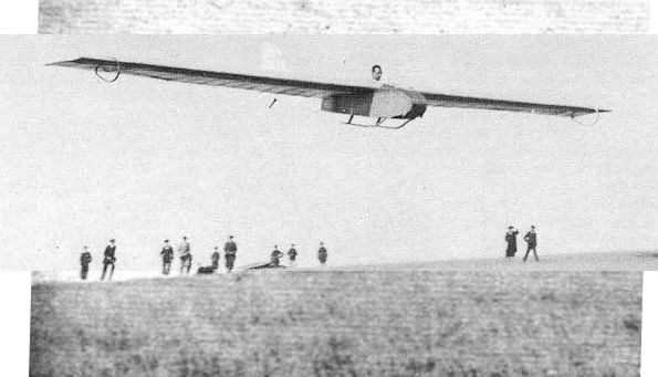
The Machine on which Raynham Remained Up for Nearly Two Hours
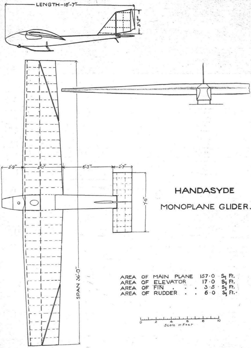
THE Handasyde Monoplane Glider was designed by Raynham and Sydney Camm in conjunction with Mr. Handasyde. It was built for the Handasyde Aircraft Co. by the Air Navigation Co. (Bleriot's) at Addlestone. It is characterised by a large tapered cantilever wing, whose section at the root, and for a distance of 4 ft. out from the centre line, is that known as Gottingen No. 441. The, fuselage is of very small cross-sectional area, and is constructed of a light framework of spruce, covered with three-ply. In order to lighten the fuselage the ply-wood covering has had circles cut out in each bay, but fabric covering is put on over the three-ply. It would appear that the particular method of cutting away is open to criticism, and it might have been better to leave diagonal strips in each bay, cutting away triangular pieces only, as in this manner each bay would have been triangulated, which can scarcely be the case with the whole centre cut away. However, in spite of this the fuselage appears to be very rigid, also against torsional stresses, and no difficulty whatever was experienced in this respect. At the stern the body terminates in a horizontal strip about 2 ins, deep, to which the balanced elevator is hinged. A light tail skid keeps the elevator from touching the ground in getting off and landing.
In front the fuselage shows a rounded nose (as seen in plan), and the top longerons slope upwards slightly from the rear spar to the nose. The wing spars are secured to the fuselage by long "stirrups" of duralumin, and no external bracing of any sort is provided, the wing being so constructed as to be very rigid both in direct bending and in torsion.
The wing is built up on two spars, formed by top and bottom flanges of spruce, with a three-ply web on one side only, except at certain points where both sides of the spars are covered with three-ply. In order to strengthen the wing the covering over the inner portion is three-ply wood underneath the fabric. This ply-wood is used both on upper and lower surfaces, being in fact bent over the leading edge and extending back, top and bottom, to the rear spar, which is placed well forward in the section so as to give a flexible trailing edge. The latter is formed by a wire. The taper is fairly pronounced, both in plan and thickness, and the wing is given a "humped" appearance by the fact that the taper in the spars is greater on top than underneath. As a matter of fact, we believe that at the tip the lower surface of the main spar is only about 1 1/2 ins. above the longeron, while the upper surface slopes down to it.
Triangular ailerons are fitted at the tips, being hinged to strips carried on the overhanging portion of the outer ribs. A light stringer runs through the whole wing a few inches forward of the wire trailing edge, and, although not taking any part in the direct loads, serves to stiffen the wing structure, notably the ribs, very considerably.
The controls are of somewhat unusual type. The "joy stick" is placed on the right, and is used for operating the balanced elevator only. The rudder is worked by two pedals, so that when the pilot's feet are off the pedals the rudder cables hang quite slack. This gave many the erroneous impression that the cables were broken. The aileron control is of the simplest possible type. In fact, there is none, in the ordinary sense of the term. The ailerons are operated by the pilot gripping the aileron cable with his left hand and pulling the cable to one side or other. As the cable passes along the front spar, in front of the pilot, it was decided that a lot of unnecessary complications, such as pulleys, crank-levers, etc., could be dispensed with by using this form of control, and Raynham, once he had got used to the controls, found no difficulty in handling the machine. At first his fingers used to get cramped with gripping the bare cable, but later a guard was fitted, and tape wrapped around the cable, which improved matters considerably.
The vertical tail members consist of a triangular fin and a rudder of approximately parallelogram shape. The first rudder fitted was found to be too small, and a larger one was made, which gave some improvement. An addition to this was, however, found advisable, and this is shown in the side elevation of the general arrangement drawings. As a matter of fact we rather think that the rudder was large enough, and that what was really the trouble was that there was not sufficient fin area forward (the fuselage being of small depth) to afford a pivot for the machine to turn upon. In other words, the machine would probably fly somewhat like the old box kites, which had no fin surface forward, and which had to be assisted in a turn by the ailerons.
The pilot's cockpit is a very small one, and we believe that actually Raynham was measured for it. He certainly seemed to fit it with but little room to spare. The cockpit is placed between the main wing spars, and is covered with a three-ply panel in which is cut a hole for the pilot's head. We believe that when flying Raynham found this position quite comfortable, as there was very little draught, the air probably shooting up above the pilot's head. Let into the coaming over the cockpit is one of the new Smith and Sons' air speed indicators.
The undercarriage consists of two ash skids, anchored at their front ends to the lower longerons, and supported at the rear by short struts which are so pivoted that they are free to swing back as the load comes on the skids. The machine pulls up almost instantly on touching, and as the wings are very close to the ground, and the tips protected by cane loops, the machine never showed any tendency to turn over. Furthermore, the low wing position appears to give a certain amount of "cushioning" effect in landing, while assisting the machine to get off at a very low speed.
When the sluggishness of the directional control has been remedied the Handasyde monoplane should be a very excellent machine, as it certainly rises in quite low winds and appears very steady laterally. That Raynham should have been able, on his fifth flight, to remain up for nearly two hours is a remarkable testimony not only to his skill but also to the general design of the machine. We hope to hear of further flights being made on it as soon as it has finished its "show" at Selfridge's, and the few ribs damaged in transport have been repaired.
- Flight, November 1922
THE HANDASYDE MONOPLANE GLIDER
Фотографии
-
Flight 1922-10 / Flight
Raynham's Glider pegged down on the summit of Itford Hill.
-
Aeroplane Monthly 1979-09 / D.Brown - Wings over Sussex (1)
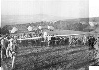
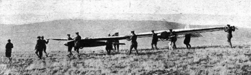
Carrying Raynham's Glider up to the top of Itford Hill. In the background may be seen the five tent hangars used for housing the machines.
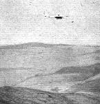
Looking north-west from Itford towards Lewes. -
Flight 1922-10 / Flight
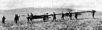
WILLING HELPERS: A detachment of the R.A.F. carrying Gordon England's and Raynham's gliders to the top of the hill.
Другие самолёты на фотографии: Gordon England glider - Великобритания - 1922
-
Air Enthusiast 1971-09 / In print
The first glider described in “British Gliders and Sailplanes” is this 1922 single-seater designed by G A Handasyde, F P Raynham and Sydney Camm and built by Air Navigation Co for Handasyde Aircraft Co.
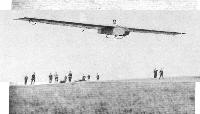
Raynham making a short flight, October 15, to test his machine. -
Flight 1922-10 / Flight
Raynham starting off on his 11 1/2 minutes' flight.
-
Flight 1922-11 / Flight
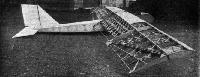
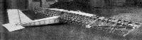
The Handasyde Glider: View of the machine in skeleton, taken during construction at Addlestone.
-
-

Flight 1922-11 / Flight
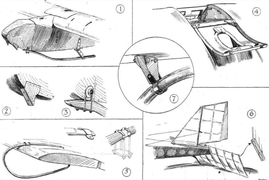
THE HANDASYDE MONOPLANE GLIDER: Some constructional details. 1. The nose of the machine, showing landing skids. 2. One of the cleats which support the launching rope during the start. 3. Front attachment of landing skid. 4. Cover over cockpit thrown back. When the cover is pulled down the pilot's head projects through the small opening. Note the hand guard on the aileron cable. 5. Details of a wing tip skid. 6. The tail. 7. Detail of tail skid attachment.
-
Flight 1922-10 / Flight
Raynham
-
Flight 1922-11 / Flight
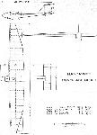
Handasyde Monoplane Glider


- Фотографии