
 Wiki
Wiki Flight, May 1923
THE GNOSSPELIUS LIGHT 'PLANE
700 C.C. Blackburne Engine
AERODYNAMIC efficiency is the keynote of the light 'plane which Major O. T. Gnosspelius has designed, and which was recently finished at the Rochester works of Short Brothers. The new machine, as distinct from the majority of ordinary aeroplanes, was designed from the aerodynamic point of view entirely, and, having got the efficiency as good as seemed possible without a great deal of further experiment, the designer set to work to see how the shapes which he had found by experiment to be good could be translated into a sound aeroplane structure. This is not to be taken to mean that the construction is in any way inferior, but merely that where, as frequently happens, aerodynamic and structural requirements clashed, the former were given preference. Perhaps an illustration may help to explain what we are driving at. Had Major Gnosspelius given preference to structural considerations he would undoubtedly have chosen a much thicker wing section, and trusted to luck to get the best possible aerodynamic results from it. Instead he discovered a wing section which, although deeply cambered, was not very thick, but which gave good results. He chose this section deliberately, fully realising that in so doing he was setting himself a considerable structural problem. How he solved that will be related in its proper place, but the example given shows that this designer, at any rate, is not content to take the line of least resistance (if a "pun" may be allowed, that is, of course, exactly what he has done) and hoping for the best.
In view of this somewhat unusual line of attack, a few words concerning the starting point may not be without interest. In a paper read before the Institution of Aeronautical Engineers (published in FLIGHT of December 21, 1922), entitled "Experimental Data Without a Wind Tunnel," Major Gnosspelius described the pendulum apparatus which he and other members of Short's designing staff developed for purposes of testing scale models of wings or of complete machines. On this pendulum the models are mounted, with the wings parallel to the pendulum arm, and the tests are carried out by raising the pendulum to a horizontal position, releasing it from there and noting how far it swings up on the other side of "dead centre." This gives an indication of the resistance of the model, while the lateral deflection of the pendulum at its lowest position gives an indication of the lift.
On this pendulum Major Gnosspelius has tested a large number of models, and he has discovered several very interesting, and to some extent inexplicable, things. First of all he tested certain wing sections of which data were already available. He found that reasonably good agreement was obtained. He then tested other wing sections, as, for instance, the R.A.F. 19, which was found by model tests at the N.P.L. to give a very high lift. On the pendulum this high lift was not attained. Now the curious fact about this test is that when tested on the full scale R.A.F. 19 does not give the high lift which wind tunnel tests on models indicated. The logical conclusion seems to be that the pendulum, in certain circumstances, is in better agreement with full scale work than is the wind tunnel. A good deal more evidence is necessary before one can definitely say that this is so, but .several experiments seem to point that way. If this should prove to lie so, the fact may considerably alter our views on aerodynamics, and it even seems possible that the phenomenon commonly known as "scale effect" does not exist, and that the differences between model and full scale results, as indicated by wind tunnel tests, may be due to other causes, possibly to the effect of the walls of the wind tunnel. That, we believe, is the theory of Major Gnosspelius, and it should be possible - at relatively trifling cost - to discover whether or not that is the explanation. For instance, one way of deciding would appear to be to test a small model in the large "Duplex" tunnel at Teddington, where the model would be well removed from the walls.
However, we are rather wandering away from our subject, but our excuse must be that this problem is really one of very considerable importance, and that if the pendulum is indeed superior to the tunnel in certain respects, then that is all the more reason why every aircraft firm, and, in fact, hundreds of people interested in aerodynamics, could commence experiments at trifling initial cost and with no running expenses other than those involved in making the models. If that should prove feasible, progress ought to be rapid, and instead of research being confined to a few very costly establishments it would be made generally available, which fact could scarcely fail to be of the very greatest benefit to the future development of aviation, even if it is granted that the utility is restricted to lift and drag measurements, and that pressure plotting is difficult and determination of c.p. position and of rotary derivatives impossible.
To return to the Gnosspelius light 'plane, many forms of wings and bodies, and combinations thereof, were tested, and led to some surprising results. So did also some tests on different tails on certain combinations. If, therefore, the Gnosspelius light 'plane shows some unusual features one should be very wary of expressing an opinion on their merits, as there is very good reason for everything that has been done. It is probably not betraying a secret if we state that an L/D of over 16 for the whole machine was indicated by the model tests on the pendulum. Practical experiment with the full-size machine will alone indicate whether or not this figure is correct, but in view of the very accurate prediction obtained from a model of a large machine of more orthodox design, it appears reasonable to expect that this figure does, in fact, represent full-scale conditions. The maximum lift of the complete model corresponded, we believe, to an "absolute" lift coefficient of over 0-6.
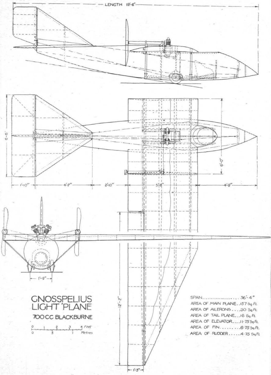
Turning to the general arrangement drawings on p. 293, it will be seen that the Gnosspelius light 'plane has considerable resemblance to a bird in so far as the shape of the wings, body, and tail are concerned. The body, which is of circular cross-section, comes to a point in the nose, and this point, be it noted, is not on the centre line, but is slightly bent down, much as is the head of a bird during flight. We have not the slightest idea whether or not this position has any effect on the resistance. The wing is composed of a parallel central portion with triangular end pieces, or nearly so, the chord of the aileron preventing the entire wing tip from coming quite to a point.
The tail plane is long in relation to its span, and is of triangular plan form. A one-piece elevator is hinged to its trailing edge, and, but for the thinning down of the sloping edges of the tail plane, this is of flat section. The rudder, which is mounted wholly above the tail, is hinged to a triangular fin. The ailerons are of considerable size, each being over 12 ft. long, and of high aspect ratio. Of exposed undercarriage there is practically none, the only projections being less than one-half of two small Palmer wheels.
Having indicated the main aerodynamical features of the design, we may turn to the constructional side. The body is a streamline structure, built very much like a boat, with "hoops" or frames of rock elm and a planking of spruce about 1/16 in. thick. Here and there, where local considerations demand, this main structure is reinforced by extra members. For instance, in the neighbourhood of the cockpit, and under the points of attachment of the wing spars, light spruce frames, forming rectangles inside the circular section, are used for transmitting localised stresses over a larger area, and stout longitudinal members, two inside and two outside, bolted through, serve as supports for the undercarriage and - in the case of the outer ones - as skids when the rubbers stretch sufficiently to let the body itself touch the ground. There is no tail skid, but a sort of keel runs along a portion of the bottom, and on the outside is a metal rubbing strip protecting the planking. The two wheels project through holes cut in the planking, and rather less than half of their diameter is exposed.
The pilot is placed forward of the wing, with his head and shoulders occupying a space cut out in the leading edge. Thus his view is to all intents and purposes unrestricted in any direction that matters, while the fact that the machine is a twin-screw "pusher" relieves him of any slipstream. The only thing that might detract from his perfect happiness is the thought that the engine - not a very big one, it is true - is above and behind him. The controls are of usual type, and do not appear to call for special comment.
Mention has already been made of the fact that the wing section employed is of fairly deep camber, although not of great thickness. One result of this is that it would have been almost impossible to obtain sufficient torsional stiffness with the usual two-spar construction. Consequently Major Gnosspelius decided to employ four spars, and so to design his ribs that any deflection of any one spar should be transmitted to the other three. The spars themselves are of the box type, with spruce flanges and three-ply walls. The ribs are of lattice construction, with double flange strips, in between which are passed the ends of the lattice bars, tacked and glued in place. To be quite accurate, it should, perhaps, be said that the ribs are N-girders rather than lattices, as the compression members are vertical. However, the form should be evident from our sketches.
Apart from its unusual plan form and deep lower camber, the wing section employed in the Gnosspelius light 'plane is of interest in having on the upper surface, coincident with the maximum ordinate, a small step, not unlike the step of a flying boat. The precise aerodynamic action of this step, which runs the whole span of the wing, is not known, but it has been found to increase the efficiency considerably. Whether or not it acts in a manner somewhat similar to the Howard Wright double aerofoil we cannot say, but from the fact that the latter consists of two curves, while the former is a rectangular step, it would appear that, although increased efficiency is the result in both cases, the manner of obtaining it is different. The very fact that any effect at all is noticeable is of interest, and goes to show that there may still be surprises in store for us in the matter of wing sections.
The wing is built up of three sections, a centre section of about 6 ft. span, and two end sections. The joints in the spars are made by fish-plates and long vertical bolts. The latter are of special shape, and incorporate a flat taper at their lower end in order to provide means for drawing together the two spar ends. The shape of these bolts is shown in one of our sketches. For transport along a road, or for storage in a small shed, the end sections can thus be removed by undoing eight bolts. As the ailerons are operated by long tubes having dog clutches incorporated at the joint in the wing, removal of the end sections does not necessitate interfering with the aileron controls. When replacing the end sections of the wing it is, of course, necessary to see that the control-stick is central and the ailerons flush with the rest of the wing. The dog clutches will then engage, and when the wing is bolted up the two tubes cannot slide apart.
Attachment of the centre section to the fuselage is by means of eight long U-bolts, which are dropped down over the spars, and whose ends are passed through holes in the gunwales on the body and secured there by nuts. Owing partly to the relatively small width between gunwales, and partly to the thin wing section employed, it has not been found advisable to make the wing a pure cantilever. The external bracing has, however, been reduced to two struts on each side. As the function of these struts is mainly to help the wing in resisting torsion, they are attached to front and rear spars respectively, the second and third spars transmitting their load via the ribs at this point. The manner of forming these lift struts and their attachments is interesting. Instead of the struts running to heavy fittings on the body, they run right across underneath the "keel," being flattened for the whole distance over which they are in contact with the planking. In order to lighten them they have had pieces cut out over this portion, only the two edges of the flattened tubes being left. The very light fitting locating the tubes on the planking is shown in a sketch.
The 700 c.c. Blackburne engine is mounted in the centre-section of the wing. This position has been chosen for several reasons. To begin with, it is, we believe, intended to use the machine both as a glider and as a light 'plane. In order that this might be possible it was necessary so to place the pilot and engine that the machine would trim correctly whether the engine was on board or not. Consequently the pilot was placed ahead of the wing, in which position he balances the rest of the machine, while putting the engine in the centre-section merely adds weight, but does not cause the total centre of gravity to shift. The engine being air-cooled, it was not possible to place it inside the body, and, although it is thought possible that the projecting cylinders on the centre-section may have a certain amount of adverse effect on the flow of air over the wing, it was decided to try the experiment.
Two pusher airscrews are placed out on the wings, and are driven by two chains, a certain amount of reduction (about 2/3) being used. Each propeller is mounted on a shaft, which is in turn carried in ball bearings in the ends of a large diameter tube, as shown in a sketch. The ball bearings are mounted excentrically in the ends of the tube, so that chain adjustment may be effected by simply twisting the tubular casing around the propeller shafts. The tubes themselves are carried in simple fittings on top of the wing spars, the details being indicated in the sketch. Where the chains pass inside the wing they are enclosed in fibre tube guards.
As already mentioned, the tail is wholly above the top of the body, and forms a unit attached by U-bolts and flat straps to the boat structure. The elevator and rudder kingposts are simple sheet steel fittings, and the fin post is slightly braced by short tubular struts to the tail plane spar. Constructionally the tail is similar to the wing. All control cables pass inside the fuselage, and as there is no transverse bracing they are easily visible for their whole length, as well as reasonably easy to get at for repairs.
The wheel track is narrow, about 1 ft. 9 ins., but even if the machine should lean over until a wing tip touched, the propellers would still be well clear of the ground. It is becoming increasingly evident that on this type of machine a narrow track is quite satisfactory, and, as a matter of fact, the wheels are probably really only required for taking-off. It seems probable that it might be quite feasible to land on the belly of the fuselage, as the machine would have come practically to a standstill before a wing tip touched.
With reference to performance, etc., it is expected that the Gnosspelius light 'plane will weigh about 530 lbs., which figure includes petrol for about two hours' flying. As the wing area is 157 sq. ft., the wing loading will be approximately 3-4 lbs./sq. ft., and the landing speed approximately 30 m.p.h. A maximum speed of about 70 m.p.h. will probably be attained, and a very economical cruising speed of about 45 m.p.h., when the mileage per gallon of fuel should be very good indeed. From the model tests it appears that the minimum power required for horizontal flight is in the neighbourhood of 3 b.h.p. The climb should be good, probably between 400 and 500 ft./min., and as the speed at which the best climb occurs is low, the climbing anojc should be excellent.
The machine is fitted with specially light glider instruments of Smith manufacture, such as air speed indicator reading from 10 to 80 m.p.h, revolution indicator, aneriod, and oil pressure gauges.
- Flight, May 1923
THE GNOSSPELIUS LIGHT 'PLANE
Фотографии

-

Aeroplane Monthly 1979-03 / C.Barnes - Gnosspelius Gull /British pre-war ultralights/
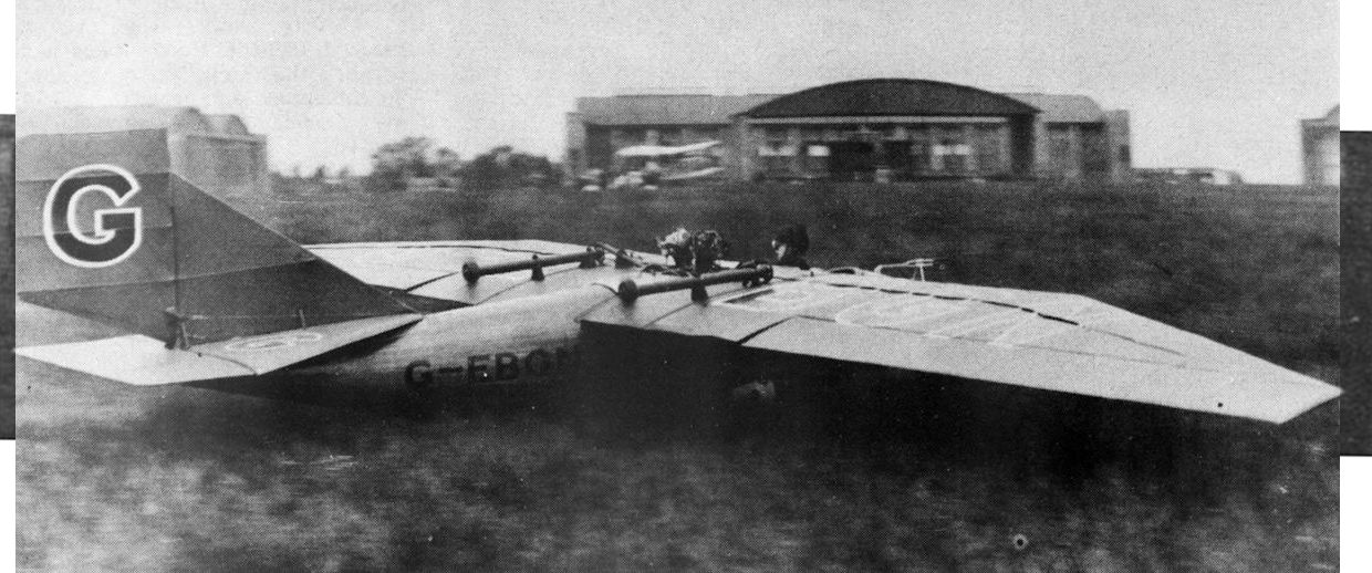
Регистрационный номер: G-EBGN [2] THE GNOSSPELIUS "GULL" TAKING OFF: The unconcerned attitude of the pilot will be observed, indicating the easy handling of the machine
The first Gull, G-EBGN, taking off from Lympne in June 1923. The pilot doesn't seem to be looking where he is going. -

Aeroplane Monthly 1979-03 / C.Barnes - Gnosspelius Gull /British pre-war ultralights/
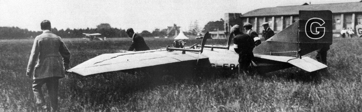
Регистрационный номер: G-EBGN [2] THE GNOSSPELIUS "GULL": This photograph shows the machine being brought out for a flight. Note the long grass on Lympne aerodrome.
Long grass was a great handicap for ultra lights. This picture was taken during the Grosvenor Cup Race at Lympne on June 23, 1923. -

Aeroplane Monthly 1979-03 / C.Barnes - Gnosspelius Gull /British pre-war ultralights/
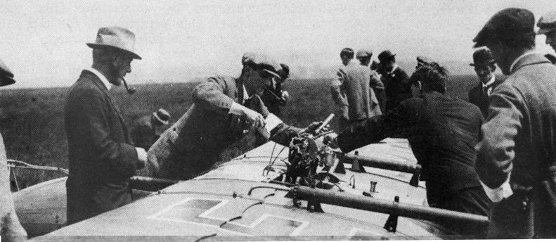
ATTENDING TO THE BLACKBURNE ENGINE: This photograph gives a good idea of the engine mounting and chain transmission to the twin pusher propellers. On the left is seen Major Gnosspelius, the designer of the "Gull."
Maj Gnosspelius, on the left, watches as his Gull's little two-cylinder vee Blackburne motor-cycle engine is tended. -

Aeroplane Monthly 1979-03 / C.Barnes - Gnosspelius Gull /British pre-war ultralights/
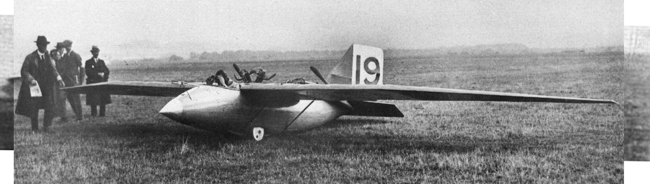
At Lympne: No.19, the Gnosspelius "Gull," coming in after a flight.
The protruding cylinders, semi-faired undercarriage and nose-mounted pitot head are well shown in this photograph. -

Aeroplane Monthly 1979-03 / C.Barnes - Gnosspelius Gull /British pre-war ultralights/
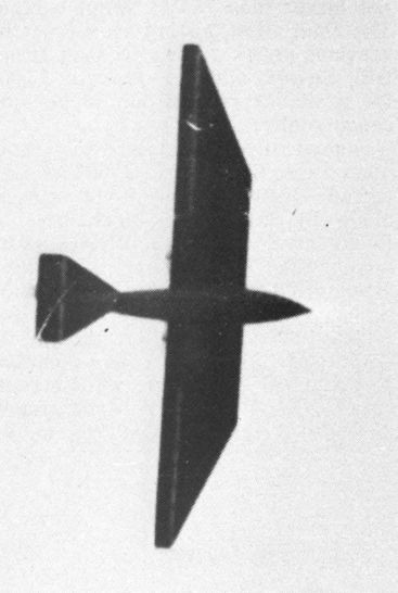
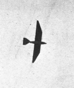
This plan view of the Gull in flight emphasises the angular cut to its wings and tailplane.
-

Flight 1923-10 / Flight
Plan view from below of the Gnosspelius "Gull" flying over Lympne aerodrome.
-

Flight 1923-05 / Flight
The Gnosspelius light 'plane: Three-quarter front view.
-

Flight 1923-05 / Flight
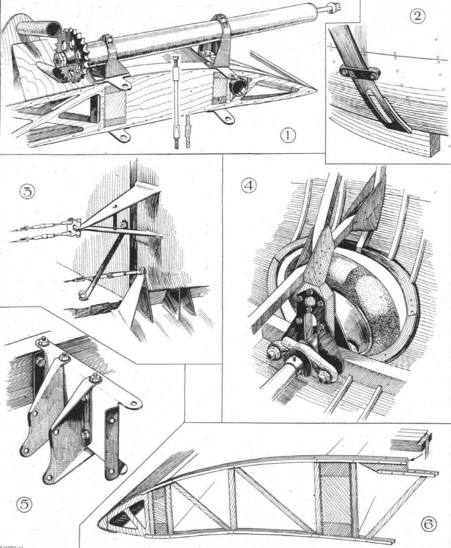
SOME CONSTRUCTIONAL DETAILS OF THE GNOSSPELIUS LIGHT 'PLANE: 1. Mounting of one of the propeller shafts. The shafts are mounted eccentrically in their tubes, thus providing chain adjustment. Note the taper bolt securing wings to centre-section. 2. The lift struts are flattened out and passed under the fuselage. 3. The rudder and elevator cranks are of sheet steel. Note the short tubular strut which braces the fin to the tail plane spar. 4. The wheels of the undercarriage are partly enclosed in the fuselage, a portion of them projecting through an opening cut in the planking. 5. One side of the very simple Duralumin engine bearer, which allows of easy removal of the engine from the centre-section. 6. A typical rib, showing how the "step" is formed.
-

Flight 1923-05 / Flight
Gnosspelius Light 'Plane 700cc Blackburne

- Фотографии