

 Wiki
Wiki 
Варианты
- Boulton Paul - Bodmin / P.12 - 1922 - Великобритания
- Boulton Paul - P.15 Bolton / P.25 Bugle - 1922 - Великобритания
Flight, August 1923
THE BOULTON AND PAUL "BODMIN”
An Exceptionally Interesting British All-Metal Machine
IT is now several years since Boulton and Paul, Ltd., of Norwich, decided, as a result of very extensive experimental research work on metal construction, to specialise on all-metal aircraft, and since that decision was taken several different types of all-metal machines have been produced. As, however, these were built for the Air Ministry, it has not been permissible to refer to them in detail, and all that it has hitherto been possible to give in FLIGHT is external views of some of the types. The consequence has been that far less has become generally known about the really wonderful work being carried out by this firm than the character of the work merits. It is, therefore, with considerable satisfaction that we are able this week to give the first detailed illustrated description of a modern Boulton and Paul all-metal machine, the Air Ministry restrictions having been withdrawn as far as this particular type, the P.12, or "Bodmin," is concerned.
The Boulton and Paul "Bodmin" is of quite exceptional interest to the student of aeronautics, partly on account of its construction, but also because the design incorporates the unusual feature of twin engines placed in the fuselage, with transmission drive to propellers placed on the wings. The "Bodmin," or P.12, to give the machine its proper series number, was designed to an Air Ministry specification calling for central placing of the engines. It is not permissible to state for what particular purpose the machine is required, nor in which locality it is likely to be used, but the main object aimed at has been reliability - not merely reasonably good reliability, but the nearest approach to absolute reliability which, at the moment, it is humanly possible to provide. Consequently the whole power plant installation has been planned with this object in view, and other considerations, such as extra long range and great carrying capacity, have been given second place.
It will readily be understood that, however the problem is attacked, a machine with central engines and propellers on the wings must of necessity be heavier than one in which the engines are placed on the wings. Not only is there the extra weight of the transmission gear, but the fact that the engines are centrally placed increases the load on the wings, which, therefore, have to be built stronger, i.e., heavier, than in the ordinary twin-engined biplane with the engines on the wings. When, therefore, Boulton and Pauls have succeeded in building a machine of this type, in which there is still a reasonably large proportion of useful load, this is an achievement which has been rendered possible mainly by virtue of the all-metal construction. In his paper before the Royal Aeronautical Society, Mr. J. D. North, chief engineer of Boulton and Paul, Ltd., expressed the opinion that metal construction would ultimately afford a means of saving weight, and that already something like 20 per cent, of the structure weight could be saved by scientific metal construction. We believe that, as a matter of fact, the saving effected in the case of the "Bodmin" is of this order, and as the machine is a fairly large one, it will be realised that the effect on the useful load is very considerable. Thus, apart from the questions of rapid production, durability, fire-proof qualities, etc., it would seem to have been demonstrated that the employment of high-tensile steels, if skilfully used, can lead to weight savings which, on the one hand, may render possible the production of a type that would not otherwise be a practical proposition, and, on the other, will increase the useful load or the performance, according to which is the more desired.
As it is mainly the metal construction which has rendered the other feature of the "Bodmin" possible, i.e., the central engine placing, it seems well to devote a certain amount of space to a more detailed reference to the methods of metal construction evolved by Mr. North and his staff of skilled specialists.
With very few exceptions, all parts that are normally made of wood - such as spars, ribs, struts, longerons, etc. - are made, in the Boulton and Paul "Bodmin," of high-tensile steel sheet, rolled, drawn or stamped to the section required. All joints in these built-up sections are made by riveting, no welding being employed. In many places the more usual drawn steel tubes have been replaced by circular section members, manufactured from the flat sheet by processes specially evolved - and patented - by Boulton and Paul, Ltd. In this manner tubes with walls much thinner than could be produced in the ordinary way are made possible, with the result that, as the material is high-tensile steel, a very great reduction in weight can be effected.
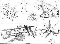
To take first the item which formed, probably, the first subject for metal experimental construction, the wing spars are built up as shown in one of our sketches. The sides are formed of "hour-glass" sections, with the flanges turned over, and into the recesses thus formed the edges of the top and bottom strips are passed, the whole being riveted together with very small rivets (probably in the neighbourhood of 1/16 in. diameter). The spar sides are steadied laterally by short lengths of tube, having a crinkle on the inside of the walls and with their outer edge turned over, thus locking the walls. The top and bottom flange strips are of different sections, according to where they occur. Thus, in the main spars they are rolled to a form of trefoil section, while in the tail plane spars the top and bottom flange strips are simple semi-circles. Where fittings occur the spar walls are reinforced by extra plates riveted to the outside.
The ribs of main planes and tail plane are built up of channel section flanges and struts, braced by U-section diagonal members riveted to the flanges. The internal drag bracing struts are circular tubes, and the means of attaching them to the spars is interesting. Short lengths of tube are built into the spar walls permanently, and on the rear face of the front spar and the front face of the rear spar these short tubes end in a socket carried on a vertical steel plate. The compression struts themselves have similar fittings, and as the plates of strut and fitting are bolted together it is possible to remove a drag bracing strut without interfering with the rest of the wing.
The inter-plane struts, which are in the form of two D-section struts joined back to back by a channel section lacing similar to the wing ribs, are attached, not direct to the wing spars, but to the drag bracing compression struts, so that no torsion is transmitted to the spars. In the case of the tail plane struts a somewhat similar arrangement is followed, with the result that on the rear spar of the tail plane the strut runs behind the spar and is attached to a horizontal compression tube inside joining front and rear spars.
The fuselage longerons are of even more remarkable design than the wing spars. They are rolled from the sheet, and are in two parts, the outer and larger of which resembles in section the Greek letter Omega. The smaller completes the approximately circular section of the finished longeron, and both parts have their edges flanged over and joined together by riveting. One of our sketches shows such a longeron, and also the fuselage fittings, which latter are of the simplest form, consisting merely of flat plates bent through a right angle and having small stiffeners riveted into the angle, from which the eye-bolt for the bracing wire is supported. The inner portion of the longeron is, of course, cut away where the fittings occur, as shown in the sketch.
The fuselage struts are tubes formed from the flat sheet, the edges being turned inwards and the resulting tube being prevented from opening by bands placed around it at intervals of 6 ins. or so.
In a description of a particular machine it is impossible to do more than give a brief outline of the constructional methods employed, but it is hoped that sufficient has been said to indicate the general principles upon which the Boulton and Paul forms of all-metal construction are based. In detail individual members vary in the different types of machines, but the particulars given above apply broadly to all Boulton and Paul types, although research and experiments are being carried out constantly, and modifications introduced as a result of experience gained. It will be realised that such work is necessarily costly, but it will be seen that the results obtained are such as to already indicate the correctness of the views of those to whose far-seeing and bold policy of specialising on all-metal construction Boulton and Paul's present position in the very front rank is due. One can but express the hope that future developments will be such that commercially the firm will reap the benefit to which their technical groundwork has entitled them.
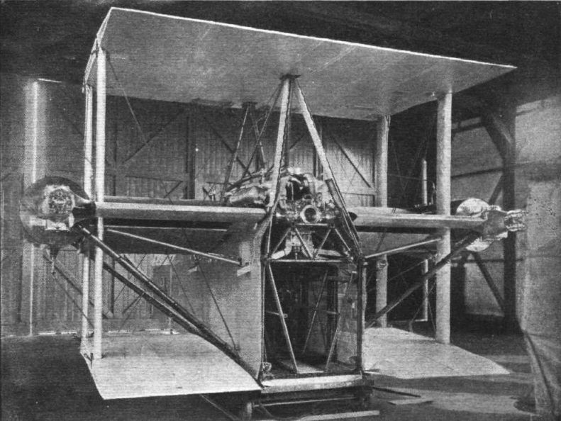
Having outlined the salient features of all-metal construction as carried out at Norwich, we will turn to the general design of the "Bodmin," and more particularly to the feature which forms the raison d'etre of the design, the central engine placing. The machine is a biplane of normal Boulton and Paul lines as regards its wings and fuselage. The two Napier "Lion" engines are, however, placed in, or rather on, the fuselage and drive four airscrews placed some distance out. The two engines are mounted above the fuselage top longerons, leaving the whole of the fuselage space proper free for the engineers to walk along in order to attend to the engines. Between the two engines a small space is left, in which the engineer can stand upright and survey his engines. At this point windows are provided in the fuselage covering, so as to light up the interior, and illumination is further provided by electric lights inside the engine room.
An amazing number of instruments, dials, etc., are to be watched over by the engineer, chiefly on account of the care, that has been taken in planning the installation to ensure that the machine shall not be forced down by engine trouble. Thus there are six separate petrol tanks, so arranged that any one can be shut off should it become holed by shot or damaged in any way. The radiators are in six separate sections, any or all of which can be shut off so as to reduce the amount of water lost owing to a leak or puncture to that contained in one cell. All this interconnection naturally means a considerable amount of piping, etc., and at first sight it seems impossible that one man could look after all the revs, counters, thermometers, oil-pressure gauges, taps, etc. Probably, however, an engineer who has once become familiar with the location of the various items would have no difficulty in keeping an eye on everything.
The propellers, as already stated, are mounted some distance out, between the wings. The two front ones are tractors, and run in opposite directions, the port being of right-hand and the starboard of left-hand pitch. The pushers, which are four-bladers, run in opposite direction to the tractors in front of them, i.e., the starboard one is right-hand and the port one left-hand, and are of smaller diameter than the two-bladed tractor screws. The drive is by long shafts and bevel gears, the whole transmission being designed and constructed by Napiers.
In connection with the mounting of the propellers it is of interest to note that the structure carrying the shafts, gears, and propellers is entirely independent of the wing structure, although superficially it might appear to be part thereof. Each shaft runs out from the engines horizontally, and is supported at its outer end by a strut sloping up from the lower longerons of the fuselage. Cable bracing in the plane of the sloping struts completes the structure, but in order to relieve the structure of a certain amount of load a cable is run from the forward gear-case to the top longeron at a point in line with the rear diagonal strut. This cable transmits the propeller thrust to the fuselage.
The radiators are placed in front of, and in fact supported from, the driving shafts to the front propellers, and their length is such as to fill completely the gap between fuselage and propeller shaft. In this position, therefore, the radiators are always subjected to the slip stream from the tractor screws, so that the engines can be run when the machine is standing on the ground or taxi-ing. As already mentioned, the radiators are divided each into three sections. These sections, or cells, are all of equal size, so that an element can be removed from any point and inserted at any other. The consequence is that but a single small element is needed as a spare. Each element is provided with piping to a distributor box in the engine room, and taps for inlet and outlet are provided for each element, so that both inflow and outflow can be regulated or completely shut off.
From the upper and lower edges of the radiators fabric-covered streamline casings project aft, but these do not quite meet at their rear edge, leaving a space for the air to escape. In the gap between these two surfaces, some little distance ahead of their trailing edge, are mounted oil radiators which cool the lubricating oil from the bevel gear casings. Placed as they are in the air stream behind the water radiators, the action of these oil coolers is automatic.
The main petrol tanks, of which there are two on each side, are slung on the fore and aft members of the transmission structure. This member is in the form of a beam composed of top and bottom tubes, separated by short tubular struts and braced by wire. The tanks are cylindrical in shape, and in their centre is an opening slightly larger than the beam, so that the tanks can be slipped over the end of the beam. They are then secured in place, fore and aft, by screw-on flanges. Rubber pads are interposed between the beam and the inner walls of the tanks. By undoing the four bolts securing the beam to the gear casings the tanks can be removed very rapidly.
Mounted above the top centre section are another two tanks, one of which is normally used as a gravity tank into which petrol can be pumped from either or all of the four main tanks. The second top tank is not normally in use, but should the gravity tank be holed by a shot the other top tank can be turned on and the gravity tank shut off, so that the loss of petrol is confined to that contained therein. A similar system of inter-connection has been employed in the case of the other tanks, so that it is difficult to see how a complete breakdown of the petrol system could occur. What adds still further to the freedom from any power plant disturbance sufficient to force the machine to come down is the fact that the flying tests have proved that the "Bodmin" is definitely able to fly level on either one of the two "Lion" engines. In this respect this type scores over normal twin-engined machines in that whether one or two engines are running the thrust is always central, as the front engine drives the two tractors and the rear engine the two pushers. Moreover, owing to the fact that screws run in opposite directions, there is no turning moment due to slip stream, and the machine should consequently handle approximately equally well whether gliding or flying on one or both engines.
The undercarriage is of the oleo-pneumatic type, in which the wheels, once the machine is in the air, sink down to the end of their travel, giving approximately 18 ins. of movement when the machine first touches. This naturally provides excellent shock absorption, and the "Bodmin" lands without perceptible shock, and without any tendency to "bounce." The undercarriage "legs" are attached to the front spar of the lower centre-section, giving a very wide wheel track. A pair of smaller wheels is mounted forward of the main ones and prevents the machine from nosing over. By fitting this extra pair of wheels in front it has been possible to place the main wheels slightly farther aft than is usual, thus relieving the tail skid of a great proportion of its load.
Ailerons and tail plane are of the leading-edge-balance type, supported on brackets from the rear face of the rear spars, and in order to reduce air losses past the leading edge, aluminium strips, curved to the same radius as that of the balance, have been bolted to the rear spars. This is indicated in one of our sketches. Needless to say, a trimming tail plane is used, operated by a worm, which in turn is actuated by cables and a wheel in the pilot's cockpit.
Reference has already been made to the engine installation, and it only remains to state that the exhaust pipes are of special form, deep from front to back but narrow in width, and with saw-cuts for the escape of the gases. These pipes are made from stainless steel to avoid scaling, and they are built up without welding, the parts being bolted together.
In an article like this it is scarcely possible to deal adequately with all the features of a machine in which there is so much that is novel and unusual, but it is hoped that in the foregoing no point of vital importance has been omitted. Although the Boulton and Paul "Bodmin" is purely a military machine, it may be supposed that some of the features of the central engine placing, and, of course, practically all of the all-metal constructional details, are applicable to commercial aircraft, and if long-distance air transport by heavier-than-air craft is to become a practical proposition it may well be that the engine-in-the-hull type will have to be seriously studied. In that case also the metal construction should prove its worth, as machines used for such a service would certainly have to fly through wide ranges of changing climatic conditions, which might be found to be so severe as to handicap seriously the wood-cum-metal construction.
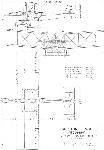
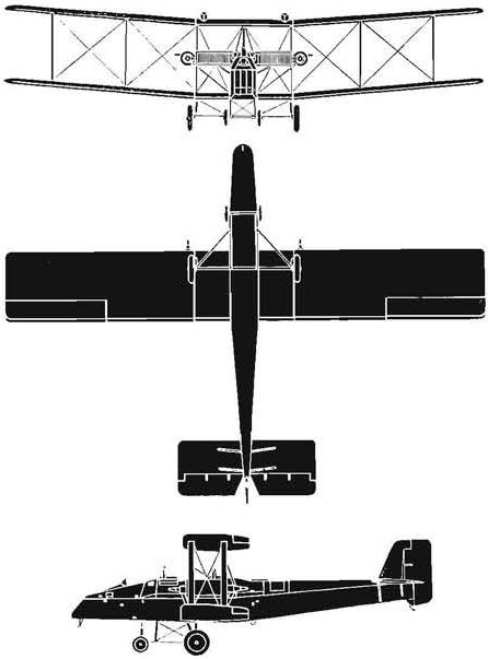
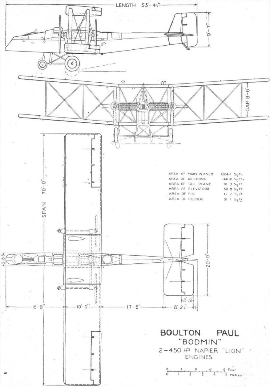
The main characteristics of the Boulton and Paul “Bodmin" are as follows: Length, o.a., 53 ft. 4 1/2 ins.; span, 70 ft. wing area, 1,204-1 sq. ft.; gap, 9 ft. 6 ins.; chord, 10 ft. weight, empty, 7,920 lbs.; petrol (230 gallons), 1,660 lbs. oil (32 gallons), 320 lbs.; crew, 540 lbs.; useful load, 560 lbs.; total loaded weight, 11,000 lbs.; wing loading, 9-1 lbs./sq. ft. power loading, 12-2 lbs./h.p.; speed at ground level, 116 m.p.h.; at 10,000 ft., 112 m.p.h.; at 15,000 ft., 102 m.p.h.; service ceiling, 16,000 ft.; climb to 6,500 ft. in 8-9 mins.; to 10,000 ft. in 16 mins.; to 15,000 ft in 35-5 mins.
- Flight, August 1923
THE BOULTON AND PAUL "BODMIN”
Фотографии

-
Flight 1923-09 / Flight
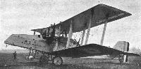
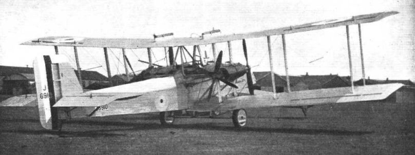
Регистрационный номер: J6910 [4] THE BOULTON AND PAUL "BODMIN": Side view showing small auxiliary front wheels.
-
Air Pictorial 1955-09
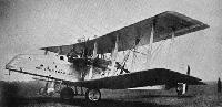
Регистрационный номер: J6910 [4] BOULTON PAUL BODMIN. Designed around official specification 11/20, the Boulton Paul Bodmin "Postal" aircraft was completed in 1922 and bore the type number P.12. Serialled V6910 and V6911 the two prototypes were tested by the Air Ministry. They were unusual in having twin Napier Lion engines mounted in the fuselage, driving pusher and tractor propellors on the inter-plane struts via belt drive. The unstaggered wings were square-cut with marked dihedral on the outer sections. Main undercarriage consisted of two large and two small wheels under centre section and nose respectively, and a skid under the tail. The cockpit was set back under the top wing, while the nose was exceptionally long.
-
Flight 1923-08 / Flight
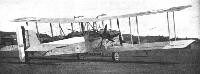
THE BOULTON AND PAUL "BODMIN": This machine has several very interesting features, chief of which Is the central placing of the engines (Napier "Lions") in the fuselage, with drive to four propellers mounted between the planes.
-
Air Enthusiast 2003-11 / A.Brew - Proud heritage
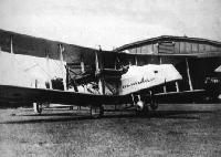
Регистрационный номер: J6910 [4] The first P.12 Bodmin, J6910, showing the radiator and transmission 'fairing' out to the propeller housings.
-
Flight 1925-06 / Flight
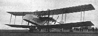
Регистрационный номер: J6910 [4] AN EXPERIMENTAL MACHINE AT THE R.A.F. DISPLAY: The Boulton and Paul "Bodmin" (two 400 h.p. Napier "Lions") with gear transmission.
-

Flight 1923-09 / Flight
THE BOULTON AND PAUL "BODMIN": View of the engine room and transmission.
-

Flight 1923-09 / Flight
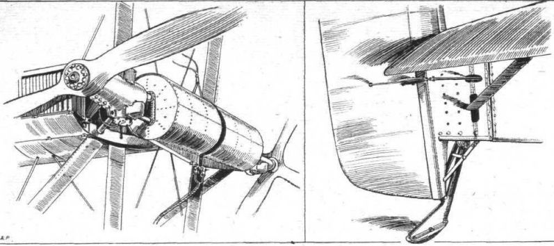
THE BOULTON AND PAUL "BODMIN": On the left, one of the gear casings, the tractor and pusher screws, and two main petrol tanks slung on a tubular braced member. On the right, a view of the tail skid, etc.
-
Flight 1923-09 / Flight
THE BOULTON AND PAUL "BODMIN": Details of tail plane, spar and bracing strut attachment. The elevator has leading edge balance, and is carried on brackets from the rear spar. In the lower left-hand corner is shown the attachment of the tail plane bracing strut to the rear face of the spar. On the right, a typical fuselage fitting and section of longeron.
-
Air Pictorial 1955-09
BOULTON PAUL BODMIN. Data: Manufacturer: Boulton and Paul Ltd. (later Boulton and Paul Aircraft Ltd.). Power: two 450-h.p. Napier Lion engines. Accommodation: four-seat. Dimensions: span 70 ft.; all-up weight 11,000 lb. Performance: maximum speed 116 m.p.h.
-
Flight 1923-09 / Flight
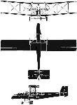
Boulton Paul "Bodmin" 2-450 hp Napier "Lion" Engines


- Фотографии