Flight, October 1931
A NEW DORNIER MACHINE
The Do-K Twin-Tandem Engined Monoplane
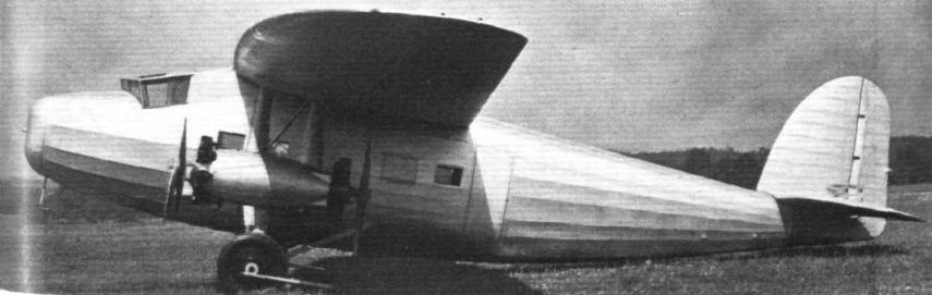
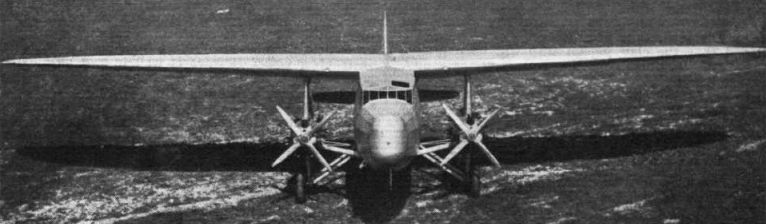
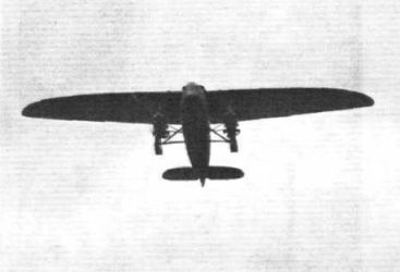
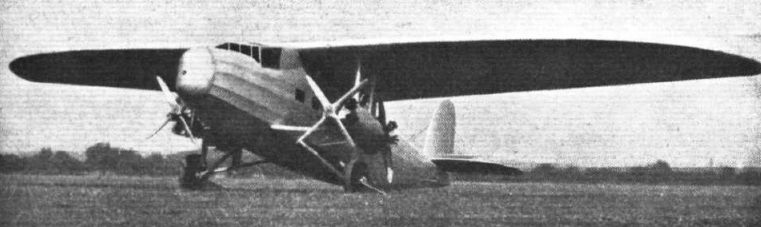
IN his latest type Dr. Claudius Dornier has departed considerably from what has come to be regarded as standard Dornier practice. This may be, and probably is, due to the fact that for once the machine in question is a landplane, whereas of recent years by far the greater part of Dornier productions have been monoplane flying-boats, but the structural details also differ considerably. The Do-K, as the latest type is called, is a four-engined, high-wing monoplane, with the engines arranged in two tandem pairs, and placed a very considerable distance below the wing. In the experimental machine, which is now undergoing the company's test flights at the Lowenthal aerodrome, near Friedrichshafen, the engines are 240 h.p. Walter "Castors." Presumably when the production type is placed on the market other makes of engine of similar power can be substituted.
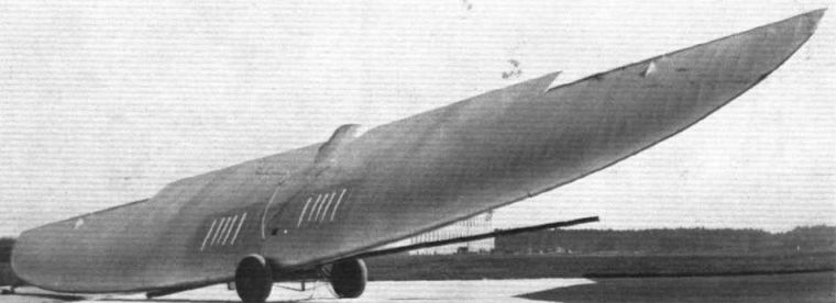
The plan form of the wing of the Do-K shows an approximately straight trailing edge, while the leading edge is of approximately elliptic curvature, with pronounced taper in chord towards the wing tips. The wing is built as a pure cantilever structure.
Of what appears to be very good streamline shape, the fuselage is of oval cross-section, with the monoplane wing attached to the top. In the nose of the fuselage is a luggage compartment. Behind that is the pilot's cockpit, and aft of that again the cabin, which has seating accommodation for 10 passengers.
Although the Do-K is still undergoing tests, certain facts concerning performance, etc., have already emerged. For instance, when flying at 1,000 m. (3,300 ft.) altitude, it was found that with two of the four engines stopped, the rate of climb was still 0.4 m./sec. (79 ft./min., or a little less than the rate of climb corresponding to service ceiling). Presumably this figure was obtained with the machine carrying full load, although this cannot definitely be ascertained at the moment.
The main dimensions and weights of the Do-K are as follow :- Length, 16,5 m. (54 ft. 2 in.); wing span, 25 m. (82 ft.); height, 4,2 m. (13 ft. 9 in.); wing area, 88 m2. (948 sq. ft.); weight, bare, 3 600 kg. (7,925 lb.); tare weight, fully equipped, 4 000 kg. (8,800 lb.); gross flying weight, 6 000 kg. (13,200 lb.); wing loading, 14 lb./sq. ft.; power loading, 13.75 lb./h.p.
At a gross weight of 13,200 lb. the following performances were attained during lest flights :- Maximum speed, 220 km./h. (136.5 m.p.h.); cruising speed, 200 km./h. (124 m.p.h.); ceiling, 6 300 m. (20,650 ft.); ceiling with one engine stopped, 3 800 m. (12,500 ft.).
At a later date we hope to describe this machine in greater detail.
Показать полностьюShow all
Flight, October 1931
The New Dornier Landplane
By EDWIN P. A. HEINZE
ALREADY, in the issue of October 9, FLIGHT was able to give some advance details of the new Dornier machine, the Do-K, which is at present undergoing its approbation tests. Owing to the kindness of the makers, which we duly acknowledge, the writer has received further interesting details of the machine, which give a good idea of the constructional features of the plane.
As our readers will recollect, the machine is an altogether new design, bearing no resemblance to the old Dornier "Merkur" landplane, which had a single engine and could convey six, or at most eight, passengers besides the crew of two. The Do-K has a streamline fuselage of oval section with a cantilever type wing of entirely new form secured on top, and has ample cabin space for ten passengers. The idea of the designers was to create a fast passenger transport machine incorporating a high degree of safety for flying over country offering few possibilities of alighting in cases of emergency, such as the Alps and big deserts. For this reason high aerodynamical efficiency had to be secured, and the power plant had to be subdivided to as great an extent as was compatible with economical working. Four air-cooled Czecho-Slovakian Walter "Castor" engines of 240-h.p. output each were adopted and suspended in couples, one behind the other, beneath the wing right and left of the fuselage. The front engines have been provided with four-bladed wooden tractor screws and the rear with two-bladed pusher screws. With a full flying weight of 13,200 lb. this machine, during its trials, was able to attain a maximum speed of 137 m.p.h., the average touring speed being 125 m.p.h. and the ceiling 20,600 ft. With the same weight and one engine "dead,'' the machine was still able to rise to 12,800 ft., and with two engines stopped it climbed at the rate of 1.3 ft. per second at an altitude of over 3,200 ft. with the same flying weight.
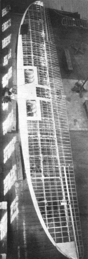
The wing has a span of 82 ft., a maximum chord of 13 ft. 9 in., and a lifting area of 977 sq. ft. To secure low profile height (or wing thickness), which only amounts to 27 1/2 in., it was found advisable to employ three spars instead of the two usually adopted. In this Dr. Dornier has followed the practice that has already proved successful in the Do-X and the recently introduced Do-S, a flying boat with cabin space for 22 passengers, which is a successor of the famous "Superwal" type. The three spars consist each of a top and bottom rail of rolled duralumin of channel section. These rails are trussed by upright and diagonal channels riveted in place, the compression members of which are reduced in weight by a number of holes in the channel beds. The wing has a practically straight rear edge, to which the leading edge sweeps round, and it tapers in thickness towards the tips.
The spars are connected by fourteen main ribs, twelve auxiliary and a large number of forming ribs. The main ribs are constructed in a manner similar to the spars and, like the other ribs, of course, also are made of duralumin. They pass over the top and bottom surfaces of the spars, to which they are secured by short channel sections riveted on. The upright and diagonal bracings likewise consist of channels. The wing panels thus formed by the main ribs and spars are braced horizontally in two planes by crossed wires. The upper channels of the main ribs between the spars being straight, forming ribs of smaller and lighter duralumin channels are superimposed. The lower channels are slightly arched upwards between the spars and for this forming ribs, which give a plane lower surface, had likewise to be employed.
A number of auxiliary spars are formed by relatively small diameter tubes of oval section passing through the joints on the main and auxiliary ribs where the upright and diagonal web channels meet. Over these tubes slipped a number of small pressed plates. Joints are formed by three rivets placed equidistantly around the circumference, with a distance-piece between, and they serve to hold the top and bottom channels of the light forming ribs, which have no web structure of any kind.
The leading edge of the wing is formed by shaped duralumin sheets, and the ailerons, which are constructed like the wing, are arranged in a cut-out in the trailing edge, of which their trailing edges form continuations to the tips. These are rounded and merge into the tip curves of the main wing. The upper and lower surfaces of the ailerons, when in their normal position, are flush with the wing and leave no slot between them and the latter. They are pivoted, however, on their lower sides some distance from their from edge on a number of brackets fixed on the rear spar of the wing. These brackets, when the ailerons are flush with the wing, cannot be seen, as they lie within corresponding recesses or slots in the ailerons, which are not balanced. Both the wing and the ailerons are fabric covered. The ailerons are operated by a rod coming out of the upper wing surface, and which is pivoted to a horn on top of the ailerons. Inside the wing and also for the operation of the tail plane, steel cables are employed in combination with the usual pulleys and bell cranks.
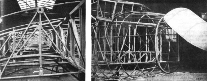
The wing is secured in the normal manner on the fuselage which, with a length of 52 ft. 2 in., has a main framework of steel tubes, around which is arranged a forming framework of duralumin hoops of channel section with flanges turned inwards. The hoops are joined by numerous stringers, also of channel section, which are secured to the hoops by one flange, while the other and outer flange is perforated for the attachment of the fabric covering. The steel tubes are flattened at the ends and slotted. Gusset plates are pressed into these slots, and screw bolts passing through the tubes and plates secure the joints. Only in some points of minor importance are rivets employed. In the, cabin section of the fuselage the steel frame is braced with diagonal tubes. At the sides the outside forming frame comes close to the steel frame, but still the rather small windows in the outer frame are a few inches out from the steel frame, so, when the cabin equipment is complete, they appear inside recesses from the interior. In front of and to the rear of the cabin the steel frame is braced by wire.
While the rear end of the fuselage tapers into a point flattened at the sides, the front end is formed by a large duralumin cap, which is hinged at the top, and, when open, gives access to a spacious luggage hold. Behind this follows the cockpit for the two pilots, whose seats are raised. This cabin is totally enclosed, and the roof superstructure of duralumin merges into the wing top. The roof sections over the pilot's seats slide in guides, and can be pushed back. Access to the cockpit is attained through the passenger cabin, to the rear of which is a lobby, with the entrance on the left and a lavatory on the right side, while behind this a further luggage or goods hold is to be found.
The tail, which is also fabric covered, is situated on top of the fuselage, with the rudder fin standing on the tailplane, which is braced with wires both against the fin and the fuselage. The rudder, extending down the rear edge of the fuselage, requires the elevator to be divided. The latter is balanced by the small typical Dornier compensating planes arranged a few inches above the tailplane.
The engine nacelles are suspended each by two perpendicular faired struts from the wing. These two struts form a rectangular frame, of which the top beam is secured in a shallow recess in the lower wing surface, where two steel eyes are provided to attach it. A diagonal tension rod braces the struts and takes the propeller pull. Two almost horizontal struts connect each engine nacelle with the fuselage. Also with these a diagonal tension rod is used. The engine control rods are located inside the fairing of the upright struts.
The landing wheels are mounted on the apex of two struts, each arranged to form a triangle with the fuselage, on which they are hinged. The spring legs are attached to the bottom of the engine nacelles and incorporate Rheinmetall (Faudi) pneumatic shock absorbers. The wheels are furnished with long mudguards extending at the rear. For the tail support a skid is employed.
Показать полностьюShow all

 Wiki
Wiki