
Описание
 Wiki
Wiki 
Страна : Германия
Год : 1929
Летающая лодка
Трансокеанская летающая лодка с экипажем из пяти человек
Dornier Do X
Летающая лодка Do X, построенная швейцарским филиалом компании "Dornier", базирующимся в Альтенрхейме, на момент своего первого полета, состоявшегося 25 июля 1929 года, была самым большим самолетом в мире. К работам над этой машиной, предназначенной для перевозки 100 пассажиров через Атлантику при уровне комфорта, не уступающем океанским лайнерам, приступили в 1927 году. Цельнометаллический самолет первоначально имел силовую установку из шести пар радиальных двигателей Bristol Jupiter мощностью по 500 л.с. (373 кВт), выпущенных по лицензии фирмой "Siemens". На трех палубах 40-м фюзеляжа Do X размещались отдельные каюты для пассажиров, комната отдыха, курительный салон, ванная, кухня и обеденный салон. В закрытой кабине на летной палубе размещался экипаж, состоявший из двух пилотов, штурмана и радиста. Место бортинженера, на котором были сосредоточены рычаги управления двигателями, размещалось в задней части кабины, так что регулировка тяги представляла собой нетривиальную задачу для пилотов. Кроме того, бортинженер мог обслуживать силовую установку в полете, используя для доступа к ней специальные туннели, расположенные в толстом крыле. Выяснилось, что двигатели "Siemens" не додают мощности, и их заменили изделиями фирмы "Curtiss". Но из-за проблем с охлаждением задние двигатели все равно не могли работать на полных оборотах. Тем не менее впечатляющая грузоподъемность самолета была продемонстрирована в полете, состоявшемся 31 октября 1929 года, когда благодаря "безбилетникам" на борту оказалось 170 человек, на 10 больше максимального количества пассажиров и членов экипажа.
А 2 ноября 1930 года Do X покинул Фридрихсхафен, чтобы совершить перелет в США через Амстердам, Кэлшот (Англия) и Лиссабон. Полет сопровождался различными происшествиями. В Лиссабоне из-за пожара в топливном баке было повреждено крыло, на ремонт которого потребовался месяц. При взлете из Лас-Пальмаса на Канарских островах получил повреждения корпус лодки, что привело к трехмесячной задержке. При следующей попытке самолет максимально облегчили, оставив на берегу часть оборудования и "лишних" членов экипажа. Хотя на большей части маршрута Do X не мог набрать крейсерскую высоту, он благополучно проследовал в Наталь (Бразилия) через Португальскую Гвинею, острова Кабо-Верде и Фернандо-Норона, завершив очередной этап перелета. Затем Do X перелетел в Рио-де-Жанейро, откуда взял курс на США вдоль восточного побережья Южной Америки. Через Вест-Индию и Майами летающая лодка прибыла в Нью-Йорк 27 августа 1931 года. Обратный перелет стартовал 19 мая 1932 года. Через Харбор Грейс, Хорту, Виго и Кэлшот Do X вернулся в Берлин 24 мая 1932 года.
Гигантская летающая лодка вошла в число самолетов, погибших при попадании бомбы в Берлинский музей в годы Второй мировой войны. Были построены еще два экземпляра Do X, оснащенных двигателями Fiat, которые в экспериментальных целях использовались итальянскими ВВС, а затем были пущены на слом.
ТАКТИКО-ТЕХНИЧЕСКИЕ ХАРАКТЕРИСТИКИ
Dornier Do X
Тип: трансокеанская летающая лодка с экипажем из пяти человек
Силовая установка: 12 V-образных поршневых двигателей Curtiss V-1570 Conqueror мощностью по 640 л. с. (477 кВт)
Летные характеристики: максимальная скорость у земли - 210 км/ч; крейсерская скорость на оптимальной высоте - 175 км/ч; потолок 1250 м; дальность полета 2200 км
Масса: пустого 32675 кг; максимальная взлетная 56000 кг
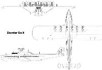
Размеры: размах крыла 48,00 м; длина 40,00 м; высота 10,10 м; площадь крыла 450,00 м1
Описание:
- Dornier Do X
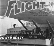
- Flight, June 1929
OLYMPIA AERO SHOW 1929 - Flight, February 1930
THE DORNIER Do. X
Фотографии

-

Flight 1930-02 / Flight
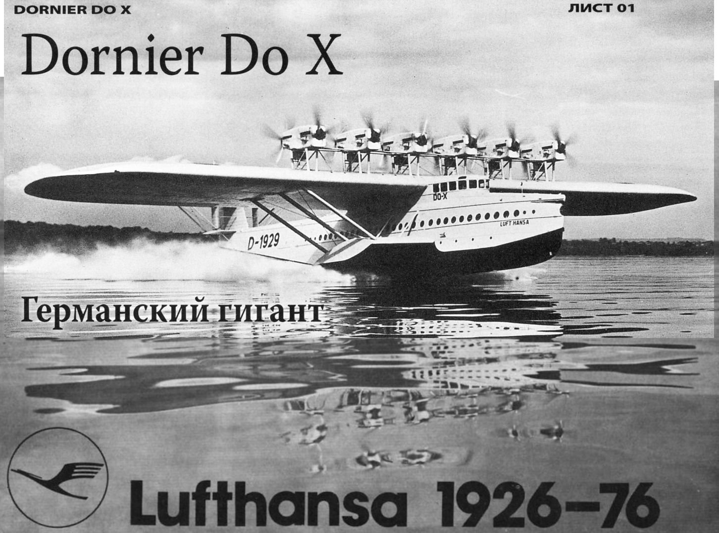
25 июля 1929г.: летающая лодка Dornier Do X впервые взлетела с поверхности озера Бодензее. 21 октября она установила рекорд, совершив полет продолжительностью 1 час со 169 пассажирами и экипажем на борту.
Огромный Do X на этом снимке еще оснащен радиальными двигателями Jupiter. Обратите внимание на обтекатели стоек мотогондол. -

Flight 1929-07 / Flight
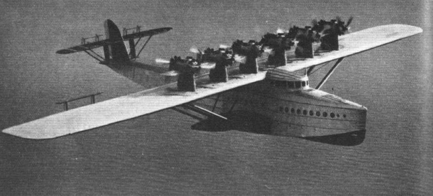
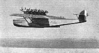
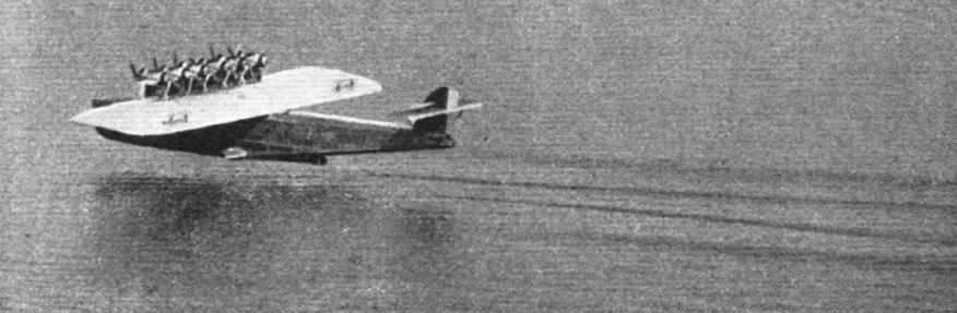
IN FULL FLIGHT: The Dornier Do. X photographed from another aeroplane flying over Lake Constance
-
-

Flight 1929-07 / Flight
THE FIRST FLIGHT: The Dornier Do. X leaving the water for the first time.
-

Flight 1929-07 / Flight
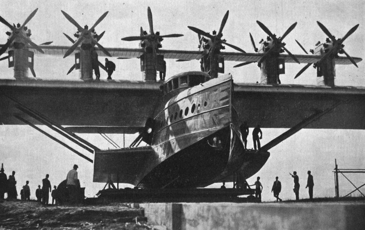
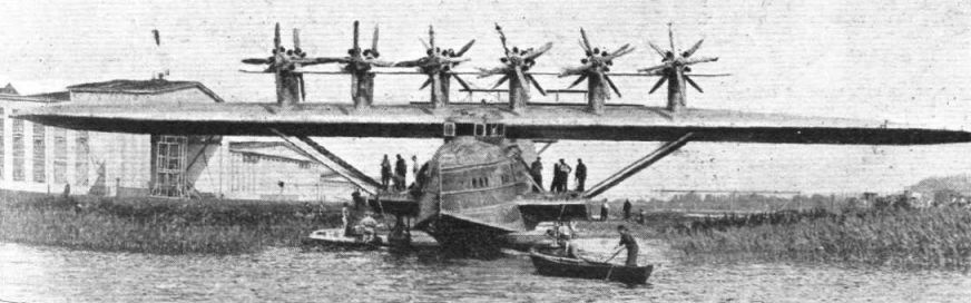
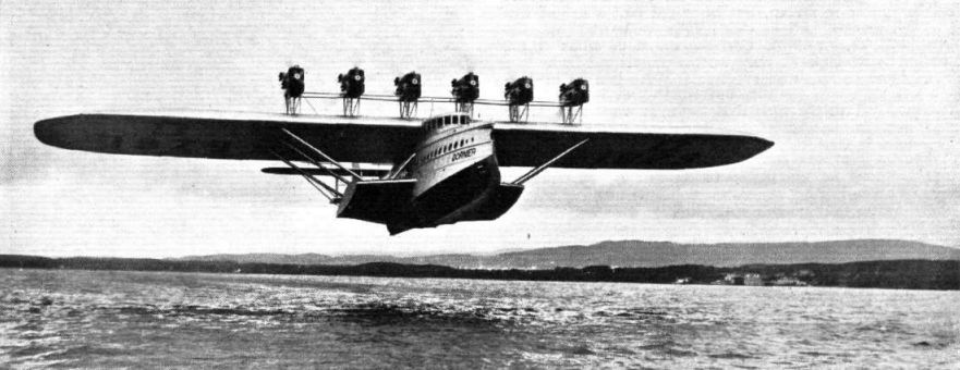
LAUNCHING THE WORLD'S LARGEST FLYING-BOAT: The 12-engined Dornier Do. X leaving its slipway. Scale is given to the picture by the people standing on the lower wing roots.
-

-

Flight 1929-09 / Flight Advertisements
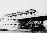
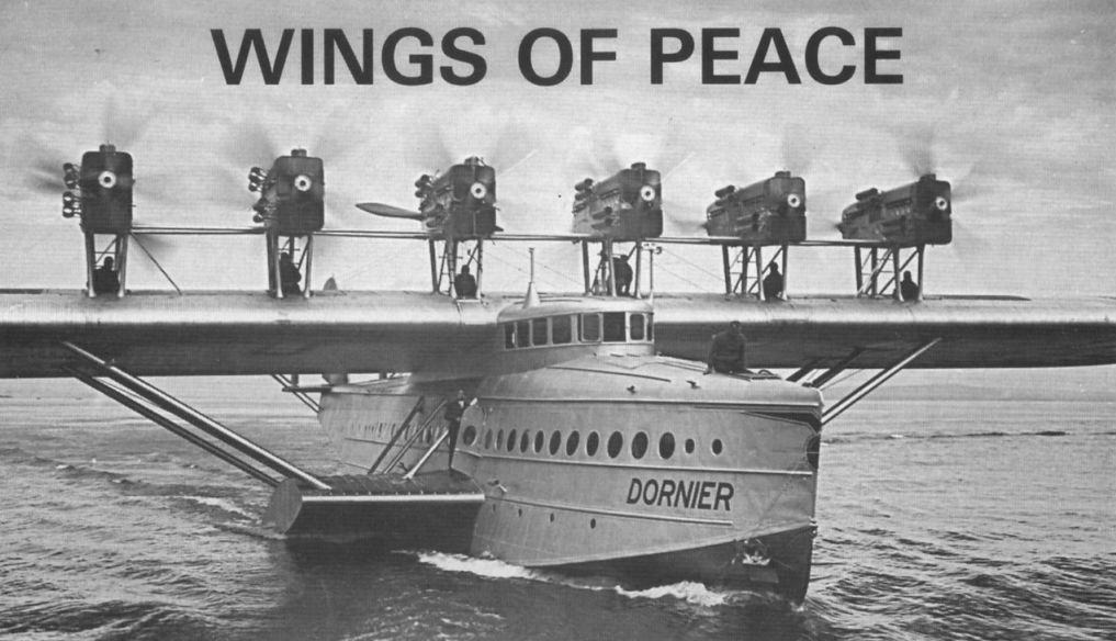
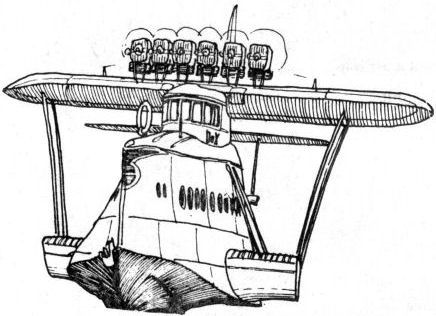
Моторы Bristol Jupiter были установлены попарно в обтекаемых гондолах, соединенных между собой вспомогательной горизонтальной поверхностью. Техническое обслуживание моторов могло производиться прямо в полете.
Dornier Flying Ship Do.X fitted with 12/525 h.p. Siemens-Jupiter Engines at Altenrhein before launching. -

Flight 1929-07 / Flight
JUST BEFORE THE LAUNCH: The Dornier Do. X on the slipway. Note the tandem arrangement of the "Jupiter" engines.
-

Aeroplane Monthly 1989-01 / ??? - Do X portfolio
The arrangement of the Jupiter engines, with auxiliary wing.
-

Aeroplane Monthly 1987-10 / J.Stroud - Wings of Peace
The Do X in its assembly hall at Altenrhein. The small propeller may have been used for engine tests.
-

Flight 1929-07 / Flight
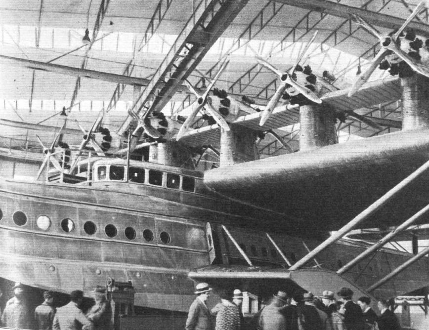
THE GIANT OF THE AIR: Unable to exhibit the actual machine, the Dornier firm is showing a scale model of the Do.X. This photograph, taken in the Dornier Works, shows the actual machine, and gives an excellent idea of the size.
-

Aeroplane Monthly 1989-01 / ??? - Do X portfolio
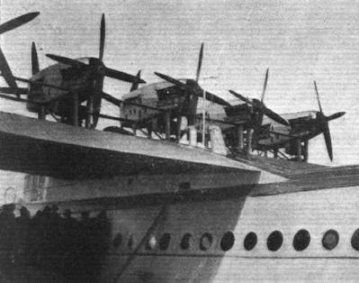
After re-engining. The two outermost starboard pairs of Curtiss Conquerors. The corrugated skin of the leading edge may clearly be seen in these views.
-

Aeroplane Monthly 1983-09 / P.Capon - Capon's Corner
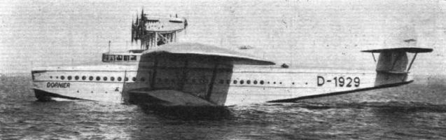
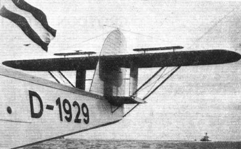
Регистрационный номер: D-1929 [16] -

-
Flight 1930-08 / Flight
Регистрационный номер: D-1929 [16] THE Do. X. is now afloat again and has 12 Curtiss Conqueror type G.V. 15 per cent. 600 H.P. water-cooled engines installed. These are geared and mounted, as were the Jupiter engines, in six tandem nacelles.
-

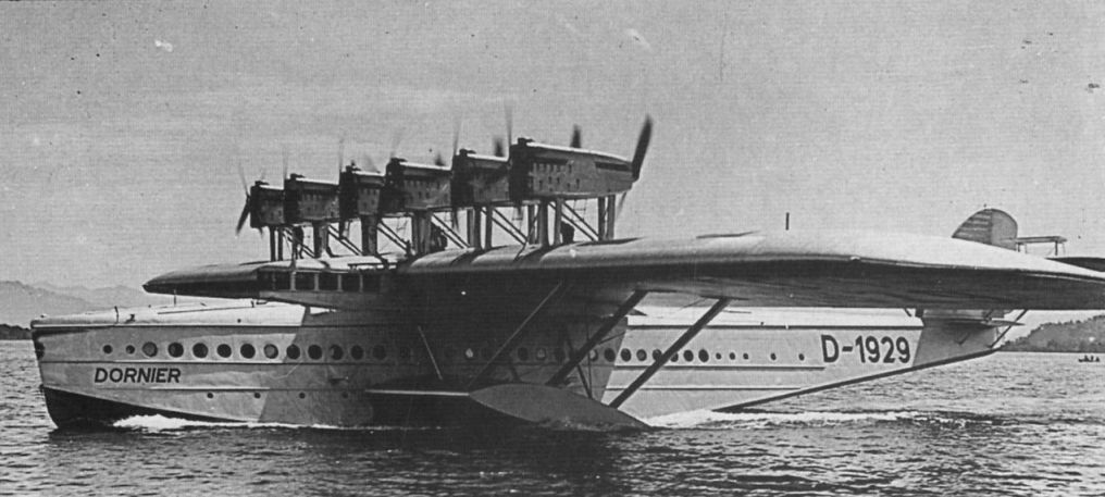
Aeroplane Monthly 1987-10 / J.Stroud - Wings of Peace
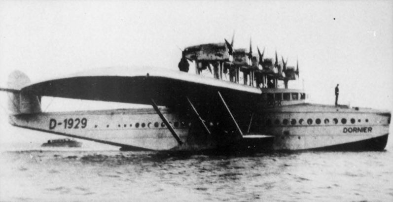
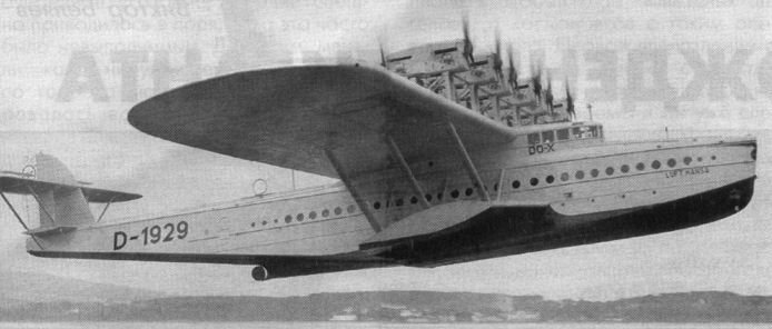
Регистрационный номер: D-1929 [16] The Do X after being re-engined with two-bladed propellers on the rear engines.
-
Air Enthusiast 1972-06 / L.Coombs - Front-office evolution (2)
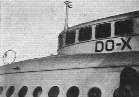
Регистрационный номер: D-1929 [16] The "bridge" of the 12-engined Dornier Do X flying-boat with its bay window followed the style adopted by several German WW I bombers.
-
-

-

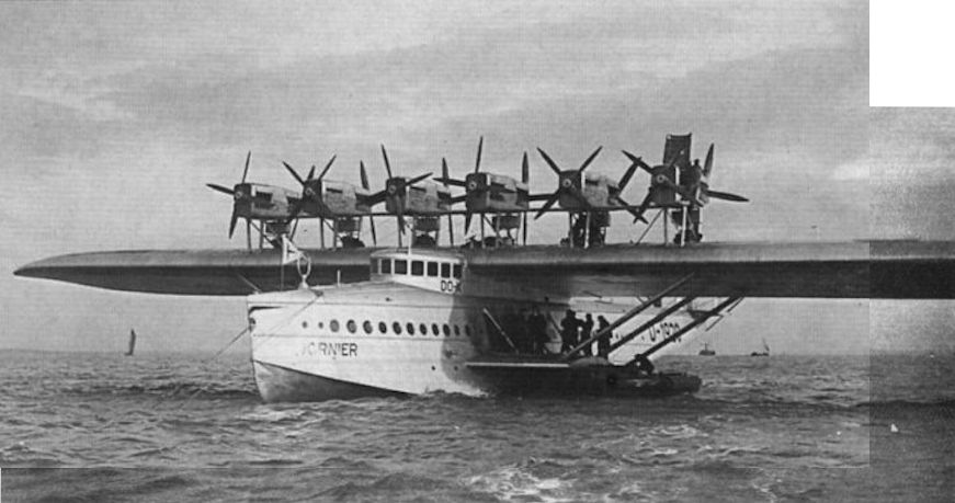
Aeroplane Monthly 1987-10 / J.Stroud - Wings of Peace
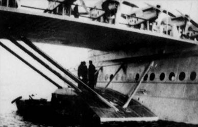
CURIOSITY FOR THE CURIOUS: Visitors - of which there were many - going aboard the Do.X at Calshot on its way to South America.
-
Aeroplane Monthly 2001-06 / R.Riding - 2,974 weeks /The Aeroplane 90th anniversary/
Регистрационный номер: D-1929 [16] An unusual visitor to the UK reported by The Aeroplane was the massive Dornier Do-X flying-boat, seen here at Calshot in November 1930 en route from Germany to America. Powered by twelve 600 h.p. Curtiss Conqueror engines, D-1929 arrived with a crew of 15 and with 23 passengers on board, including Dr and Mrs Dornier.
-
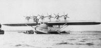
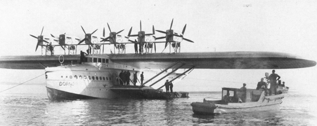
Aeroplane Monthly 1983-09 / P.Capon - Capon's Corner
View of the prototype Dornier Do X flying boat taken during its visit to Calshot on November 10-15, 1930. D-1929 was powered by twelve 600 h.p. Curtiss Conqueror engines and first flew in July 1929 from Bodensee. On leaving Calshot the Do X flew on to Lisbon where the wing was damaged by fire.
-

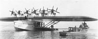
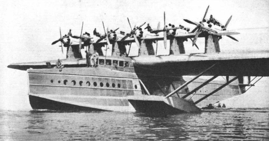
Flight 1932-05 / Flight
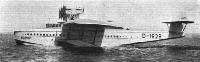
Регистрационный номер: D-1929 [16] THE ATLANTIC CIRCUMNAVIGATED: Two views of the Dornier Do.X moored off Calshot. These pictures give a good idea of the height of the propellers above the water line, where they are well protected against spray. The use of the lower wing stumps as boarding platforms is also well brought out.
-

Aeroplane Monthly 1989-01 / ??? - Do X portfolio
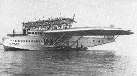
Регистрационный номер: D-1929 [16] Do X на пике славы - летающая лодка прибыла в Нью-Йорк, где ее встречала огромная толпа. Самолет оставался в нью-йоркской гавани на протяжении зимы 1931/32 годов, в ожидании благоприятных погодных условий для возвращения в Германию.
The Do X on arrival in New York in August 1931. -

Авиация и Космонавтика 2024-01 / Ю.Кузьмин - Гидросамолеты. Фаза антиквариата
Регистрационный номер: D-1929 [16] Среди гидросамолетов встречались и настоящие гиганты, такие как Дорнье Do-X (1929 г.)
-

-

-

Aeroplane Monthly 1976-04 / H.Seabrook-Smith - Lufthansa 1926-76 (1)
Регистрационный номер: D-1929 [16] После своего триумфального возвращения в Германию из США летающая лодка Do X совершила ряд демонстрационных полетов по стране. Затем самолет передали авиационному музею в Берлине.
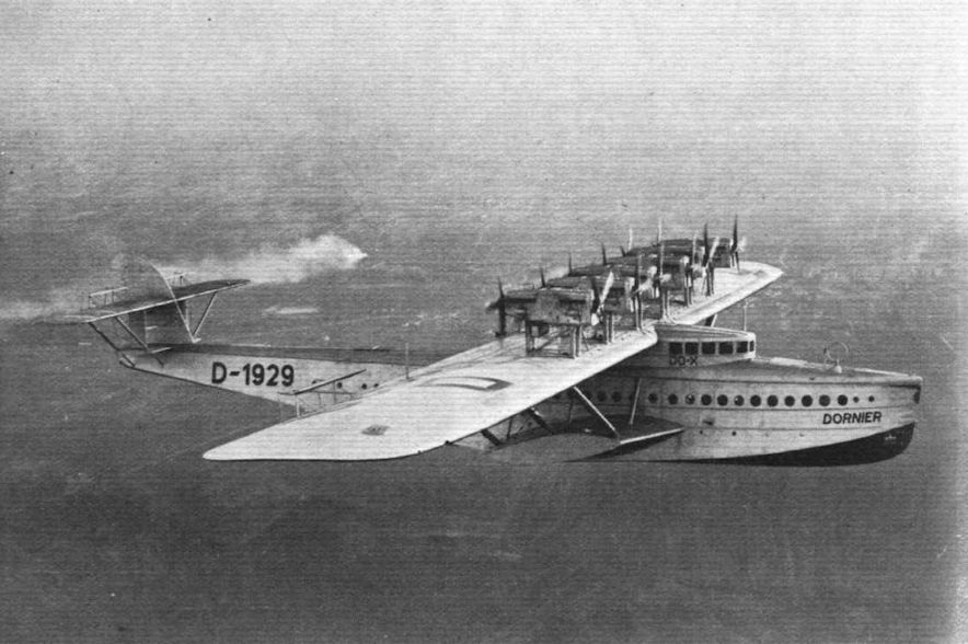
A giant of the past. The prototype Dornier Do-X, D-1929, seen during its short spell with Lufthansa in the 1930s. It has 12 600 h.p. Curtiss Conqueror engines, which replaced the original Siemens Jupiters. -

Авиация и Космонавтика 2005-03 / В.Беляев - A380: Рождение гиганта
Регистрационный номер: D-1929 [16] Дорнье Do-X
-
-

Авиация и Космонавтика 2025-11 / А.Пухлов - Советская гражданская авиация довоенного периода 1920-1941гг. (5)
Регистрационный номер: D-1929 [16] Dornier Do X совершил первый полет в 1929 году, неся на борту 169 пассажиров, что являлось абсолютным рекордом для первой половины XX века
-

Aeroplane Monthly 1989-01 / ??? - Do X portfolio
Регистрационный номер: D-1929 [16] Do X D-1929 over the Rhine en route for Amsterdam on the first stage of her flight to America, via England and Lisbon, in November 1930.
-

Flight 1930-11 / Flight
Регистрационный номер: D-1929 [16] EN ROUTE FOR ENGLAND: An aerial view showing the Dornier Do.X flying over the Rhine en route for Amsterdam on the first stage of her flight to America, via England and Lisbon.
-

Flight 1930-12 / Flight
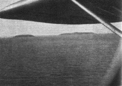
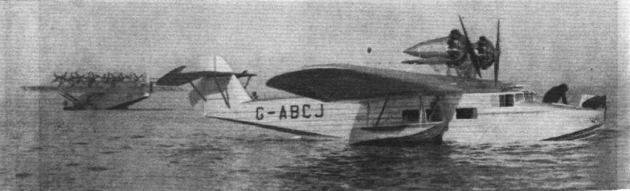
AS SEEN FROM THE "Do.X": The "snap" taken by Col. The Master of Sempill: two "Southamptons" moored off Calshot
Другие самолёты на фотографии: Supermarine Southampton / Solent - Великобритания - 1925
-

Aeroplane Monthly 1989-01 / ??? - Do X portfolio
Impressive view of the Do X in flight, taken from one of the engine supports.
-

Flight 1930-12 / Flight
AS SEEN FROM THE "Do.X": The "snap" taken by Col. The Master of Sempill: passing the Channel Islands.
-

Flight 1930-11 / Flight
Регистрационный номер: D-1929 [16] Another view of the "flying ship" at her moorings.
-

Flight 1930-11 / Flight
"Do.X" AND THE SARO "CLOUD." - This view showing the "Cloud," with the Prince on board, alighting alongside the "Do.X," illustrates the similarity of these two machines.
Другие самолёты на фотографии: Saunders-Roe Cloud / A.19 - Великобритания - 1930
-

Aeroplane Monthly 1997-06 / H.Amtmann - My Junkers years
Регистрационный номер: D-1929 [16] THREE BIG THINGS IN AVIATION: This photo - for which we have to thank our friends Shell-Mex Sc B.P.,Ltd. - taken recently over the Ausseralster, the larger of the two lakes in the centre of Hamburg, shows the Junkers G.38, the world's largest landplane, in flight; the Dornier Do. X, the world's largest flying-boat, moored on the left; and the new extensive Shell Haus on the lakeside on the right.
Другие самолёты на фотографии: Junkers G 38 - Германия - 1929
-

Flight 1931-02 / Flight
THE Do.X AT LISBON: A reader sends us the "snaps" of the Do. X beached for repairs.
-

Flight 1930-11 / Flight
SOME DETAILS OF THE DO.X: Some of the twelve 600 h.p. Curtiss "Conqueror" engines
-

Aeroplane Monthly 1987-10 / J.Stroud - Wings of Peace
Do X 2, the first for Italy, with Fiat engines.
-

Aviation Historian 32
Do X MM.182 Umberto Maddalena arrived in Italy in 1931 but never entered airline service, instead being allocated a military identity.
-

Aviation Historian 31 / M.Wickstead - Italy's forgotten airlines (1)
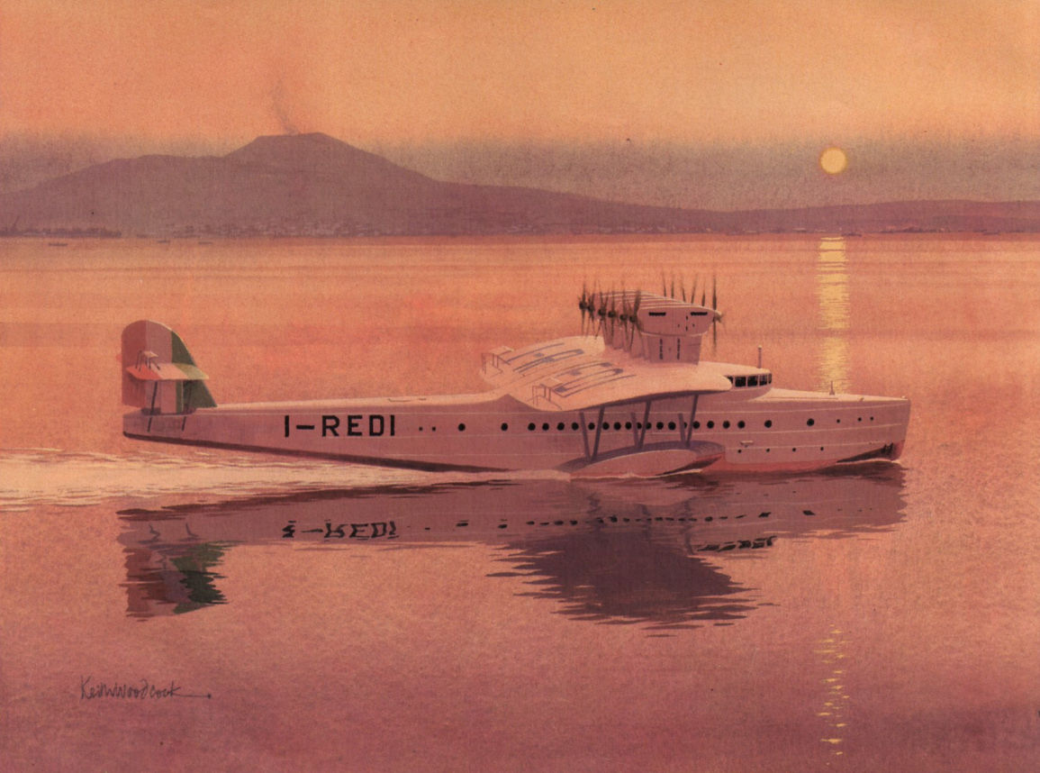
In 1931 SANA ordered two examples of Dornier’s massive Do X, powered by 12 Fiat A.22R 12-cylinder water-cooled engines. The Italian Do Xs were intended to be used on a prospective route from Trieste to Cadiz in Spain via Genoa, Marseille and Barcelona, but they never entered service with SANA and were ultimately scrapped.
-

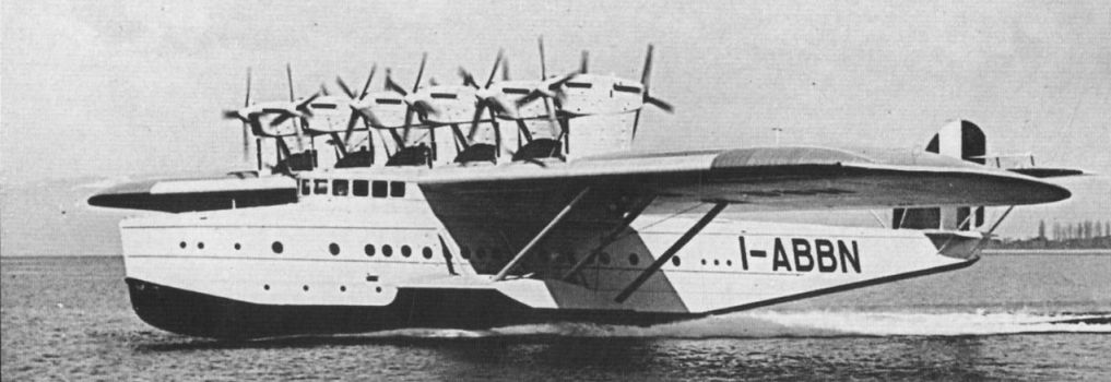
Aeroplane Monthly 1987-10 / J.Stroud - Wings of Peace
Регистрационный номер: I-ABBN Do X 3 Alessandro Guidoni.
-

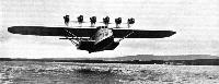
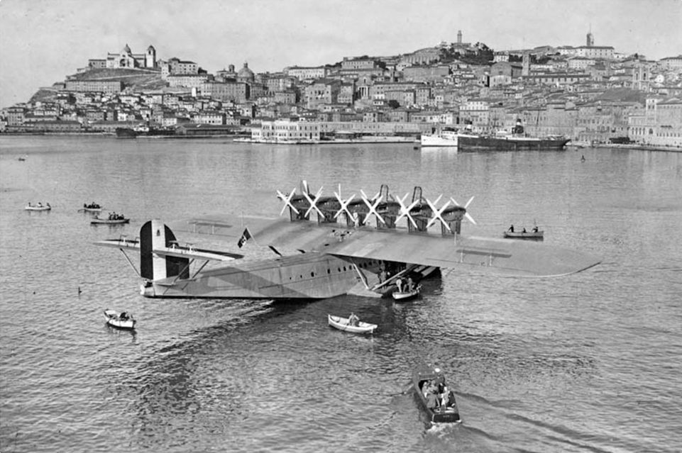
Aviation Historian 32
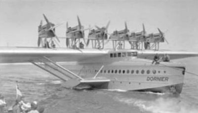
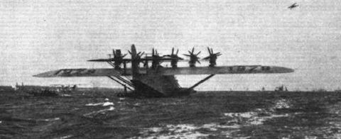
A dramatic image of one of Italy’s Dornier Do Xs soon after take-off, with water still streaming from the base of its water-rudder.
-

Aeroplane Monthly 1989-01 / ??? - Do X portfolio
This view, taken while taxying, clearly shows the layout of the Do X's complex tail structure.
-

Flight 1930-11 / Flight
Регистрационный номер: D-1929 [16] SOME DETAILS OF THE DO.X: A close-up of the tail.
-

Flight 1930-11 / Flight
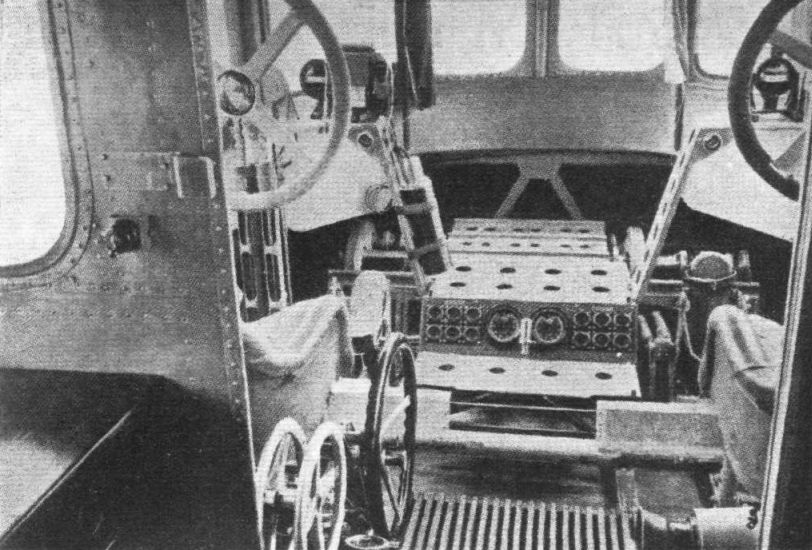
SOME DETAILS OF THE DO.X: The control cabin.
-
-

Aeroplane Monthly 1989-01 / ??? - Do X portfolio
The pilot's cabin.
-

Flight 1930-02 / Flight
The Do. X: View of the pilots' control cabin.
-

Flight 1930-02 / Flight
Отсек бортинженера был оснащен 12 отдельными комплектами оборудования для контроля и управления двигателями. Первоначально установленные на самолете моторы Bristol Jupiter из-за недостатка мощности заменили американскими двигателями Curtiss Conqueror.
The Engine Control Room is placed on the upper deck and communicates with the wing and, through it, the engine nacelles. -

Мировая Авиация 20
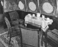
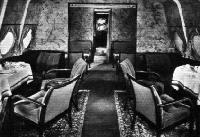
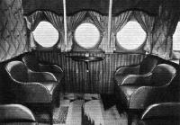
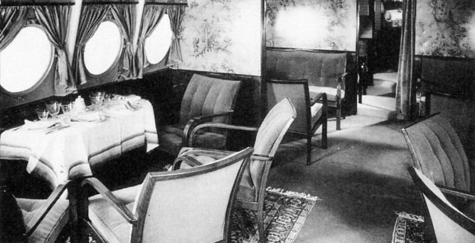
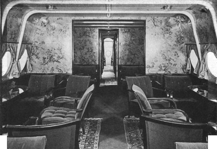
Благодаря роскошной отделке и комфорту пассажирского салона Do X, самолет часто сравнивали с воздушным отелем. Это сходство усиливала элегантная мебель и еда, не уступающая хорошему ресторану.
-
-

Aeroplane Monthly 1987-10 / J.Stroud - Wings of Peace
The photograph shows the excellent internal arrangements which have been made for the passengers' comfort, and also the tasteful interior decoration. The engines are accessible during flight, and by means of a small alley-way along the wing the mechanics are able to go from engine to engine, and should any engine stop and require attention this can readily be undertaken.
-
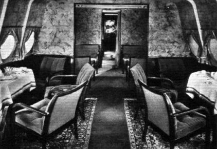
Flight 1932-07 / Flight
This view shows how comfortably furnished are the dining saloons.
-
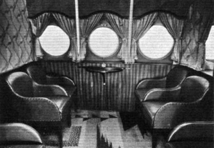
Flight 1932-07 / Flight
Few aircraft provide smoking facilities in as pleasant a manner as this.
-

Мировая Авиация 20
В ходе проектирования было построено много небольших моделей, а перед постройкой Do X сделали его полноразмерный деревянный макет, чтобы конструкторы могли обнаружить все возможные нестыковки.
-

Aeroplane Monthly 1989-01 / ??? - Do X portfolio
Full-scale mock-up of the Do X in one of the Friedrichshafen Zeppelin sheds.
-

Aeroplane Monthly 1987-10 / J.Stroud - Wings of Peace
Регистрационный номер: I-REDI KEITH WOODCOCK’S colour painting shows I-REDI, one of the two Do Xs ordered for the Italian service.
-

-

-

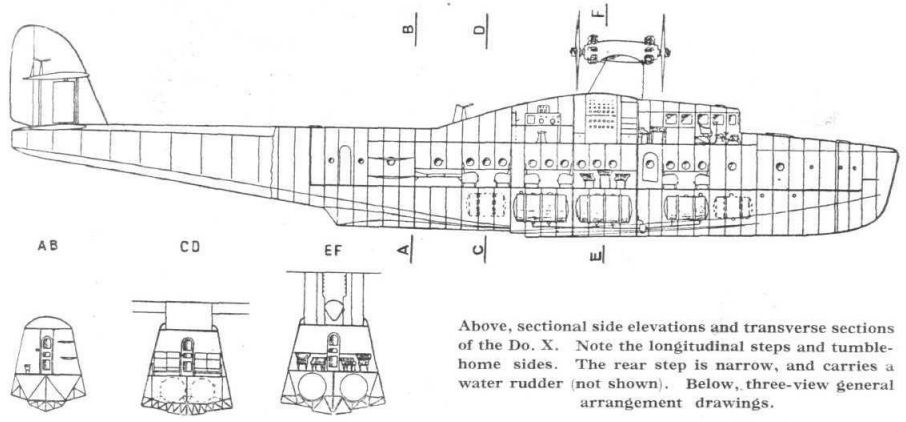
Flight 1930-02 / Flight
Sectional side elevations and transverse sections of the Do. X. Note the longitudinal steps and tumblehome sides. The rear step is narrow, and carries a water rudder (not shown).
-
Мировая Авиация 109
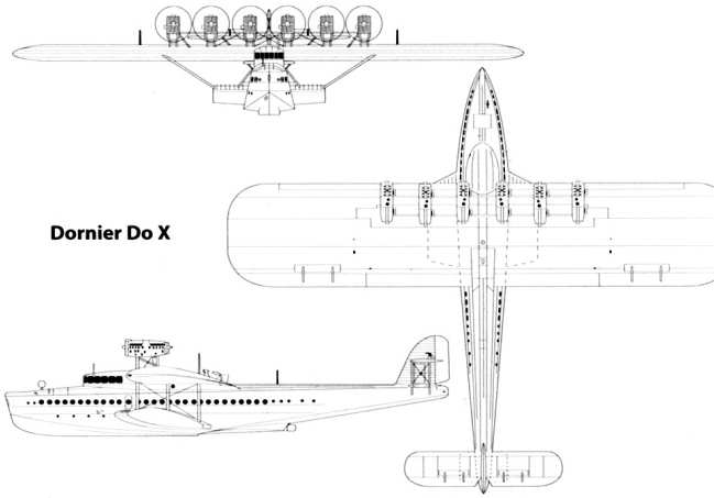
Dornier Do X
-

Flight 1930-02 / Flight
Dornier Do.X 12 Siemens-Jupiter 525 h.p. Engines


- Фотографии